Patent application title: METHOD FOR OPERATING AN ELECTRIC VEHICLE
Inventors:
Bernd Doerr (Wallduern, DE)
Roland Schleser (Loewenstein, DE)
Holger Niemann (Shangai, CN)
Markus Kretschmer (Murr, DE)
Oliver Kaefer (Murr, DE)
Daniel Damm (Ludwigsburg, DE)
Dirk Gollub (Karbach, DE)
Andreas Heyl (Ludwigsburg, DE)
Andreas Heyl (Ludwigsburg, DE)
IPC8 Class: AB60T8172FI
USPC Class:
701 22
Class name: Data processing: vehicles, navigation, and relative location vehicle control, guidance, operation, or indication electric vehicle
Publication date: 2011-07-14
Patent application number: 20110172866
Abstract:
A method for operating an electric vehicle, the electric vehicle having
an electric motor and a brake device, and the electric motor and the
brake device being capable of being influenced by a control device. When
the electric vehicle is at a standstill, when there is an error of the
control device, the brake device is actuated so that the electric vehicle
cannot move, or at least can move only to a very limited extent.Claims:
1. A method for operating an electric vehicle, the electric vehicle
having an electric motor and a brake device, the electric motor and the
brake device being capable of being influenced by a control device, the
method comprising: during a standstill of the electric vehicle, when
there is an error of the control device, actuating the brake device so
that the electric vehicle can move at most to a very limited extent.
2. The method according to claim 1, further comprising determining an error of the control device in that the electric vehicle executes a movement although the electric vehicle is supposed to remain at a standstill.
3. The method according to claim 1, further comprising determining an error of the control device in that the electric motor outputs a torque although the electric vehicle is supposed to remain at a standstill.
4. The method according to claim 1, wherein the brake device includes at least one of a disk brake, a wheel brake and a gear lock.
5. The method according to claim 1, wherein the method is executed independently of the control device.
6. A computer-readable medium containing a computer program which, when executed by a processor, performs a method for operating an electric vehicle, the electric vehicle having an electric motor and a brake device, the electric motor and the brake device being capable of being influenced by a control device, the method comprising: during a standstill of the electric vehicle, when there is an error of the control device, actuating the brake device so that the electric vehicle can move at most to a very limited extent.
7. A control device for operating an electric vehicle, the electric vehicle having an electric motor and a brake device, the control device comprising an arrangement for performing the following: during a standstill of the electric vehicle, when there is an error of the control device, actuating the brake device so that the electric vehicle can move at most to a very limited extent.
Description:
BACKGROUND INFORMATION
[0001] As is known, electric vehicles are driven by an electric motor that is for example supplied with power by a battery. The rotational speed of the electric motor, and thus the speed of the electric vehicle, is monitored by an electronic control device and is controlled and/or regulated in the desired manner. In particular, the electric motor is switched off when the electric vehicle is to be brought to a standstill or is to remain at a standstill.
[0002] If an error occurs in the control device during such a standstill of the electric vehicle, it is possible for the electric motor to briefly produce a torque that causes an undesired movement of the electric vehicle. In order to avoid accidents, in this case it is required that, even given an error in the control device, an electric vehicle at a standstill must not be permitted to execute a movement greater than 10 cm.
SUMMARY OF THE INVENTION
[0003] In the method according to the present invention, it is assumed that the electric vehicle is at a standstill. If, during this standstill, an error occurs in the control device, it is provided that a brake device is actuated so that the electric vehicle cannot move, or at least can move only to a very limited extent. In this way, it is ensured that even when there is an error of the control device the stationary electric vehicle will not make any movement greater than 10 cm.
[0004] It is particularly advantageous if a disk brake or a wheel brake or a gear lock or the like is provided as a brake device. This device should preferably be capable of being activated electrically. This makes it possible to use already-existing brake devices of the electric vehicle in order to realize the present invention.
[0005] In an advantageous realization, the method according to the present invention is carried out independent of the control device. In this way it is achieved that the method can still be carried out even if the control device is for example completely out of operation.
BRIEF DESCRIPTION OF THE DRAWINGS
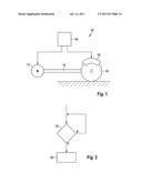
[0006] FIG. 1 shows a schematic switching diagram of an electric vehicle according to the present invention.
[0007] FIG. 2 shows a schematic flow diagram of an exemplary embodiment of a method according to the present invention for operating the electric vehicle shown in FIG. 1.
DETAILED DESCRIPTION
[0008] FIG. 1 shows a part of an electric vehicle 10, namely its electric motor 11, by which a wheel 13 of electric vehicle 10 can be driven via a drive shaft 12. Wheel 13 is for example provided with a brake device 14. In addition, a control device 16 is present that is capable of influencing electric motor 11 and brake device 14. In particular, control device 16 contains a microprocessor that is programmed in such a way that electric motor 11 produces a torque that acts on drive shaft 12 and that results in a desired speed of electric vehicle 10. In addition, control device 16 is fashioned in such a way that it actuates brake device 14 so that electric vehicle 10 can be braked thereby.
[0009] Alternatively, it is possible for control device 16 to be fashioned as a higher-order vehicle guidance computer, and for an additional control device to be connected between this higher-order control device 16 and electric motor 11, and/or between control device 16 and brake device 14. The intermediately connected control devices can then be oriented specifically to the devices that are to be controlled in each case, for example in the form of a special braking control device for controlling brake device 14.
[0010] If electric vehicle 10 is to be brought to a standstill or is to remain at a standstill, electric motor 11 is shut off by control device 16. This means that electric motor 11 is controlled by control device 16 in such a way that electric motor 11 no longer produces a torque at drive shaft 12. This has the consequence that wheel 13 is no longer driven, so that, as desired, the electric vehicle comes to a standstill and remains at a standstill.
[0011] This influencing of electric motor 11 by control device 16 is independent of any additional braking that may be present of electric vehicle 10 using any other brake devices.
[0012] It is possible that an error may occur in control device 16 that causes electric motor 11 to produce a torque that would then cause an undesired movement of the electric vehicle. In order to prevent such an undesired movement, the method explained in the following is provided.
[0013] In the method illustrated in FIG. 2, it is assumed that electric vehicle 10 is at a standstill. This means that, as mentioned, electric motor 11 is switched off. It is further assumed that brake device 14 has not been actuated by the driver, or has been actuated only to a slight extent by the driver, so that electric vehicle 10 is at an unbraked standstill.
[0014] In a step 21, it is continuously determined whether control device 16 is operating without error. This determination can be made using known measures. In particular, an error of control device 16 can be determined if electric vehicle 10 executes an undesired movement, or if electric motor 11 outputs a torque, although electric vehicle 10 is in both cases supposed to remain at a standstill.
[0015] If no error is present, then, as mentioned, step 21 is continuously repeated. If, on the other hand, an error is recognized, in a step 22 brake device 14 is actuated. Due to the continuous execution of step 21, and due to a processing speed of steps 21 and 22 that is as high as possible, it can be ensured that the actuation of the brake device takes place so quickly in terms of time that, despite the present torque of electric motor 11, electric vehicle 10 does not move, or moves only to a very limited extent.
[0016] Of course, brake device 14 can be any device of electric vehicle 10 that is suitable for holding electric vehicle 10 at a standstill. In addition, this device should be capable of being activated electrically to the greatest possible extent. For example, this device can be a disk brake coupled to wheel 13, or, as is shown as an example in FIG. 1, can be a wheel brake, or can be a gear lock of a gear that is connected in rotationally fixed fashion to wheel 13, or can be the simultaneous actuation of both clutches of a double-clutch transmission connected in rotationally fixed fashion to wheel 13, or the like.
[0017] If, contrary to the above-stated assumption, electric vehicle 10 is not at an unbraked standstill, so that electric vehicle 10 is braked in some way in the existing standstill and is thereby held stationary, to this extent a movement of electric vehicle 10 should then not be possible. In this case, the method explained above results in increased safety only in that a movement of electric vehicle 10 is not possible under any circumstances.
[0018] The method as recited in FIG. 2 can be executed by control device 16 or by a higher-order control device or by an intermediately connected control device. Alternatively, it is possible for the method to be executed by a device that is independent of control device 16 and that is able to actuate brake device 14. This device can for example be an additional microprocessor or a so-called ASIC. In this case, the method illustrated in FIG. 2 can also still be executed if for example the microprocessor of control device 16 is completely out of operation. It is also possible for a plurality of hardware and software levels to be realized in control device 16, for example a functional level and a monitoring level, and for the method illustrated in FIG. 2 to be present in the monitoring level. Thus, if an error is present in the functional level, the described method can continue to be executed by the monitoring level.
User Contributions:
Comment about this patent or add new information about this topic:
Images included with this patent application:
 |
| Similar patent applications: | |
| Date | Title |
|---|---|
| 2008-11-06 | Method of operating a plug-in hybrid electric vehicle |
| 2009-12-03 | Methods and systems for dynamically controlling hill rollback of an electric vehicle |
| 2008-10-16 | Method and device for controlling an electronic brake of a vehicle |
| 2009-05-07 | Optimal selection of blended braking capacity for a hybrid electric vehicle |
| 2010-02-25 | System for detecting interrupt conditions during an electric vehicle charging process |
| New patent applications in this class: | |
| Date | Title |
|---|---|
| 2022-05-05 | Vehicle motion management system and a motion support system for a vehicle |
| 2022-05-05 | Method for actively changing the frictional value of a hybrid disconnect clutch installed in a power train of a vehicle |
| 2022-05-05 | Device for prediction of vehicle state and storage medium |
| 2022-05-05 | Method for operating a motor vehicle and the corresponding motor vehicle |
| 2019-05-16 | Self-propelled monitoring device |
| New patent applications from these inventors: | |
| Date | Title |
|---|---|
| 2015-09-10 | Emergency operating mode for a piston engine in an airplane |
| 2015-08-06 | Method for monitoring drives |
| 2015-02-19 | Damage limitation for a motor vehicle in a dangerous situation |
| 2014-06-26 | Security architecture, battery and motor vehicle having a corresponding battery |
| 2014-06-05 | Warning system for monitoring a vehicle battery |
| Top Inventors for class "Data processing: vehicles, navigation, and relative location" | |
| Rank | Inventor's name |
|---|---|
| 1 | Anthony H. Heap |
| 2 | Ajith Kuttannair Kumar |
| 3 | Christopher P. Ricci |
| 4 | Roderick A. Hyde |
| 5 | Lowell L. Wood, Jr. |