Patent application title: BLADE FOR A TURBOMACHINE
Inventors:
Walter Enthammer (Anthering, AT)
IPC8 Class: AB64C27467FI
USPC Class:
416228
Class name: Fluid reaction surfaces (i.e., impellers) specific blade structure (e.g., shape, material, etc.) tined or irregular periphery
Publication date: 2011-07-14
Patent application number: 20110171037
Abstract:
A blade for a turbomachine, in particular for a rotor of a helicopter. A
main section is designed to create a flow in the surrounding medium and
extends from a hub section to a blade tip region. An end piece for
influencing eddy formation in the blade tip region. To achieve a
substantial noise reduction, the end piece is designed as a rounded flow
body comprising at least one groove originating in the transition region
between the body and the main section, substantially in the direction of
the blade axis and curving towards the trailing edge of the blade.Claims:
1. Blade for a turbomachine, in particular for a rotor of a helicopter,
comprising a main portion which is formed so as to create a flow in the
surrounding medium and which extends from a hub portion to a blade tip
region, an end piece for influencing eddy formation being provided in the
blade tip region, wherein the end piece is formed as a rounded flow body
comprising at least one groove, which starts substantially in the
direction of the blade axis, in a transition region into the main
portion, and curves towards the trailing edge of the blade.
2. Blade according to claim 1, wherein the groove ends substantially in the flow direction at the outline of the end piece.
3. Blade according to claim 1, wherein the groove joins a corresponding groove on the opposite profile side at the outline of the end piece.
4. Blade according to claim 1, wherein the groove is convex in form in the flow direction.
5. Blade according to claim 1, wherein the groove becomes increasingly deep starting from the transition region.
6. Blade according to claim 1, wherein the groove becomes increasingly wide starting from the transition region.
7. Blade according to claim 1, wherein at least three grooves are provided in succession.
8. Blade according to claim 1, wherein the end piece is formed asymmetrically about the plane of the rotor blade.
Description:
[0001] The invention relates to a blade for a turbomachine, in particular
for a rotor of a helicopter, comprising a main portion which is formed so
as to create a flow in the surrounding medium and which extends from a
hub portion to a blade tip region, an end piece for influencing eddy
formation being provided in the blade tip region.
[0002] Within the meaning of the invention, blades are understood to be components which are basically formed so as to influence flows in a medium, including in particular the blades of rotors such as the propellers of aeroplanes or the rotors of helicopters. However, the present invention also relates to turbomachines which are driven by the flow, for example blades in wind turbines or in turbines in general.
[0003] However, as well as these rotating components, the invention also relates to the wings of aeroplanes or the like.
[0004] It is known that eddies form in the relevant medium, when it flows around, in the region of the blade tip of a blade of this type, and not only influence the efficiency of the device but may also lead to noise problems. The issue of operating noise is particularly relevant in the field of helicopters in particular.
[0005] Various measures in the region of the blade tip have already been proposed for reducing the noise emission.
[0006] U.S. Pat. No. 5,785,282 A proposes a special backswept form of the blade tip with additional flow guiding surfaces. A similar solution is proposed in EP 0 493 303 B. U.S. Pat. No. 6,260,809 B discloses a further special form of the blade tip for influencing eddy formation. Reference should further be made to WO 2004/067956 A, which discloses a range of measures for increasing the efficiency of wind turbines.
[0007] All of the above solutions are relatively expensive and still only have an insufficient effect as regards reducing the noise emission. Further known solutions with similar drawbacks are disclosed in GB 557 581 A and U.S. Pat. No. 5,114,099.
[0008] It is an object of the present invention to develop a blade of the aforementioned type in such a way as to achieve a substantial reduction in eddy formation, and thus in noise emission, with the simplest possible construction. The efficiency of the turbomachine itself should not be reduced, but actually increased in so far as possible.
[0009] These objects are achieved according to the invention in that the end piece is formed as a rounded flow body comprising at least one groove, which starts substantially in the direction of the blade axis, in the transition region into the main portion, and curves towards the trailing edge of the blade.
[0010] Within the meaning of the present invention, the main portion is the part of the blade which by virtue of the particular contour thereof provides the majority of the flow effect. An end region defining the free end of the blade extends on one end of the main portion. The hub portion, which in rotors is located in the region of the axis of rotation, is arranged on the opposite end. In the case of a wing of a fixed-wing aircraft, the hub portion is considered to be the portion which forms the transition into the fuselage of the aeroplane.
[0011] The end piece is formed in a manner according to the invention as a rounded flow body, i.e. in a longitudinal section through the blade a smooth transition is provided from the upper side of the blade, the end piece curving constantly as far as an outline, and joining tangentially, with constant curvature, into the underside of the main portion from the outline. There is also a constant curvature from the front side to the rear side of the blade in the plane of the blade itself.
[0012] It is essential to the invention that at least one groove is provided in the end piece, and starts substantially in the axial direction of the blade and curves towards the trailing edge as it continues towards the periphery line. This groove has an influence on the flow in the region of the blade tip, and this influence has a favourable effect on the efficiency and noise emission.
[0013] It is particularly advantageous for the groove to end substantially in the flow direction at the outline of the end piece. In this way a particularly high efficiency can be achieved. The outline is the line which defines the maximum extent of the end piece in the plane of the blade in this region.
[0014] It is particularly advantageous for the groove to join a corresponding groove on the opposite profile side at the outline of the end piece. In this way, a continuous groove is formed, which is formed substantially V-shaped in form in a plan view and extends continuously from a transition region into the main portion on the blade upper side to a transition region into the main portion on the blade underside. This measure has been found to be particularly effective.
[0015] Further, it is particularly advantageous for the effect if the groove is convex in form in the flow direction. This means that the curvature is directed towards the trailing edge.
[0016] It is further particularly advantageous for the groove to become increasingly deep and wide starting from the transition region. A particularly large increase in the noise level can be achieved in this way.
[0017] A particularly advantageous variant configuration of the present invention provides that at least three grooves are provided in succession.
[0018] In the following, the present invention will be described in greater detail by way of the embodiments shown in the figures, in which:
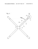
[0019] FIG. 1 is a schematic plan view of a rotor of a helicopter (not shown);
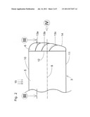
[0020] FIG. 2 is a detail II of the rotor of FIG. 1;
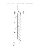
[0021] FIG. 3 is a section along the line III-III in FIG. 2;
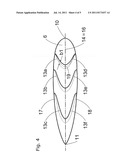
[0022] FIG. 4 is a view in the direction of the arrow IV in FIG. 2; and
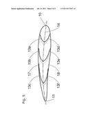
[0023] FIG. 5 shows an alternative variant configuration of the invention.
[0024] The rotor 2 of FIG. 1 has four blades 3. Each of the blades 3 has a hub portion 4, a main portion 5, and an end piece 6 in the blade tip region 7. The main portion 5 is elongate in form and extends substantially along the blade axis 8.
[0025] The direction of rotation of the rotor is shown by the arrow 9, and so the blade 3 has a leading edge 10 and a trailing edge 11.
[0026] FIG. 2 shows the blade tip region 7 on an enlarged scale. There is a transition region 12, drawn as a corresponding contour line, between the main portion 5 and the end piece 6.
[0027] On the upper side 17 (visible in FIG. 2) of the blade 3, the end piece 6 has three grooves 13a, 13b, 13c, which start substantially parallel to the blade axis 8 in the transition region 12 and extend with a constant curvature towards the outline 14. The grooves 13a, 13b, 13c are thus convex towards the leading edge 10. The flow direction of the surrounding medium is shown by the arrows 15 in FIG. 2.
[0028] It is clear from FIG. 3 that the width of the end piece 6 is approximately 80% of the thickness, the thickness being the greatest extent of the blade 3 in the transition region 12 transverse to the plane 16 of the rotor blade 3.
[0029] FIG. 4 is exaggerated to make it easier to understand the thickness dimension. It is clear that the end piece 6 is formed symmetrically about the plane 16 of the rotor blade 3. In the region of the outline 14, the grooves 13a, 13b, 13c on the upper side 17 therefore transition into analogous grooves 13d, 13e and 13f on the underside 18 of the end piece 6. By way of example, 19 denotes the centreline of the groove 13a, which is convex in form towards the leading edge 10 and transitions into the outline 14 substantially tangentially. It is further clear that the width b1 of the groove 13a becomes greater towards the outline 14. The depth (not shown) of the groove 13a also increases.
[0030] The variant configuration of FIG. 5 shows an application in which the blade 3 has a wing profile, rather than being formed symmetrically in the blade tip region 7.
[0031] These transition regions between the mutually associated grooves 13a, 13d; 13b, 13e; 13c, 13f are flow-optimised and rounded.
[0032] The present invention makes it possible to reduce the noise emissions of turbomachines considerably.
User Contributions:
Comment about this patent or add new information about this topic:
| People who visited this patent also read: | |
| Patent application number | Title |
|---|---|
| 20210295592 | Methods for Collecting and Processing Image Information to Produce Digital Assets |
| 20210295591 | PRIMITIVE FRAGMENT PROCESSING IN THE RASTERIZATION PHASE OF A GRAPHICS PROCESSING SYSTEM |
| 20210295590 | Systems and Methods for Soft Shadowing in 3-D Rendering Casting Multiple Rays from Ray Origins |
| 20210295589 | DENOISING TECHNIQUES SUITABLE FOR RECURRENT BLURS |
| 20210295588 | Decoder Unit for Texture Decompression |
Images included with this patent application:
 |  |
 |  |
 |
| Similar patent applications: | |
| Date | Title |
|---|---|
| 2009-08-13 | Blade with a cooling groove for a bladed wheel of a turbomachine |
| 2008-12-04 | Blade of a turbomachine |
| 2009-09-24 | Blade of a turbo machine |
| 2010-06-24 | One-piece bladed drum of an axial turbomachine compressor |
| 2010-08-26 | Blade retaining device for turbo machine propeller |
| New patent applications in this class: | |
| Date | Title |
|---|---|
| 2018-01-25 | Blade with corrugated outer surface(s) |
| 2016-06-23 | Rotor blade for a wind turbine, and wind turbine field |
| 2016-06-23 | Rotor blade with vortex generators |
| 2016-04-28 | Ceiling fan blade |
| 2016-02-04 | Rotary impeller for mixing and grinding materials |
| Top Inventors for class "Fluid reaction surfaces (i.e., impellers)" | |
| Rank | Inventor's name |
|---|---|
| 1 | Frank B. Stamps |
| 2 | Ching-Pang Lee |
| 3 | Gabriel L. Suciu |
| 4 | Stefan Herr |
| 5 | Tracy A. Propheter-Hinckley |