Patent application title: Multi-Faceted Structure for Bombs and Warheads Including Penetrating Warheads
Inventors:
James D. Ruhlman (Santa Rosa Beach, FL, US)
IPC8 Class: AF42B2500FI
USPC Class:
102382
Class name: Ammunition and explosives drop bombs
Publication date: 2011-07-14
Patent application number: 20110168048
Abstract:
A bomb and penetrating warhead ("PW") casings is disclosed that has three
or more exterior facets. The facets may be straight or spiraling. The
resulting bomb or PW casing that results is a stronger, tougher structure
that will increase the overall performance of the bomb or PW casing in
delivering the desired destructive power to a selected target. The bomb
and PW casings also have the advantage of being lighter in weight than a
conventional bomb structure but yet provide the desired destructive power
to the selected target.Claims:
1. A bomb casing, comprising: (A) an elongated main body section having
at least three exterior facets with the elongated main body section
further having (1) a proximal end, (2) a distal end, (3) a main body
central cavity extending from the proximal end to the distal end, and (4)
a wall thickness determined by the central cavity and the facets at an
exterior of the elongated main body section, with a cross-sectional wall
thickness of the elongated main body varying at least a location at a
center of a facets and a location where two facets meet; and (B) an ogive
shaped nose section that connects to the proximal end of the elongated
main body section with the nose section further having (1) a number of
exterior facets equal to the number of facets of the elongated main body
section, (2) an open nose distal end having substantially a same external
size and shape as the proximal end of the elongated main body section,
(3) a closed nose proximal end, and (4) a nose central cavity that
extends from the open nose distal end to the closed nose proximal end.
2. The bomb casing as recited in claim 1, wherein the proximal end of the nose section includes a threaded member receiving at least nose guidance kits.
3. The bomb casing as recited in claim 1, wherein the distal end of the elongated main body section is adapted for receiving at least tail guidance kits.
4. The bomb casing as recited in claim 1, wherein the distal end of the elongated main body section is adapted for receiving a rocket motor.
5. The bomb casing as recited in claim 1, wherein the elongated main body section is adapted for receiving at least guidance structures.
6. The bomb casing as recited in claim 1, wherein the cross-sectional wall thickness of the elongated main body section is substantially uniform at least at the center of the facets.
7. The bomb casing as recited in claim 1, wherein the wall thickness of the nose section includes being thicker at the closed nose proximal end.
8. A bomb casing, comprising: (A) an elongated main body section having at least three exterior facets spiraling around the elongated main body section, with the elongated main body section further having (1) a proximal end, (2) a distal end, (3) a main body central cavity extending from the proximal end to the distal end, and (4) a wall thickness determined by the central cavity and the facets at an exterior of the elongated main body section, with a cross-sectional wall thickness of the elongated main body varying at least a location at a center of a facets and a location where two facets meet; and (B) an ogive shaped nose section that connects to the proximal end of the elongated main body section with the nose section further having (1) a number of exterior spiraling facets equal to the number of spiraling facets of the elongated main body section, (2) an open nose distal end having substantially a same external size and shape as the proximal end of the elongated main body section, (3) a closed nose proximal end, and (4) a nose central cavity that extends from the open nose distal end to the closed nose proximal end.
9. The bomb casing as recited in claim 8, wherein the proximal end of the nose section includes a threaded member receiving at least nose guidance kits.
10. The bomb casing as recited in claim 8, wherein the distal end of the elongated main body section is adapted for receiving at least tail guidance kits.
11. The bomb casing as recited in claim 8, wherein the distal end of the elongated main body section is adapted for receiving a rocket motor.
12. The bomb casing as recited in claim 8, wherein the elongated main body section is adapted for receiving at least guidance structures.
13. The bomb casing as recited in claim 8, wherein the wall thickness of the nose section includes being thicker at the closed nose proximal end.
14. A bomb casing, comprising: (A) an elongated main body section having at least three exterior facets spiraling around the elongated main body section, with the elongated main body section further having (1) a proximal end, (2) a distal end, (3) a main body central cavity extending from the proximal end to the distal end, and (4) a wall thickness determined by the central cavity and the facets at an exterior of the elongated main body section, with a cross-sectional wall thickness of the elongated main body varying at least a location at a center of a facets and a location where two facets meet; and (B) an ogive shaped nose section that connects to the proximal end of the elongated main body section with the nose section further having (1) a number of facets equal to the number of exterior facets of the elongated main body section, (2) an open nose distal end having substantially a same external size and shape as the proximal end of the elongated main body section, (3) a closed nose proximal end, and (4) a nose central cavity that extends from the open nose distal end to the closed nose proximal end.
15. The bomb casing as recited in claim 14, wherein the proximal end of the nose section includes a threaded member receiving at least nose guidance kits.
16. The bomb casing as recited in claim 14, wherein the distal end of the elongated main body section is adapted for receiving at least tail guidance kits.
17. The bomb casing as recited in claim 14, wherein the distal end of the elongated main body section is adapted for receiving a rocket motor.
18. The bomb casing as recited in claim 14, wherein the elongated main body section is adapted for receiving at least guidance structures.
19. The bomb casing as recited in claim 14, wherein the wall thickness of the nose section includes being thicker at the closed nose proximal end.
Description:
CROSS REFERENCE TO RELATED APPLICATIONS
[0001] This application claims the priority under 35 U.S.C. §119(e) of U.S. Provisional Application No. 60/972,942, filed Sep. 17, 2007, which is incorporated herein by reference.
TECHNICAL FIELD
[0002] The present invention relates generally to the structure of bombs and warheads for use in delivering high explosives to selected targets. More specifically, the present invention relates to the structure of bombs and warheads for use in delivering high explosives to selected targets but including hardened and difficult to reach targets.
BACKGROUND OF THE INVENTION
[0003] Bombs can have a bomb casing of a conventional or penetrating warhead (PW) type. "Conventional" as it is used herein in describing a bomb casing means the shape and characteristics of the bomb casing as would be currently understood in the bomb industry.
[0004] Typically, bomb casings are filled with high explosive material and an end cap is used to seal the open end. Finished bombs using these bomb casings may be in 250, 500, 1000, and 2000 lb. classes or larger. The selection of the particular class of bomb will depend on the amount of high explosive that needs to be delivered to a selected target. Such bombs have been in the U.S. weapons inventory for a number of years.
[0005] Conventional bomb and PW casings each have a prescribed wall thickness. For any given bomb pound class, the interior cavity of the bomb casing will be tightly filled with high explosive material so that the finished bomb of a particular class will deliver predictable destructive power to a selected target. Generally, these conventional bomb and PW casings have a cylindrical main body section with an ogive or series of cones to form the nose section. Although the structure has been modified to use stronger and tougher materials, many times these structures do not survive the penetrating event sufficient to deliver the destructive power to the selected target.
[0006] Many conventional bomb or PW casings are guided to the desired target through the use of fins, wings, spinning action or other vehicles that provide an aerodynamic structure that can be guided and controlled to desired target. This is accomplished through the connection of structures at the aft-end and/or nose of the bomb or PW casing or to the body of the casing.
[0007] There is a desire for improved bomb and PW casings, which are capable of having guidance systems connected to the aft-end/or nose of the bomb body or to the body of the casing, which are lighter, stronger and provide novel features yet still deliver the desired destructive power to the selected target. These attachments are for air guidance to the initial point of contact.
SUMMARY OF THE INVENTION
[0008] The present invention is directed to bomb and penetrating warhead ("PW") casings that have three or more exterior facets that may be straight or spiraling that provides a lighter, stronger, tougher structure that will increase the overall performance of the bomb or PW casing in delivering the desired destructive power to a selected target. The novel bomb and PW casings of the present invention may be used with rocket motors to increase the velocity and penetrating performance of the bomb or penetrating warhead. Further, the bomb or PW casing may be fitted with guidance kits at the aft-end and/or nose or the body section to assist in providing an aerodynamic structure that can be guided and controlled to the desired initial impact point on its way to the target.
[0009] In a first embodiment of the present invention, the bomb or PW casing will have an elongated main body section and nose section. Each of these sections may have three or more facets. Normally, the number of exterior facets for the elongated main body section and nose section will be the same. The exterior cross-sectional size and shape of the multi-faceted elongated main body section will be substantially the same along its length. However, it is understood that the size and shape may vary to some degree for aerodynamic purposes and still be within the scope of the present invention.
[0010] The exterior facets at the nose section of the taper from the exterior cross-sectional size and shape of the elongated main body section in a matter to form an ogive or a cone-shaped nose section. The closed front end of the nose section has a threaded nose member disposed in it to which a nose guidance kit may be attached. The aft-end of the first embodiment of the bomb or PW casing of the present invention is sealed with an end cap and is configured to receive an aft-end guidance kit and/or rocket motor attachment. The body section may also have attachments that assist in the guidance and control of the bomb or PW on its way to the impact point.
[0011] The interior cavity of the first embodiment of the bomb or PW casing may have a cylindrical shape and extend through the elongated main body section and through to the closed front end of the nose section. The interior cylindrical casing may be filled with high explosive or other desired material. Given the exterior-faceted shape of the elongated main body and nose sections, and the interior cylindrical cavity, the bomb or PW casing will have a varied wall thickness at cross-sectional locations along its length.
[0012] A second embodiment of the bomb or PW casing of the present invention, like the first embodiment, has an elongated main body section and a nose section. Each of these sections may have three or more exterior facets. Normally, the elongated main body section and nose section will have the same number of exterior facets. In the second embodiment, the elongated main body section will have a multi-faceted structure with substantially the same exterior cross-sectional size and shape along its length. However, it is understood that the exterior cross-sectional size and shape of the elongated main body section may vary to some degree for aerodynamic purposes and still be within the scope of the present invention.
[0013] The exterior facets at the nose section of the second embodiment of the present invention taper from the exterior cross-sectional size and shape of the elongated main body section in a matter to form an ogive or a cone-shaped nose section. The closed front end of the nose section has a threaded nose member disposed in it to which a nose guidance kit may be attached. The aft-end of the second embodiment of the bomb or PW casing of the present invention is sealed with an end cap and is configured to receive an aft-end guidance kit and/or rocket motor attachment.
[0014] The cross-sectional shape of the interior cavity of the second embodiment of the bomb or PW casing may substantially conform to the exterior cross-sectional shape of the bomb or PW casing so that wall thickness for the bomb or PW casing will be substantially uniform along its length. The interior cavity of the second embodiment of the bomb or PW casing of the present invention extends through the elongated main body section and through to the closed end of the nose section. The interior cavity may be filled with high explosive or other desired material.
[0015] A third embodiment of the bomb or PW casing of the present invention also has an elongated main body section and a nose section. Each of these sections may have three or more exterior facets. Normally, the number of exterior facets for the elongated main body section and nose section are the same. According to third embodiment, the facets spiral around the exterior of the elongated main body and nose sections. The elongated main body section will have a multi-faceted structure with substantially the same exterior cross-sectional size and shape along its length except that the external cross-sectional size and shape at two different locations along its length will be displaced according to the spiraling of the facets. However, it is understood that the exterior cross-sectioned size and shape of the elongated main body section may vary to some degree for aerodynamic purposes and still be within the scope of the present invention.
[0016] The exterior facets at the nose section of the third embodiment, although spiraling, will taper from the exterior cross-sectional size and shape of the elongated main body section in a matter to form an ogive or a cone-shaped nose section. The closed front end of the nose section has a threaded nose member disposed in it to which a nose guidance kit may be attached. The aft-end of the third embodiment of the bomb or PW casing of the present invention is sealed with an end cap and is configured to receive an aft-end guidance kit and or rocket motor attachment.
[0017] The interior cavity of the third embodiment of the bomb or PW casing may have a cylindrical shape and extend through the elongated main body section and through to the closed front end of the nose section. The interior cylindrical cavity may be filled with high explosive or other desired material. Given the exterior faceted shape of the elongated main body and nose sections, and the interior cylindrical cavity, the bomb or PW casing will have a varied wall thickness at cross-sectioned locations along its length, namely slightly thicker at certain locations because of the spiraling facets at the exterior of these sections.
[0018] Like the first, second, and third embodiments, a fourth embodiment of the bomb or PW casing of the present invention has an elongated main body section and a nose section. Each of these sections may have three or more exterior facets. Normally, the number of exterior facets for the elongated main body section and nose section are the same. According to fourth embodiment, the facets spiral around the exterior of the elongated main body section but not the nose section. The elongated main body section will have a multi-faceted structure with substantially the same external cross-sectional size and shape along its length except that the exterior cross-sectional size and shape at two different locations along its length will be displaced according to the spiraling of the facets. However, it is understood that the exterior cross-sectional size and shape of the elongated main body section may vary to some degree for aerodynamic purposes and still be within the scope of the present invention.
[0019] The exterior facets at the nose section of the fourth embodiment are straight and do not spiral. These facets taper from the exterior cross-sectional size and shape of the elongated main body section in a matter to form an ogive or a cone-shaped nose section. The closed front end of the nose section has a threaded nose member disposed in it to which a nose guidance kit may be attached. The aft-end of the fourth embodiment of the bomb or PW casing of the present invention is sealed with an end cap and is configured to receive an aft-end guidance kit and or rocket motor attachment.
[0020] The interior cavity opening of the fourth embodiment of the bomb or PW casing may have a cylindrical shape and extend through the elongated main body section and through to the closed front end of the nose section. The interior cylindrical cavity may be filled with high explosive or other desired material. Given the exterior faceted shape of the elongated main body and nose sections, and the interior cylindrical cavity, the bomb or PW casing will have a varied wall thickness such that it will be slightly thicker in certain locations along the length of the elongated main body section because of the spiraling facets at the exterior of the main body section and the positions along the length of the nose section because of the facets at the exterior of the nose section.
[0021] The present invention will be described in greater detail in the remainder of the specification referring to the drawings.
BRIEF DESCRIPTION OF THE DRAWINGS
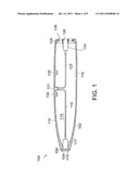
[0022] FIG. 1 shows a cross-section view of a conventional bomb casing that is filled with high explosives that may be fitted with a fuse system in the nose and tail sections.
[0023] FIG. 2 shows a cross-sectional view of a conventional penetrating warhead bomb casing that is filled with high explosives with a fuse system in tail section.
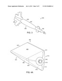
[0024] FIG. 3 shows a conventional warhead bomb casing with nose and tail guidance kits attached to it.
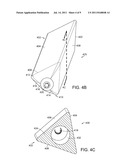
[0025] FIGS. 4A and 4B show front perspective views of a first embodiment of the bomb or PW casing of the present invention.
[0026] FIG. 4C shows a sectional perspective view of the first embodiment toward the nose section of the bomb or PW casing of the present invention shown along 4C-4C of FIG. 4B.
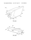
[0027] FIG. 5A shows front perspective view of a second embodiment of the bomb or PW casing of the present invention.
[0028] FIG. 5B shows side perspective view of the second embodiment of the bomb or PW casing of the present invention
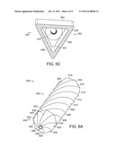
[0029] FIG. 5c shows a sectional perspective view of the second embodiment toward the nose section of the bomb or PW casing of the present invention shown along 5C-5C of FIG. 5B.
[0030] FIG. 6A shows front perspective view of a third embodiment of the bomb or PW casing of the present invention.
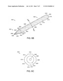
[0031] FIG. 6B shows side perspective view of the third embodiment of the bomb or PW casing of the present invention.
[0032] FIG. 6c shows a sectional view of the third embodiment toward the nose section of the bomb or PW casing of the present invention shown along 6C-6C of FIG. 6B.
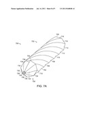
[0033] FIG. 7A shows front perspective view of a fourth embodiment of the bomb or PW casing of the present invention.
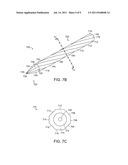
[0034] FIG. 7B shows side perspective view of the fourth embodiment of the bomb or PW casing of the present invention.
[0035] FIG. 7C shows a sectional view of the fourth embodiment toward the nose section of the bomb or PW casing of the present invention shown along 7C-7C of FIG. 7B.
DESCRIPTION OF THE PRESENT INVENTION
[0036] The present invention is directed to bomb and penetrating warhead ("PW") casings that have three or more exterior facets the may be straight or spiraling which results in a lighter, stronger, tougher structure that will increase the overall performance of the bomb or PW casing in delivering the desired destructive power to a selected target. The bomb and PW casings of the present invention may be used with rocket motors to increase the velocity and penetrating performance of the bomb or penetrating warhead, and such casings may be fitted with guidance kits at the aft-end and/or nose or on the main body section to assist in providing an aerodynamic structure that can be guided and controlled to the desired impact point on the way to the target.
[0037] Referring to FIG. 1, generally at 100, a longitudinal cross-sectional view of a conventional bomb casing is shown. The conventional bomb casing at 100, for example, may be a Mark 80 series bomb body. The bomb casing includes ogive-shaped, front section 102 and cylindrical-shaped, rear section 116. The bomb casing, preferably, is made of a low carbon steel 10XX, 41XX low alloy or for a specific application can be made of a high strength alloy steel, such as a 43XX alloy or higher strength material.
[0038] Ogive-shaped, front section 102 and cylindrical-shaped, rear section 116 may be formed separately or as a single unit and still be within the scope of the present invention.
[0039] The wall thickness of ogive-shaped, front section 102 progressively increases from rear edge 110 of this section to front end 104. Threaded bore 108 is disposed in front end 104 and extends through the front end wall thickness to central opening 114 in ogive-shaped, front section 102. Threaded bore 108 receives threaded bomb nose plug (not shown) in a screw-nut relationship. Nose fuse system 117 is shown that will receive the proximal end of the nose plug at 115.
[0040] Preferably, cylindrical-shaped, rear section 116 has a substantially uniform wall thickness, except at rear end 124. The wall thickness of the cylindrical-shaped, rear section is substantially the same as the wall thickness of ogive-shaped, front section 102 at rear edge 110. The cylindrical-shaped, rear section has central opening 122. The combination of central opening 114 in ogive-shaped, front section 102 and central opening 122 in cylindrical-shaped, rear section 116 form the interior cavity of bomb casing 102. The interior cavity a bomb casing 102 is filled with high explosives.
[0041] Cylindrical-shaped, rear section 116 has threaded bores 130 and 132. Each of the threaded bores receives the threaded base of a suspension lug (not shown). The suspension lugs are used for lifting the finished bombs and attaching them to aircraft bomb racks.
[0042] Cylindrical-shaped, rear section 116 also has charging receptacle 121. Charging tube 119 connects between charging receptacle 121 and nose fuse system 117. Charging tube 123 connects between charging receptacle 121 and tail fuse system 134.
[0043] End 124 of cylindrical-shaped, rear section 116 has threaded opening 136 that receives tail fuse system 134 and closure structure 136 that preferably is threaded into opening 126. A fin assembly (not shown) attaches to the aft-end closure structure 124. In the finished bomb, as stated, the interior cavity of the bomb casing is filled with high explosive material.
[0044] FIG. 2, generally at 200, shows a penetrating warhead ("PW") bomb casing that is currently available in a variety of sizes from 250 lbs. to over 5000 lbs. Similar to the casing shown in FIG. 1, the casing can have an ogive-shaped, front section 202 and cylindrical-shaped, rear section 210. The bomb casing, preferably, is made of a high strength alloy steel, such as a 43XX or higher strength material
[0045] The nose shape shown is ogive-shaped, front section 202 and cylindrical-shaped, rear section 210 may be formed separately or as a single unit and still be within the scope of the present invention.
[0046] The nose shape shown is ogive-shaped, front section 202 has a wall thickness that progressively increases from rear edge 206 of this section to forward end 204. The ogive-shaped, front section has central opening 208. Front end 204 of ogive-shaped, front section 202 has threaded nose portion 205 extending from it. Threaded nose portion 205 is for receiving a retaining ring of a guidance kit (not shown) in a threaded relationship.
[0047] Preferably, cylindrical-shaped, rear section 210 has a substantially uniform wall thickness, except at rear end 212. The wall thickness of the cylindrical-shaped, rear section is substantially the same as the wall thickness of ogive-shaped, front section 202 at rear edge 206. The cylindrical-shaped, rear section has central opening 214. The combination of central opening 208 and central opening 214 form the interior cavity of bomb casing 202. This interior cavity of the bomb casing is filled with high explosives.
[0048] Cylindrical-shaped, rear section 210 has charging receptacle 218. Charging tube 220 connects between charging receptacle 218 and tail fuse system 224. This charge tube is eliminated on some PW. End 212 of cylindrical-shaped, rear section 210 has opening 216 that receives tail fuse system 224 and aft-end closure structure 226. End 212 of cylindrical-shaped, rear section 210 has threaded opening 216 that receives tail fuse system 224 and closure structure 1026 that preferably is threaded into opening 1060. A fin assembly (not shown) attaches to aft-end closure structure 212. In the finished bomb, as stated, the interior cavity of the bomb casing is filled with high explosive material.
[0049] Cylindrical-shaped, rear section 210 may have an assembly attached to it for receiving the threaded bases of two or more suspension lugs (not shown). The suspension lugs, as stated, are used for lifting the finished bombs and attaching them to aircraft wing bomb mounts.
[0050] Referring to FIG. 3, generally at 300, a conventional PW casing is shown with guidance kits attached. In FIG. 3, PW casing 200 (FIG. 2) is shown with suspension lugs 302 and 304. PW casing 200 has nose guidance kit 306 attached to the threaded nose member 205 (FIG. 2) and tail guidance kit 308 attach to aft-end 212 (FIG. 2). Nose guidance kit 306 and tail guidance kit 308 are conventional and known in the bomb industry.
[0051] Referring to FIG. 4A, generally at 400, and FIG. 4B, generally at 425, front perspective views of the first embodiment of the bomb or PW casing of the present invention is shown. The first embodiment of the bomb or PW casing has elongated main body section 402 and nose section 410. Preferably, elongated main body section 402 and nose section 402 are made from a high strength alloy steel, such as 43XX or higher strength material. It is also understood that other materials may be used and still be at within the scope of the present invention.
[0052] The first embodiment of the bomb or PW casing of the present invention shows elongated main body section 402 with three exterior facets 404, 406, and 408. However, it is understood that elongated main body section 402 may have more than three exterior facets and still be within the scope of the present invention.
[0053] Exterior facets 404, 406, and 408 meet their respective adjacent facets in a rounded edge. However, the adjacent facets may meet in other than a rounded edge to provide specific aerodynamic properties for the bomb or PW casing and still be within the scope of the present invention.
[0054] Nose section 410 connects to front edge 409 of elongated main body section 402. Typically, nose section 410 will have, but is not required to have, the same number of exterior facets as elongated main body section 402. Accordingly, the nose section may have an equal number of exterior facets, or more or less exterior facets than the elongated main body section and still be within the scope of the present invention.
[0055] It is understood that the elongated main body section and nose section may be made as a single unit or separately and connected, and still be within the scope of the present invention.
[0056] As shown in FIGS. 4A and 4B, nose section 410 has three exterior facets 412, 414, and 416. Nose section facets 412, 414, and 416 meet their respective adjacent facets in a rounded edge. However, the adjacent facets may meet in other than a rounded edge to provide specific aerodynamic properties for the bomb or PW casing and still be within the scope of the present invention.
[0057] Exterior facets 412, 414, and 416 of nose section 410 taper down from the exterior cross-sectional size and shape of front edge 409 of elongated main body section 402 in a manner to form an ogive or a cone-shaped nose section. The closed front end of nose section 410 has threaded nose member 418 disposed in it that is adapted for receiving a nose guidance kit that is known in the bomb industry. FIGS. 4A and 4B show nose plug 420 disposed in threaded nose member 418.
[0058] Aft-end 422 of elongated main body section 402 of the bomb or PW casing of the present invention is sealed with an end cap and is configured to receive a tail guidance kit and/or rocket motor attachment that are known in the bomb industry. The tail guidance kit and/or rocket motor attachment are connected to aft-end 422 of elongated main body section 402 in a conventional manner.
[0059] Referring to FIG. 4C, generally at 430, a sectional view along 4C-4C of FIG. 4B is shown. FIG. 4C shows exterior facets 404, 406, and 408 of elongated main body section 402 and interior cylindrical cavity 432 of the bomb or PW casing. In this Figure, the rear end of threaded nose member 418 containing nose plug 420 is shown. Interior cylindrical cavity 432 is typically filled with high explosives or other desired materials, such as tungsten or other dense materials.
[0060] Again referring to FIG. 4C, shown generally at 430, wall thickness 434 of the bomb or PW casing varies according to the exterior cross-sectional size and shape of the elongated main body section 402 and nose section 410 as defined by the number of exterior facets of the casing and the cross-sectional size and shape of interior cylindrical cavity 432. The varying wall thickness of the casing may be used for providing the desired destructive power to a selective target.
[0061] It is understood that the diameter of interior cylindrical cavity 432 and the exterior cross-sectional size and shape of the elongated main body and nose sections may be changed, which will change the wall thickness, and it will still be within the scope of the present invention. It is also understood that the wall thickness at or near the closed front end of the nose section may be different, including thicker, and still be within the scope of the present invention.
[0062] Referring to FIG. 5A, generally at 500, and FIG. 5B, generally at 525, front and side perspective views of the second embodiment of the bomb or PW casing are shown, respectively. The second embodiment of the bomb or PW casing has elongated main body section 502 and nose section 510. Preferably, elongated main body section 502 and nose section 510 are made from a high strength alloy steel, such as 43XX or higher strength material. It is also understood that other materials may be used and still be at within the scope of the present invention.
[0063] The second embodiment of the bomb or PW casing of the present invention shows elongated main body section 502 with three exterior facets 504, 506, and 508. However, it is understood that elongated main body section 502 may have more than three exterior facets and still be within the scope of the present invention.
[0064] Exterior facets 504, 506, and 508 meet their respective adjacent facets in a rounded edge. However, the adjacent facets may meet in other than a rounded edge to provide specific aerodynamic properties for the bomb or PW casing and still be within the scope of the present invention.
[0065] Nose section 510 connects to front edge 509 of elongated main body section 502. Typically, nose section 510 will have, but is not required to have, the same number of exterior facets as elongated main body section 502. Accordingly, the nose section may have an equal number of exterior facets, or more or less exterior facets than the elongated main body section and still be within the scope of the present invention.
[0066] It is understood that the elongated main body section and nose section may be made as a single unit or separately and connected, and still be within the scope of the present invention.
[0067] As shown in FIGS. 5A and 5B, nose section 510 has three facets 512, 514, and 516. Nose section facets 512, 514, and 516 meet their respective adjacent facets in a rounded edge. However, the adjacent facets may meet in other than a rounded edge to provide specific aerodynamic properties for the bomb or PW casing and still be within the scope of the present invention.
[0068] Exterior facets 512, 514, and 516 of nose section 510 taper down from the exterior cross-sectional size and shape of front edge 509 of elongated main body section 502 in a matter to form an ogive or a cone-shaped nose section. The front closed end of nose section 510 has threaded nose member 518 that is adapted for receiving a nose guidance kit that is known in the bomb industry. FIGS. 5A and 5B show nose plug 520 disposed in threaded nose member 518.
[0069] Aft-end 522 of elongated main body section 502 of the bomb or PW casing of the present invention is sealed with an end cap and is configured to receive a tail guidance kit and/or rocket motor attachment that are known in the bomb industry. The tail guidance kit and/or rocket motor attachment are connected to aft-end 522 of elongated main body section 502 in a conventional manner.
[0070] Referring to FIG. 5c, generally at 530, a sectional view along 5C-5C of FIG. 5B is shown. FIG. 5c shows exterior facets 504, 506, and 508 of elongated main body section 502 and a portion of interior cavity 532 of the bomb or PW casing. In this Figure, the rear end of threaded nose member 518 containing nose plug 520 is shown. Interior cavity 532 is typically filled with high explosives or other desired materials, such as tungsten or other dense materials.
[0071] Again referring to FIG. 5c, shown generally at 530, wall thickness 534 of the bomb or PW casing is substantially uniform in the elongated and nose sections, except that the wall thickness may be thickened at or near the closed front end of the nose section and still be within the scope of the present invention. This uniform wall thickness may be used for providing the desired destructive power to a selective target.
[0072] It is understood that the cross-sectional size and shape of interior cylindrical cavity 532 and the exterior cross-section size and shape of the elongated main body and nose sections may be changed, which will change the wall thickness, and it will still be within the scope of the present invention.
[0073] Referring to FIG. 6A, generally at 600, and FIG. 6B, generally at 650, front and side perspective views of the third embodiment of the bomb or PW casing are shown, respectively. The third embodiment of the bomb or PW casing has elongated main body section 602 and nose section 630. Preferably, elongated main body section 602 and nose section 652 are made from a high strength alloy steel, such as 43XX or higher strength material. It is also understood that other materials may be used and still be at within the scope of the present invention.
[0074] The third embodiment of the bomb or PW casing of the present invention shows elongated main body section 602 with eight facets 604, 606, 608, 610, 612, 614, 616, and 618 that spiral around exterior of the elongated body section. However, it is understood that elongated main body section 602 may simply have more than three facets that spiral around the exterior of the elongated main body section and still be within the scope of the present invention.
[0075] Spiraling exterior facets 604, 606, 608, 610, 612, 614, 616, and 618 meet their respective adjacent facets in a rounded edge. However, the adjacent facets may meet in other than a rounded edge to provide specific aerodynamic properties for the bomb or PW casing and still be within the scope of the present invention.
[0076] Nose section 630 connects to front edge 603 of elongated main body section 602. Typically, nose section 630 will have, but is not required to have, the same number of facets as elongated main body section 602; and the exterior facets of the nose section of the third embodiment also will spiral.
[0077] It is understood that the elongated main body section and nose section may be made as a single unit or separately and connected, and still be within the scope of the present invention.
[0078] As shown in FIGS. 6A and 6B, nose section 630 has eight exterior facets 632, 634, 636, 638, 640, 642, 644, and 646. Spiraling nose section facets 632, 634, 636, 638, 640, 642, 644, and 646 meet their respective adjacent facets in a rounded edge. However, the adjacent spiraling facets may meet in other than a rounded edge to provide specific aerodynamic properties for the bomb or PW casing and still be within the scope of the present invention.
[0079] Spiraling exterior facets 632, 634, 636, 638, 640, 642, 644, and 646 of nose section 630 taper down from the exterior cross-sectional size and shape of front edge 603 of elongated main body section 602 in a manner to form an ogive or a cone-shaped nose section. The closed front end of nose section 630 has threaded nose member 648 disposed in it that is adapted for receiving a nose guidance kit that is known in the ordinance industry. FIGS. 6A and 6B show nose plug 649 disposed in threaded nose member 648.
[0080] Aft-end 605 of elongated main body section 602 of the bomb or PW casing of the present invention is sealed with an end cap and is configured to receive tail guidance kit and/or rocket motor attachment that are known in the bomb industry. The tail guidance kit and/or rocket motor attachment are connected to aft-end 605 of elongated main body section 602 in a conventional manner.
[0081] Referring to FIG. 6c, generally at 670, a sectional view along 6C-6C of FIG. 6B is shown. FIG. 6c shows exterior facets 604, 606, 608, 610, 612, 614, 616, and 618 of elongated main body section 602 and a portion of interior cylindrical cavity 672 of the bomb or PW casing. In the Figure, the rear end of threaded nose member 648 contains nose plug 649 as shown. Interior cylindrical cavity 672 is typically filled with high explosives or other desired materials, such tungsten or other dense materials.
[0082] Again referring to FIG. 6c, shown generally at 670, wall thickness 674 of the bomb or PW casing varies according to the exterior cross-sectional size and shape of the elongated main body section 602 and nose section 630 as defined by the number of exterior facets of the casing, and the cross-sectional size and shape of interior cylindrical cavity 672. The varying thickness of the casing may be used for providing the desired destructive power to a selective target.
[0083] It is understood that the size and shape of interior cylindrical cavity 672, and/or the exterior of the elongated and/or nose sections, may be changed, which will change wall thickness 674, and still be within the scope of the present invention. It is also understood that the wall thickness at or near the closed front end of the nose section may be different, including thickness, and still be within the scope of the present invention.
[0084] Referring to FIG. 7A, generally at 700, and FIG. 7B, generally at 750, front and side perspective views of the fourth embodiment of the bomb or PW casing are shown, respectively. The fourth embodiment of the bomb or PW casing has elongated main body section 702 and nose section 720. Preferably, elongated main body section 702 and nose section 720 are made from made of a high strength alloy steel, such as 43XX or higher strength material. It is also understood that other materials may be used and still be at within the scope of the present invention.
[0085] The fourth embodiment of the bomb or PW casing of the present invention shows elongated main body section 702 with eight facets 704, 706, 708, 710, 712, 714, 716, and 718 that spiral around the exterior of the elongated body section. However, it is understood that elongated main body section 702 may simply have more than three facets that spiral around the exterior of the elongated main body section and still be within the scope of the present invention.
[0086] Spiraling exterior facets 704, 706, 708, 710, 712, 714, 716, and 718 meet their respective adjacent facets in a rounded edge. However, the adjacent facets may meet in other than a rounded edge to provide specific aerodynamic properties for the bomb or PW casing and still be within the scope of the present invention.
[0087] Nose section 720 connects to front edge 703 of elongated main body section 702. Typically, nose section 720 will have, but is not required to have, the same number of exterior facets as elongated main body section 702, but in the fourth embodiment the exterior facets of the nose section do not spiral. Accordingly, the nose section may have an equal number of exterior facets, or more or less exterior facets than the elongated main body section and still be within the scope of the present invention.
[0088] It is understood that the elongated main body section and nose section may be made as a single unit or separately and connected, and still be within the scope of the present invention.
[0089] As shown in FIGS. 7A and 7B, nose section 720 has eight non-spiraling exterior facets 722, 724, 726, 728, 730, 732, 734, and 736. Non-spiraling exterior facets 722, 724, 726, 728, 730, 732, 734, and 736 meet their respective facets in a rounded edge. However, the adjacent spiraling facets may meet in other than a rounded edge to provide specific aerodynamic properties for the bomb or PW casing and still be within the scope of the present invention.
[0090] Non-spiraling exterior facets 722, 724, 726, 728, 730, 732, 734, and 736 of nose section 720 taper down from the exterior cross-sectional size and shape of front edge 703 of elongated main body section 702 in a manner to form an ogive or a cone-shaped nose section. The closed front end of nose section 720 has threaded nose member 738 dispensed in it that is adapted for receiving a nose guidance kit that is known in the bomb industry. FIGS. 7A and 7B show nose plug 739 disposed in threaded nose member 738.
[0091] Aft-end 705 of elongated main body section 702 of the bomb or PW casing of the present invention is sealed with an end cap and is configured to receive tail guidance kit and/or rocket motor attachment that are known in the bomb industry. The tail guidance kit and/or rocket motor attachment are connected to aft-end 705 of elongated main body section 702 in a conventional manner.
[0092] Referring to FIG. 6c, generally at 770, a sectional view along 7C-7C of FIG. 7B is shown. FIG. 7C shows exterior facets 704, 706, 708, 710, 712, 714, 716, and 718 of elongated main body section 702 and a portion of interior cylindrical cavity 772 of the bomb or PW casing. In this Figure, the rear end of threaded nose member 738 containing nose plug 739 is shown. Interior cylindrical cavity 772 is typically filled with high explosives or other desired materials, such as tungsten or other dense materials.
[0093] Again referring to FIG. 7C, shown generally at 770, wall thickness 774 of the bomb or PW casing varies according to the exterior cross-sectional size and shape of the elongated main body section 702 and nose section 720 as defined by the number of exterior facets of the casing, and the cross-sectional size and shape of interior cylindrical cavity 772. The varying thickness of the casing may be used for providing the desired destructive power to a selective target.
[0094] It is understood that the size and shape of interior cylindrical cavity 772, and/or the exterior of the elongated main body and nose sections, may be changed, which will change the wall thickness 774, and still be within the scope of the present invention. It is also understood that the wall thickness at or near the closed front end of the nose section may be different, including thicker, and still be within the scope of the present invention.
[0095] Is understood, that the spiraling facets that are shown in the structure of the third embodiment of the present invention at FIGS. 6A, 6B, and 6C, and fourth embodiment of the present invention at FIGS. 7A and 7B will cause the bomb or PW casing to spin even during the penetrating event to enhance the effectiveness of the bomb or PW using such casing in delivering the desired power to the selected target.
[0096] It is also understood the bomb or PW casings of the first, second, third, and fourth embodiments of the present invention may have suspension lugs for lifting and attachment to aircraft; charging receptacles; and nose and/or aft-end fuse systems and still be within the scope of the present invention.
[0097] The terms and expressions which are used herein are used as terms of expression and not of limitation. And, there is no intention, in the use of such terms and expressions, of excluding the equivalents of the features shown and described, or portions thereof, it being recognized that various modifications are possible in the scope of the invention.
User Contributions:
Comment about this patent or add new information about this topic:
| People who visited this patent also read: | |
| Patent application number | Title |
|---|---|
| 20130296925 | Tubular Patent Foramen Ovale (PFO) Closure Device with Catch System |
| 20130296924 | PATENT FORAMEN OVALE CLOSURE DEVICE |
| 20130296923 | Surgical Forceps |
| 20130296922 | Surgical Instrument With Stamped Double-Flag Jaws |
| 20130296921 | JUNCTIONAL TOURNIQUET |

