Patent application title: ENGINE INTAKE AIR FLOW CONTROL ASSEMBLY
Inventors:
Jian Jun Zhang (Rochester, MI, US)
Mark A. Mitchell (Dryden, MI, US)
Ko-Jen Wu (Troy, MI, US)
Ko-Jen Wu (Troy, MI, US)
Assignees:
GM GLOBAL TECHNOLOGY OPERATIONS, INC.
IPC8 Class: AF02M3510FI
USPC Class:
12318456
Class name: Intake manifold manifold tuning, balancing or pressure regulating means adjustable cross section passage
Publication date: 2011-07-07
Patent application number: 20110162611
Abstract:
An engine assembly may include a cylinder head, an intake manifold
assembly, first and second vanes, and an actuation mechanism. The first
and second vanes may be rotatably coupled to the intake manifold
assembly. The first vane may be located within an outlet of a first
intake passage and the second vane may be located within an outlet of a
second intake passage. The first and second vanes may be displaceable
from an open position to a closed position. The first vane may extend
along a wall defining the first intake passage when in the open position
and the second vane may extend along a wall defining the second intake
passage when in the open position. The actuation mechanism may be coupled
to the first and second vanes to rotate the first and second vanes
between the open and closed positions.Claims:
1. An intake air flow control assembly comprising: a plate adapted to be
located between an outlet of an intake manifold and a cylinder head, the
plate defining first and second intake passages providing communication
between the intake manifold outlet and first and second intake ports of
the cylinder head; a first vane rotatably coupled to the plate and
located within the first intake passage, the first vane displaceable from
an open position where the first vane extends along a first wall defining
the first intake passage to a closed position where the first vane
extends inwardly from the first wall to obstruct an air flow to the first
intake port; and a second vane rotatably coupled to the plate and located
within the second intake passage, the second vane displaceable from an
open position where the second vane extends along a second wall defining
the second intake passage to a closed position where the second vane
extends inwardly from the second wall to obstruct an air flow to the
second intake port.
2. The intake air flow control assembly of claim 1, further comprising a first pivot member rotatably coupled to the plate adjacent the first wall and a second pivot member rotatably coupled to the plate adjacent the second wall, the first vane fixed for rotation with the first pivot member and the second vane fixed for rotation with the second pivot member.
3. The intake air flow control assembly of claim 2, further comprising first, second and third arms, the first arm having a first end fixed for rotation with the first pivot member and a second end coupled to the third arm, the second arm having a first end fixed for rotation with the second pivot member and a second end coupled to the third arm.
4. The intake air flow control assembly of claim 3, further comprising an actuation mechanism coupled to the third arm, the third arm displaceable by the actuation mechanism to displace the first and second vanes between the opened and closed positions.
5. The intake air flow control assembly of claim 4, wherein the third arm is displaceable in a direction generally perpendicular to a rotational axis of the first pivot member.
6. The intake air flow control assembly of claim 2, wherein the first pivot member defines a first rotational axis spaced apart from and generally parallel to a rotational axis defined by the second pivot member.
7. The intake air flow control assembly of claim 1, wherein the plate defines a third intake passage providing communication between the intake manifold outlet and a third intake port of the cylinder head, the third intake passage being unobstructed when the first and second vanes are in the closed position.
8. An intake manifold assembly comprising: an intake manifold defining first and second intake passages providing air flow to first and second intake ports of a cylinder head; a first vane rotatably coupled to the intake manifold and located within an outlet of the first intake passage, the first vane displaceable from an open position where the first vane extends along a first wall defining the first intake passage to a closed position where the first vane extends inwardly from the first wall to obstruct an air flow to the first intake port; and a second vane rotatably coupled to the intake manifold and located within the second intake passage, the second vane displaceable from an open position where the second vane extends along a second wall defining the second intake passage to a closed position where the second vane extends inwardly from the second wall to obstruct an air flow to the second intake port.
9. The intake manifold assembly of claim 8, further comprising a first pivot member rotatably coupled to the intake manifold adjacent the first wall and a second pivot member rotatably coupled to the intake manifold adjacent the second wall, the first vane fixed for rotation with the first pivot member and the second vane fixed for rotation with the second pivot member.
10. The intake manifold assembly of claim 9, further comprising first, second and third arms, the first arm having a first end fixed for rotation with the first pivot member and a second end coupled to the third arm, the second arm having a first end fixed for rotation with the second pivot member and a second end coupled to the third arm.
11. The intake manifold assembly of claim 10, further comprising an actuation mechanism coupled to the third arm, the third arm displaceable by the actuation mechanism to displace the first and second vanes between the opened and closed positions.
12. The intake manifold assembly of claim 11, wherein the third arm is displaceable in a direction generally perpendicular to a rotational axis of the first pivot member.
13. The intake manifold assembly of claim 9, wherein the first pivot member defines a first rotational axis spaced apart from and generally parallel to a rotational axis defined by the second pivot member.
14. The intake manifold assembly of claim 8, wherein the intake manifold defines a third intake passage providing air flow to a third intake port of the cylinder head, the third intake passage being unobstructed when the first and second vanes are in the closed position.
15. An engine assembly comprising: a cylinder head defining first and second intake ports; an intake manifold assembly coupled to the cylinder head and defining a first intake passage in communication with the first intake port and a second intake passage in communication with the second intake port; a first vane rotatably coupled to the intake manifold assembly and located within an outlet of the first intake passage, the first vane displaceable from an open position where the first vane extends along a first wall defining the first intake passage to a closed position where the first vane extends inwardly from the first wall to obstruct an air flow to the first intake port; a second vane rotatably coupled to the intake manifold assembly and located within the second intake passage, the second vane displaceable from an open position where the second vane extends along a second wall defining the second intake passage to a closed position where the second vane extends inwardly from the second wall to obstruct an air flow to the second intake port; and an actuation mechanism coupled to the first and second vanes to rotate the first and second vanes between the opened and closed positions.
16. The engine assembly of claim 15, wherein the intake manifold assembly includes an intake manifold and a plate coupled to an outlet of the intake manifold and located between the intake manifold and the cylinder head, the plate defining the first and second intake passages.
17. The engine assembly of claim 15, further comprising a first pivot member rotatably coupled to the intake manifold assembly adjacent the first wall and a second pivot member rotatably coupled to the intake manifold adjacent the second wall, the first vane fixed for rotation with the first pivot member and the second vane fixed for rotation with the second pivot member.
18. The engine assembly of claim 17, further comprising first, second and third arms, the first arm having a first end fixed for rotation with the first pivot member and a second end coupled to the third arm, the second arm having a first end fixed for rotation with the second pivot member and a second end coupled to the third arm, the third arm coupled to the actuation mechanism.
19. The engine assembly of claim 17, wherein the first pivot member defines a first rotational axis spaced apart from and generally parallel to a rotational axis defined by the second pivot member.
20. The engine assembly of claim 15, wherein the intake manifold assembly defines a third intake passage providing air flow to a third intake port of the cylinder head, the third intake passage being unobstructed when the first and second vanes are in the closed position.
Description:
FIELD
[0001] The present disclosure relates to engine assemblies, and more specifically to intake air flow control in engines.
BACKGROUND
[0002] This section provides background information related to the present disclosure which is not necessarily prior art.
[0003] Internal combustion engines may combust a mixture of air and fuel in cylinders and thereby produce drive torque. Air and fuel flow into and out of the cylinders may be controlled by a valvetrain. Controlling air flow into the cylinders to generate swirl or tumble flow may enhance combustion at some operating conditions. Swirl and/or tumble flow may be generated by providing an obstruction in the intake air flow path. However, combustion at other operating conditions may benefit from an unobstructed intake air flow path.
SUMMARY
[0004] An intake air flow control assembly may include a plate, a first vane and a second vane. The plate may be adapted to be located between an outlet of an intake manifold and a cylinder head. The plate may define first and second intake passages providing communication between the intake manifold outlet and first and second intake ports of the cylinder head. The first vane may be rotatably coupled to the plate and located within the first intake passage. The first vane may be displaceable from an open position where the first vane extends along a first wall defining the first intake passage to a closed position where the first vane extends inwardly from the first wall to obstruct an air flow to the first intake port. The second vane may be rotatably coupled to the plate and located within the second intake passage. The second vane may be displaceable from an open position where the second vane extends along a second wall defining the second intake passage to a closed position where the second vane extends inwardly from the second wall to obstruct an air flow to the second intake port.
[0005] An intake manifold assembly may include an intake manifold, a first vane and a second vane. The intake manifold may define first and second intake passages providing air flow to first and second intake ports of a cylinder head. The first vane may be rotatably coupled to the intake manifold and located within an outlet of the first intake passage. The first vane may be displaceable from an open position where the first vane extends along a first wall defining the first intake passage to a closed position where the first vane extends inwardly from the first wall to obstruct an air flow to the first intake port. The second vane may be rotatably coupled to the intake manifold and located within the second intake passage. The second vane may be displaceable from an open position where the second vane extends along a second wall defining the second intake passage to a closed position where the second vane extends inwardly from the second wall to obstruct an air flow to the second intake port.
[0006] An engine assembly may include a cylinder head, an intake manifold assembly, first and second vanes, and an actuation mechanism. The cylinder head may define first and second intake ports. The intake manifold assembly may be coupled to the cylinder head and may define a first intake passage in communication with the first intake port and a second intake passage in communication with the second intake port. The first vane may be rotatably coupled to the intake manifold assembly and located within an outlet of the first intake passage. The first vane may be displaceable from an open position where the first vane extends along a first wall defining the first intake passage to a closed position where the first vane extends inwardly from the first wall to obstruct an air flow to the first intake port. The second vane may be rotatably coupled to the intake manifold assembly and located within the second intake passage. The second vane may be displaceable from an open position where the second vane extends along a second wall defining the second intake passage to a closed position where the second vane extends inwardly from the second wall to obstruct an air flow to the second intake port. The actuation mechanism may be coupled to the first and second vanes to rotate the first and second vanes between the open and closed positions.
[0007] Further areas of applicability will become apparent from the description provided herein. The description and specific examples in this summary are intended for purposes of illustration only and are not intended to limit the scope of the present disclosure.
BRIEF DESCRIPTION OF THE DRAWINGS
[0008] The drawings described herein are for illustrative purposes only and are not intended to limit the scope of the present disclosure in any way.
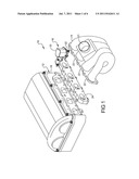
[0009] FIG. 1 is a perspective exploded view of a portion of an engine assembly according to the present disclosure;
[0010] FIG. 2 is a perspective view of the intake air flow control assembly shown in FIG. 1;
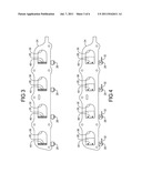
[0011] FIG. 3 is a plan view of the intake air flow control assembly of FIG. 2 in a first position;
[0012] FIG. 4 is a plan view of the intake air flow control assembly of FIG. 2 in a second position;
[0013] FIG. 5 is a perspective exploded view of a portion of an alternate engine assembly according to the present disclosure;
[0014] FIG. 6 is a perspective exploded view of a portion of an alternate engine assembly according to the present disclosure;
[0015] FIG. 7 is a plan view of the intake air flow control assembly of FIG. 6 in a first position; and
[0016] FIG. 8 is a plan view of the intake air flow control assembly of FIG. 6 in a second position.
[0017] Corresponding reference numerals indicate corresponding parts throughout the several views of the drawings.
DETAILED DESCRIPTION
[0018] Examples of the present disclosure will now be described more fully with reference to the accompanying drawings. The following description is merely exemplary in nature and is not intended to limit the present disclosure, application, or uses.
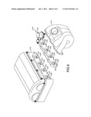
[0019] With reference to FIG. 1, an engine assembly 10 may include an engine structure 12, an intake manifold 14 and an intake air flow control assembly 16. The engine structure 12 may include a cylinder head 18 defining intake ports 20. The intake manifold 14 may be coupled to the cylinder head 18 and may include an inlet 21 and outlets 22 to provide air flow to the intake ports 20. The intake air flow control assembly 16 may be coupled to the cylinder head 18 and located between the outlets 22 of the intake manifold 14 and the intake ports 20.
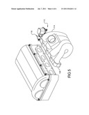
[0020] With additional reference to FIGS. 2-4, the intake air flow control assembly 16 may include a plate 24, vanes 26, pivot members 28, an actuation mechanism 30, pivot arms 32, an actuation arm 34 and an intermediate arm 36. The plate 24 may define intake passages 38. The vanes 26 may be located within the intake passages 38 and rotatably coupled to the plate 24 by the pivot members 28. The pivot members 28 may be located adjacent walls 40 defining the intake passages 38.
[0021] The pivot members 28 may define rotational axes spaced apart from and parallel to one another. A pivot arm 32 may be fixed for rotation with each of the pivot members 28 at a first end of the pivot arm 32. The pivot arm 32 may extend radially from the pivot member 28 and perpendicular relative to the rotational axis of the pivot member 28. Second ends of the pivot arms 32 may be rotatably coupled to the intermediate arm 36. The actuation arm 34 may be rotationally driven by the actuation mechanism 30 and engaged with the intermediate arm 36. By way of non-limiting example, the actuation mechanism 30 may include an electric motor.
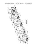
[0022] During operation, the vanes 26 may be displaced from an open position (FIG. 3) to a closed position (FIG. 4) by the actuation mechanism 30. Specifically, the actuation mechanism 30 may rotate the actuation arm 34 resulting in longitudinal displacement of the intermediate arm 36. As the intermediate arm 36 is displaced, the pivot arms 32 are rotated. Rotation of the pivot arms 32 causes the vanes 26 to rotate due to the engagement with the pivot members 28.
[0023] As seen in FIG. 3, the intake passages 38 may be generally unobstructed when the vanes 26 are in the open position. The location of the pivot members 28 may reduce a flow restriction in the intake passages 38 by locating the vanes 26 directly adjacent and parallel to the walls 40 when in the opened position. The vanes 26 may extend radially inward from the walls 40 when in the closed position seen in FIG. 4 to restrict air flow to the intake ports 20. The restriction provided when the vanes 26 are in the closed position may induce swirl or tumble flow (depending on the vane arrangement) within engine combustion chambers (not shown).
[0024] In another non-limiting example, seen in FIG. 5, the intake manifold assembly 113 may include the intake manifold 114 and the intake air flow control assembly 116. Specifically, the intake manifold 114 may include a plate region 128 integrally formed therewith as a monolithic member. The remainder of the intake air flow control assembly 116 may be generally similar to the intake air flow control assembly 16 described above and therefore will not be described in detail with the understanding that the description above applies equally.
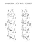
[0025] In yet another non-limiting example, seen in FIGS. 6-8, the intake air flow control assembly 216 may include first and second sets of intake passages 238, 239. The vanes 226 and pivot members 228 may be located in the first intake passages 238, leaving the second intake passages 239 unobstructed. The actuation mechanism 230 may be similar to the actuation mechanism 30 described above and therefore will not be described in detail with the understanding that the description above applies equally.
[0026] As seen in FIG. 6, the cylinder head 218 may define separate first and second intake ports 220, 221 for each combustion chamber (not shown) instead of a common inlet that branches into two intake ports for each combustion chamber as shown in FIG. 1. In the arrangement of FIGS. 6-8, the first intake ports 220 may be generally unobstructed when the vanes 226 are in the open position seen in FIG. 7. The vanes 226 may extend radially inward from the walls 240 when in the closed position seen in FIG. 8 to restrict air flow to the first intake ports 220. By way of non-limiting example, the first intake ports 220 may be completely closed by the vanes 226 when the vanes 226 are in the closed position, preventing air flow from the intake manifold 214 to the first intake ports 220.
[0027] Additionally, it is understood that the arrangement seen in FIGS. 6-8 may be incorporated in a system where the plate 224 and intake manifold 214 are formed as an integral member, such as the arrangement shown in FIG. 5.
User Contributions:
Comment about this patent or add new information about this topic:
| People who visited this patent also read: | |
| Patent application number | Title |
|---|---|
| 20110162715 | SYSTEM AND METHOD FOR REMOVING COATING FROM AN EDGE OF A SUBSTRATE |
| 20110162690 | TRANSPORTABLE SOLAR PANEL AND SUPPORT SYSTEM |
| 20110162689 | Solar Cell Module, Arrangement Structure of the Same, and Method for Arranging the Same |
| 20110162673 | MAKEUP METHOD AND A DEVICE FOR IMPLEMENTING SUCH A METHOD |
| 20110162671 | BLEACHING AGENT COMPRISING 2-ACYLPYRIDINIUM DERIVATIVES |
Images included with this patent application:
 |  |
 |  |
 |  |
| New patent applications in this class: | |
| Date | Title |
|---|---|
| 2015-02-12 | Systems and methods for multiple aspirators for a constant pump rate |
| 2014-12-04 | Mount structure of intake air flow control valve device |
| 2014-08-28 | Air intake system for internal combustion engine |
| 2014-05-22 | Intake pipe structure for internal combustion engine |
| 2013-08-29 | Variable intake device of engine |
| New patent applications from these inventors: | |
| Date | Title |
|---|---|
| 2016-04-14 | Cooled two-stage turbocharging system |
| 2016-04-07 | Control of internal combustion engine with two-stage turbocharging |
| 2015-08-27 | Two-stage turbocharger system for internal combustion engines featuring cylinder deactivation |
| 2015-03-12 | Compressor cover with integrated egr valve |
| 2015-02-05 | Turbocharging system |
| Top Inventors for class "Internal-combustion engines" | |
| Rank | Inventor's name |
|---|---|
| 1 | Ross Dykstra Pursifull |
| 2 | Gopichandra Surnilla |
| 3 | Joseph Norman Ulrey |
| 4 | Thomas G. Leone |
| 5 | Chris Paul Glugla |