Patent application title: Method and System For Tool Wear Indicator
Inventors:
Eryk Wangsness (Mankato, MN, US)
IPC8 Class: AE01H506FI
USPC Class:
37266
Class name: Excavating snow or ice removing or grooming by portable device scraper blade
Publication date: 2011-07-07
Patent application number: 20110162241
Abstract:
A wear indicator on a tool is provided that can be used to determine if
the blade or edge of the tool is worn past a predetermined point. It
provides for the easy identification of the condition of replacement wear
surfaces. The wear indicator or marking may be implemented in many ways
that will not interfere or impede in the integrity of the blade or tool.
Some examples include laser etching of the mark, a line pressed into the
surface of the blade, dimples along a line, a scribe mark, paint, a
material located inside of the product that becomes visible when the part
to be replaced, or any other suitable way to easily and visually
determine the condition of the blade.Claims:
1. A snow plow, comprising: a replaceable blade attached to the snow
plow: and a wear indicator on the replaceable blade indicating a level of
wear on the blade.
2. The snow plow of claim 1, wherein the wear indicator comprises a laser etching.
3. The snow plow of claim 1, wherein the wear indicator comprises is line pressed into a surface of the replaceable blade.
4. The snow plow of claim 1, wherein the wear indicator comprises dimples along a line on the replaceable blade.
5. The snow plow of claim 1, wherein the wear indicator comprises paint.
6. The snow plow of claim 1, wherein the wear indicator comprises a material that becomes visible upon the level of wear on the blade,
7. A method of using a replaceable blade on a snow plow, comprising: applying a wear indicator to a replaceable blade; attaching the replaceable blade to the snow plow; determining whether the wear indicator is visible on the replaceable blade; and replacing the replaceable blade based on the determination of whether the wear indicator is visible on the replaceable blade.
Description:
RELATED APPLICATION
[0001] This application claims benefit to U.S. Provisional Patent Application Ser. No. 61/292,880 filed Jan. 7, 2010, entitled "Method and System for Tool Wear Indicator" which is incorporated by reference herein.
FIELD OF THE INVENTION
[0002] This generally relates to replaceable blades, and in particular, wear indicators on replaceable blades.
BACKGROUND
[0003] Replacement blades or tips are common on tools in the construction, snow removal, mining, dredging, forestry and agriculture industries. Examples of replacement blades include snow plow equipment, buckets for skid steers, blades for road grading equipment, chisel plow or bottom plows, blades used on combine heads for corn or any other harvesting of agriculture products, excavator edges and lip segments, cutting edges for mining, dredging cutterhead teeth and gyrator crusher wear parts. However, many other example blades exist.
[0004] Conventionally, the operator or equipment maintenance personnel determine the condition of wear surfaces by measurement, guess and/or personal experience. However, advanced warning of blade wear would avoid damage to equipment, save money and help reduce the risk of injury to users.
[0005] U.S. Pat. No. 4,888,009 (`009 patent) involves a wear indicator for a guide for tools to follow in the removal of material. The `009 is patent is used exclusively for a templates or guides to other equipment used in manufacturing. These guides or templates are used by other equipment to aid in the removal of material to a predetermined shape. The `009 involves light-weight composite materials better-suited for guides and templates and not capable of performing the actual work of cutting or removing materials. The `009 patent does not involve actual cutting or wear surfaces of tools, such as, for example, the replaceable blades on snow removal equipment. It does not disclose the involvement of a blade that is the tool doing the physical work by removing materials. It also does not disclose the application to non-composite materials, such as steel or other materials suited for the cutting or removal of materials.
[0006] Accordingly, there is a desire for a method and system to avoid these and other related problems.
DETAILED DESCRIPTION
[0007] Methods and systems in accordance with the present invention provide a wear indicator on a tool that can be used to determine if the blade or edge of the tool is worn past a predetermined point. They provide for the easy identification of the condition of replacement wear surfaces. The wear indicator or marking may be implemented in many ways that will not interfere or impede in the integrity of the blade in question. Some examples include laser etching of the mark, a line pressed into the surface of the blade, dimples along a line, a scribe mark, paint, a material located inside of the product that becomes visible when the part to be replaced, or any other suitable way to easily and visually determine the condition of the blade.
[0008] If the mark is not readily visible, this indicates a need for replacement of the tool or blade so that costly damage does not occur to the main device. In the instance of embedded and hidden material for the mark, if it becomes visible, this also indicates the need for replacement to prevent costly down time and damaged equipment. For example, the blades on a snow plow or skid steer need to be changed periodically so for the optimum use of the tool and to prevent damage to the main tool such as the body of snow plow, bucket on a skid or farm implement. The wear indicator can easily identify for a user when the blade needs replacing or maintenance.
[0009] Method and systems consistent with the present invention can be used on anything that has a wear surface that needs to be maintained and/or replaced. It may be a direct indicator of the length of life left in the tool. These methods and systems may operate on the actual cutting or wear surfaces, such as the replaceable blades on snow removal equipment. The blade is the tool doing physical work by removing materials. The actual working surface may be made up of steel or other materials suited for the slicing, removal or changing of materials.
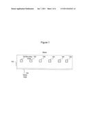
[0010] FIG. 1 depicts a blade without a wear indicator. As shown on the Figure, blade 102 has mounting holes 104 used to mount the blade on another piece of equipment or tool. The blade 102 has a blade edge 106 for cutting, slicing or removing material. The blade 102 may be any type of a blade or tool, such as a blade on equipment such as a snow plow. The blade or associated equipment may be any blade or equipment previously mentioned or any other suitable blade or equipment.
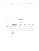
[0011] FIG. 2 depicts the blade 102 with a wear indicator 108 that is not worn down. Wear indicator 108 may be laser etching of the mark, a line pressed into the surface of the blade, dimples along a line, a scribe mark, paint, a material located inside of the product that becomes visible when the part to be replaced, or any other suitable indicator.
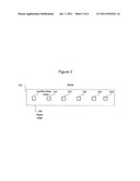
[0012] FIG. 3 depicts the blade 102 in which the blade edge 106 has worn down past the wear indicator 108.
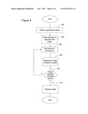
[0013] FIG. 4 depicts a flowchart of steps of an exemplary method for utilizing a wear indicator on a tool, in one implementation, may include the following steps and is discussed in conjunction with the blade 102 shown in FIG. 2. A replaceable blade, tool or tip 102 is obtained that may wear along a predetermined surface (e.g., blade edge 106) that can be easily visually inspected without the need for measuring equipment (step 402).
[0014] An easily identifiable wear indicator mark 108 is applied to the tool blade 102 on the surface, in the surface, built-up above the surface or placed upon the surface (step 404). In one implementation, the wear indicator mark 108 would be put on the tool 102 based on the recommended replacement time if the equipment is properly installed and adjusted. The wear indicator mark 108 may also be placed in such a manner as to leave a slight margin for error to help prevent damage to main equipment or tool. As discussed above, the wear indicator mark 108 may be formed in any suitable manner such as laser etching of the mark, a line pressed into the surface of the blade, dimples along a line, a scribe mark, paint, a material located inside of the product that becomes visible when the part to be replaced, or any other suitable manner.
[0015] Next, the tool blade 102 is used for its normal intended use (step 406). Then, the tool blade 102 is inspected to determine if the wear indicator mark 108 is visible (step 408). If the wear indicator mark is not visible (step 410), it is recommended to have the part(s) replaced to prevent damage. In the alternative case of the wear indicator mark 108 being placed in the tool blade 102, once it is visible, the part or parts need to be replaced to prevent damage and potentially facilitate quicker production times. If the wear indicator does not indicate sufficient wear, the blade may continued to be used normally (step 406). The tool blade 102 may then be replaced or repaired based on whether the mark is visible or not (step 412).
[0016] Methods and systems in accordance with the present invention may be used on any equipment that can be measured visually or needs to be measured for periodic replacement. The tools may be any tool with a blade or tip or other surface that can wear. The tools may be made of steel, any type of metal, plastic, aluminum or any other suitable materials.
[0017] The foregoing description of various embodiments provides illustration and description, but is not intended to be exhaustive or to limit the invention to the precise form disclosed. Modifications and variations are possible in light of the above teachings or may be acquired from practice in accordance with the present invention. It is to be understood that the invention is intended to cover various modifications and equivalent arrangements.
User Contributions:
Comment about this patent or add new information about this topic:
Images included with this patent application:
 |  |
 |  |
| Similar patent applications: | |
| Date | Title |
|---|---|
| 2011-02-10 | Tooth assembly and related method for releasably coupling a tooth to an adapter |
| 2011-06-16 | Snow removal and silage moving attachment device and method of use |
| 2011-09-01 | Material spreader for use with an excavator |
| 2008-10-30 | Automated control of boom or attachment for work vehicle to a preset position |
| 2008-10-30 | Automated control of boom or attachment for work vehicle to a preset position |
| New patent applications in this class: | |
| Date | Title |
|---|---|
| 2016-05-05 | Cutting edge attachment for snow plow |
| 2016-05-05 | Compact pulling apparatus |
| 2016-02-11 | Scraper blade device for cleaning a surface and method |
| 2015-11-05 | Curbstone deflector for a snow-clearing strip |
| 2014-12-25 | Elastomeric plow edge |
| New patent applications from these inventors: | |
| Date | Title |
|---|---|
| 2012-08-16 | Method and system for controlling a computer with a mobile device |
| Top Inventors for class "Excavating" | |
| Rank | Inventor's name |
|---|---|
| 1 | James Robert Lahood |
| 2 | Phillip J. Kunz |
| 3 | Robert N. Gamble, Ii |
| 4 | Mark D. Buckbee |
| 5 | Kent Winter |