Patent application title: SYSTEM AND METHOD FOR DENATURING AND FIXING COLLAGENOUS TISSUE
Inventors:
Edwin J. Hlavka (Palo Alto, CA, US)
Frederic H. Moll (Woodside, CA, US)
Robert G. Younge (Portola Valley, CA, US)
Robert G. Younge (Portola Valley, CA, US)
Daniel T. Wallace (Burlingame, CA, US)
Daniel T. Wallace (Burlingame, CA, US)
Assignees:
HANSEN MEDICAL, INC.
IPC8 Class: AA61B1804FI
USPC Class:
606 41
Class name: Instruments electrical application applicators
Publication date: 2011-06-30
Patent application number: 20110160724
Abstract:
A method for modifying a geometry of a collagenous tissue mass includes
heating the collagenous tissue mass to a temperature sufficient to cause
denaturation, and introducing a biocompatible fixative, such as genepin,
into the collagenous tissue mass.Claims:
1. A surgical method for repairing ligamentous tissue, comprising:
introducing an elongate instrument into a patient's body such that at
least a portion of the elongate instrument is positioned proximate the
ligamentous tissue; denaturing at least a portion of the ligamentous
tissue by delivering energy from an energy transmitting element on the
elongate instrument to the ligamentous tissue to shrink or tighten the
ligamentous tissue; and introducing a biocompatible fixative into the
denatured ligamentous tissue to retain the shrinkage or tightening of the
ligamentous tissue.
2. The method of claim 1, wherein the ligamentous tissue is a knee ligament.
3. The method of claim 2, wherein knee ligament is an anterior cruciate ligament.
4. The method of claim 1, wherein the ligamentous tissue is denatured by creating one or more lesions in the ligamentous tissue.
5. The method of claim 4, wherein a long linear lesion is created from a line of smaller lesions to provide an asymmetric tightening of the ligamentous tissue along a vector of the linear lesion.
6. The method of claim 4, wherein two or more long linear lesions are created from lines of smaller lesions to provide a symmetric tightening of the ligamentous tissue.
7. The method of claim 1, wherein the elongate instrument is robotically controlled, the elongate instrument being actuatable by an instrument driver in response to signals generated by manipulation of a controller.
8. The method of claim 1, wherein the energy transmitting element is an electrode for delivering radio frequency energy to heat the ligamentous tissue.
9. The method of claim 1, further comprising placing a limiter on an opposite side of the ligamentous tissue to prevent a needle, extending from the elongate instrument and used for delivering the fixative, from protruding beyond the ligamentous tissue to other tissue structures.
10. A surgical method for repairing ligamentous tissue in a subject's body, comprising: endoluminally advancing an elongate instrument to within a vicinity of the ligamentous tissue; heating the ligamentous tissue to a temperature sufficient to tighten the ligamentous tissue; and introducing a biocompatible fixative into the ligamentous tissue after heating the ligamentous tissue, to retain tightening of the ligamentous tissue.
11. The method of claim 10, wherein the ligamentous tissue is a knee ligament.
12. The method of claim 10, wherein the elongate instrument is robotically controlled.
13. A surgical method for repairing a lax anterior cruciate ligament, comprising: introducing an arthroscope into a patient's knee to access a workspace proximate the anterior cruciate ligament; introducing a treatment probe through a working lumen of the arthroscope, so that a distal end portion of the treatment probe extends out of a distal opening of the arthroscope proximate the ligament; using an energy transmitting element on the distal end portion of the treatment probe to create one or more lesions in the ligament; and introducing a biocompatible fixative into the respective one or more lesions.
14. The method of claim 13, wherein the energy transmitting element comprises a tissue surface contacting element.
15. The method of claim 13, wherein the energy transmitting element comprises a tissue penetrating element.
16. The method of claim 15, wherein the energy transmitting element comprises a needle electrode that extends out of the treatment probe, wherein the needle is used to deliver the fixative to the one or more lesions.
17. The method of claim 16, further comprising placing a limiter on an opposite side of the ligament to prevent the needle from protruding beyond the ligament to other tissue structures.
18. The method of claim 13, wherein a needle-less tip is utilized to inject the fixative into the one or more lesions.
19. The method of claim 13, wherein the fixative is applied topically to the one or more lesions.
20. The method of claim 13, wherein the elongate instrument is robotically controlled.
Description:
CROSS-REFERENCE TO RELATED APPLICATIONS
[0001] This application is a divisional of U.S. patent application Ser. No. 11/185,432 filed on Jul. 19, 2005, which claims the benefit under 35 U.S.C. §119 to U.S. Provisional Patent Application Nos. 60/678,097 filed May 4, 2005; 60/677,580 filed May 3, 2005; 60/644,505 filed Jan. 13, 2005; 60/600,869 filed Aug. 12, 2004 and 60/589,513 filed Jul. 19, 2004, The foregoing applications, along with U.S. patent application Ser. No. 11/176,957 filed Jul. 6, 2005 and U.S. patent application Ser. No. 11/073,363 filed Mar. 4, 2005, are hereby incorporated by reference into the present application in their entirety for all purposes.
FIELD OF INVENTION
[0002] The invention relates generally to catheter-based systems and method for treating tissue using controlled denaturation of collagen.
BACKGROUND
[0003] Referring to FIG. 1A, a collagenous tissue mass (327) is depicted. Collagen is one of the fundamental building blocks of the soft tissues of the human body. A collagenous tissue mass (327) typically comprises groupings of collagen fibrils (328) which are mechanically associated with each other by crosslinks (329), as depicted in the close-up view of FIG. 1B. Cross links (329) stiffen the overall mechanical properties of the tissue mass (327). Also shown in the close-up view of FIG. 1B is the triple helix structure (331) that typically comprises each of the collagen fibrils (328). As collagenous tissue is heated above about 60 degrees C., and thereby at least partially denatured, crosslinking bonds contributing to the mechanical and geometric association of the fibrils begin to break down, and normally linearly stretched out fibrils tend to recoil. Referring to FIG. 2A, a denatured collagenous tissue mass (335) is depicted comprising at least partially recoiled collagen fibrils (333) and some broken crosslinks (337) between previously coupled fibrils. The result of this transformation is a net overall reduction in geometry (339) of the denatured collagenous tissue mass (335). Along with this geometric change, the mechanical properties of the tissue mass change. The tissue may become weaker and more susceptible to creep deformation as it is loaded over time. Creep deformation under load can essentially reverse geometric gains achieved with procedures aimed at locally modifying tissue with collagen denaturation. In orthopaedic settings, for example, RF-based localized denaturation accomplished using devices from providers such as Oratec Interventions, Inc. and DePuy-Mitek, a Johnson & Johnson company, has been shown to be at least partially effective in the short term for tightening lax ligaments, but subsequent to loading over time, some ligament laxity may return, thereby decreasing the long-term effectiveness of the procedure. To address this challenge in such applications, immobilization and unloading of the targeted tissue may be a partial solution, but this solution also has well-known downsides. In summary, there is a heed for a solution to at least partially recover the properties of denatured collagenous tissue subsequent to denaturation treatment for geometric modification.
BRIEF DESCRIPTION OF THE DRAWINGS
[0004] FIGS. 1A-1B show a collagenous tissue mass.
[0005] FIG. 2A-2B show a denatured collagenous tissue mass.
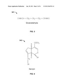
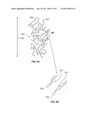
[0006] FIG. 3 shows the structure of glutaraldehyde.
[0007] FIG. 4 shows the structure of Genepin.
[0008] FIG. 5A-5C shows a denatured collagenous tissue mass after being exposed to Genepin.
[0009] FIG. 6 shows an experiment testing denaturation accompanied by Genepin treatment.
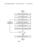
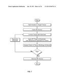
[0010] FIG. 7 shows a variation of a method for utilizing RF to denature tissue.
[0011] FIG. 8-9 show variations of a method for utilizing RF to denature tissue along with Genepin fixation treatment.
[0012] FIGS. 10A-10B shows variations of robotically controlled systems.
[0013] FIGS. 11A-H shows various hybrid distal tip structures for an elongate instrument.
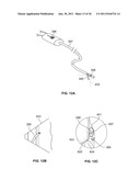
[0014] FIGS. 12A-C show variations of a system having a retractable injection needle extendable from the side of an elongate probe.
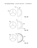
[0015] FIGS. 13A-C shows endoskeletons of the heart.
[0016] FIGS. 13D-E show various states of coaptation of a valve.
[0017] FIGS. 13F-G shows various prostheses for valves.
[0018] FIGS. 13H-L show various access approaches to a valve annulus or valve.
[0019] FIGS. 14A-C show access approaches to a valve annulus or valve via a coronary sinus.
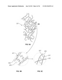
[0020] FIGS. 15A-B show localized denaturation for adjusting the position of chordae complexes.
[0021] FIGS. 16A-F show various systems for addressing deformation due to infarction.
[0022] FIGS. 17A-18D show various systems for treating various tissues.
DETAILED DESCRIPTION OF THE ILLUSTRATED EMBODIMENTS
[0023] A variety of chemicals known as "fixatives" have, in fact, been shown to improve the mechanical strength of collagenous tissue in certain states. Many fixatives, such as leather embalmers and formaldehyde, are known to be cytotoxic, and therefore may not be idea for in-situ application. A tissue fixative known as glutaraldehyde, the structure of which is depicted in FIG. 3 (341), has been used to fix graft tissues in xenograft, allograft, or autograft scenarios before implantation. Glutaraldehyde is also cytotoxic, and further, is known to induce undesirable calcification in certain scenarios, so careful rinsing techniques are generally utilized to remove such a fixative from the tissue subsequent to pre-implantation treatment. Some porcine mitral valve xenografts, for example, are treated with glutaraldehyde fixative and rinsed before implantation. Other chemical fixatives may be more biologically inert. Genepin, an extract of plant matter used historically in Chinese medicine, has also been used as a food dye because its tends to turn proteins a blue or purple color. Some academic studies have shown that genepin, the structure of which is depicted in FIG. 4 (343), may be 5,000 to 10,000 times less cytotoxic then gluteraldehyde.
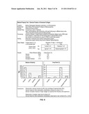
[0024] Referring to FIGS. 5A-C, a denatured collagenous tissue mass exposed to genepin (371) is depicted. When genepin is added to collagenous tissue, the double-ring structure of genepin associates with the fibrils (333) of the collagen to produce new crosslinks (375) between fibrils, as shown in FIG. 5B, and also new crosslinks (376) between the fibers (377) comprising the fibrils, as shown in FIG. 5C. The result is a partial recovery or recreation of the mechanical properties of collagenous tissue to the state that they were prior to denaturation. In other words, denaturation accompanied by genepin treatment may result in a geometrically modified, yet stable tissue mass which is less susceptible to creep deformation than denatured collgenous tissue without genepin treatment. Referring to FIG. 6, this has been experimentally confirmed in a study at the University of Pennsylvania, as directed by the inventors of the subject invention.
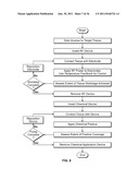
[0025] Referring to FIG. 7, one embodiment of a method for utilizing an RF device to locally denature collagenous tissue is depicted. A robotic catheter may be utilized to precisely access a targeted tissue structure, contact the targeted tissue structure with an RF electrode which my be coupled to the distal end of the robotic catheter, apply RF power to at least partially denature the subject tissue, and repeat as necessary to achieve a desired level of tissue shrinkage. Referring to FIGS. 8 and 9, embodiments utilizing genepin fixation treatment along with localized RF-induced denaturation to modify tissue geometry and recover or retain the mechanical properties of the tissue are depicted. FIG. 8 depicts an embodiment wherein a separate device is utilized to apply the denaturation treatment and genepin treatment, while FIG. 9 depicts an embodiment wherein a hybrid distal tip of the subject system may be utilized to apply both treatments without serial treatment using separate distal instrument tips for RF versus chemical fixation. Referring to FIG. 10A, a system comprising an operator control station (2), an instrument driver (16), a computer or processor (6), a display monitor (4), an elongate instrument (18) coupled to an electrode (378), and an RF energy control unit (379) is depicted. Such a system may be utilized for the embodiment depicted, for example, in FIG. 7. In alternative embodiments, other modalities may be utilized, such as ultrasound or microwave radiation, or heated fluids such as hot saline, to produce localized heating at the distal end of the elongate instrument (18) for denaturation of collagenated tissue. Referring to FIG. 10B, a similar system is depicted comprising an instrument driver (16) interfaced to an instrument set (28) comprising coaxially-interfaced sheath (30) and guide (18) instruments. The guide instrument (18) is coaxially interfaced, through its inner lumen, with an elongate probe (380) which may comprise a heating and/or injecting tool at its distal tip (381). In an embodiment comprising an injecting tip, a chemical injection system (382) may be proximally coupled to the instrument set (28) and configured to controllably deliver fluid, such as a genepin formulation, through the injecting tip distally.
[0026] Referring to FIG. 11A-H, various hybrid distal tip structures for an elongate instrument configured to both inject a chemical solution, such as a genepin solution or solution of another fixative, and also apply RF energy to induce localized denaturation are depicted. FIG. 11A depicts a needle-less injection port (384) positioned through the center of a monopolar RE electrode (383). FIG. 11B depicts a series of needle injection ports (385) located upon an RF electrode (383) for a voljimic injection into a broader volume that would be practicable with a single needle. FIG. 11c depicts an extensible/retractable needle (386) injection port through the center of an RF electrode (383). FIG. 11D depicts bipolar electrode configuration wherein each of two distal elements (387) comprises both an electrode and an injection tip. FIG. 11E depicts a single injection needle through the center of an RF electrode (383), the needle (388) comprising multiple fluid pathways (389) along its length to facilitate a distributed injection through a depth of targeted tissue. The needle (388) may he extensible/retractable, as with each of the distal tip needle structures depicted herein. FIG. 11F depicts an embodiment wherein an injection needle (391) is oriented through the center of a helical structure (390), and wherein any of the distal elements may be an RE electrode--in other words, the injection needle (391) or helical structure (390) may be a monopolar electrode, or each may be an electrode in a bipolar configuration. FIG. 11G depicts an embodiment wherein a bullet-shaped electrode (392) is positioned through at least a portion of a helical injection needle (393). FIG. 11H depicts an embodiment similar to that of FIG. 11G with the exception that a distal ring (394) comprises the electrode as opposed to the bullet-shaped electrode of FIG. 11G. The helical injection needles of the embodiments depicted in FIGS. 11G and 11H may have side ports (not shown) as depicted in the embodiment of FIG. 11E, and may comprise an electrode form a bipolar electrode configuration in association with the bullet-shaped electrode (392) or ring electrode (394).
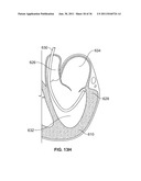
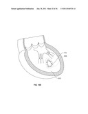
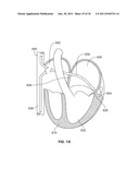
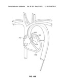
[0027] Referring to FIGS. 12A-C, a retractable injection needle (395) may be retractably extended from the side of an elongate probe (397) to provide access to tissue structures located to the periphery of a given probe orientation, such as the mitral annulus as oriented from the coronary sinus, as depicted in FIG. 12C. The injection needle (395) may he advanced and/or retracted utilizing a simple proximal mechanical lever (396), as depicted in FIG. 12A, or may be associated with an electromechanical configuration for precisely actuating advancement and/or retraction. To facilitate accurate positioning of a side-extending injector, or injector which also comprises an electrode in another embodiment, an imaging device (398), such as an ultrasound array, CCD device, or more conventional optical camera, in one embodiment comprising a mirror for side-oriented field of view (403), may be coupled to the probe (397) to provide a field of view (403) configured to capture images of at least a portion of the needle or needle/electrode as it is advanced out of the probe (397), as depicted in FIG. 12B. Referring to FIG. 12C, a partial cross sectional view of a system such as that depicted in FIGS. 12A and 12B is depicted with the probe (397) threaded down a coronary sinus (401) of a human heart, and an injection needle (395), in this embodiment also comprising an electrode, directed out of the coronary sinus (401) lumen and into the collagenous mitral valve annulus (604). The field of view (403) of the imaging device (398), in the depicted embodiment comprising an ultrasound transducer, is oriented to capture images of at least a portion of the needle (395), and preferably portions of surrounding identifiable tissues, such as the mitral annulus (604) or mitral valve leaflet (605).
[0028] Referring to FIGS. 13A-18D, several embodiments of systems and methods for minimally-invasive soft tissue shrinking interventions are depicted.
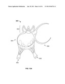
[0029] The inventive system may be utilized to address problems associated with mitral valve annulus deformation, such as mitral regurgitation. Referring to FIG. 13A, a structure which may be referred to as the "endoskeleton" of the heart is depicted (600), comprising three soft tissue backbones for the cusps of the aortic valve (602), the soft tissue backbone of the mitral valve annulus (604), pappilary muscle and chordae tendonae complexes (606), and the soft tissue backbone of a partial tricuspid valve annulus (608). Referring to FIG. 13B, an endoskeleton (600) is depicted in situ, surrounded by the anatomy of a normal human heart (610). The endoskeleton (600) may be described as a rather tough, gristle-like structure somewhat akin to the cartilage of the human ear. It is believed to hold the valves in position relative to each other and act as the primary load-bearing structure of the heart (610). Not by accident, it is the target destination of sutures placed by a surgeon utilizing conventional surgical techniques to address problems such as mitral valve deformation and associated functional mitral regurgitation, whereby there may be nothing intrinsically wrong with the mitral valve, but secondary to congestive heart failure, for example, the heart enlarges, pulling out the posterior leaflet of the mitral valve, thereby creating a lack of coaptation of the leaflets. Such coaptation problems generally are the result of deformation of the posterior aspect of the mitral annulus, as opposed to the anterior portion.
[0030] Referring to FIG. 13C, a subportion of an endoskeleton (600) is depicted at an angle to illustrate the curved posterior mitral annulus structure (604) versus the anterior aspect (611) of the mitral annulus structure, which comprises one of the central constructs of the endoskeleton (600). The aortic valve (602) annulus structure (626) is located opposite this central construct from the mitral valve (603).
[0031] Referring to FIG. 13D, a mitral valve (603) is depicted with good coaptation when closed. A well-coapted tricuspid valve (626) is also depicted. FIG. 13E depicts a similarly sized mitral valve (603) with a significant leaflet coaptation problem when closed, primarily due to deformation of the posterior aspect (622) of the mitral annulus, as opposed to significant deformation of the anterior aspect (611) of the mitral annulus. Such posterior mitral annulus deformation conventionally may be treated with installation of an annulus reshaping prosthesis, such as that depicted in FIG. 13F. Conventional prostheses for this purpose take many forms, including configurations such as that depicted in FIG. 13F, wherein the prosthesis only substantially supports the posterior aspect (622) of the mitral annulus, and configurations such as that depicted in FIG. 13G, wherein the prosthesis (621) supports substantially all of the mitral annulus. Referring to FIG. 13G, the depicted conventional prosthesis (621), such as those known as a "Carpintier ring", may be installed with a series of sutures (624) configured to gather and pull the posterior annulus (622) tissue anteriorly when the prosthesis (621) has been fastened into place. One of the challenges associated with such an installation is the invasiveness of the procedure. To address this challenge, the inventive instrument may be utilized to intravascularly approach the mitral annulus and treat the tissue to modify its geometry with minimal invasiveness relative to conventional open or port-based procedures.
[0032] Referring to FIG. 13H, an arterial access route is depicted whereby an elongate steerable instrument (630) such as that described above may be utilized to pass across the aortic valve (602), turn, and extend up toward the underside of the mitral annulus (628), thereby providing access to the underside, or inferior aspect, of the mitral valve annulus.
[0033] Referring to FIGS. 13I-J, a trans-septal approach to the superior aspect of the mitral annulus is depicted whereby an elongate steerable instrument (630) such as that described above may be utilized to pass across the right atrium (642) as it exits either the inferior (638) or superior (640) vena cava, cross the septum (636), and cross the left atrium (634) as it extends over to the top aspect (628) of the mitral valve annulus (604). Referring to FIG. 13J, a partial sectional view of structures similar to those depicted in FIG. 13I are depicted to illustrate that a steerable elongate instrument (630) with sufficient control and steerability may be used to contact various superior aspects (628) of the mitral valve annulus (604), from this trans-septal approach.
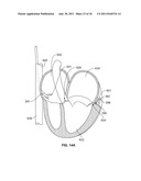
[0034] FIGS. 13K and 13L depict further detail regarding an underside approach to the mitral valve annulus such as that discussed in reference to FIG. 13H. Referring to FIG. 13K, utilizing an arterial retrograde approach (675) across the aortic valve (602), the aortic valve (602) shown split open in FIG. 13K, a steerable elongate instrument such as those described herein may follow one of three pathways (644, 646, 648) to access various aspects of the mitral annulus: to the left (644) of the papillary/chordae (606), to the right (648) of the papillary/chordae (606), or in between (646) the papillary/chordae (606). Referring to FIG. 13L, a schematic view illustrates that by utilizing the approaches depicted in FIG. 13K, a flexible elongate instrument (630) passed through the aortic valve (602) may access nearly all of the mitral valve annulus utilizing one of the three pathways (644, 646, 648) depicted in FIG. 13K, which are selected to avoid transverse motion and entanglement in the papillary/chordae (606) and other structures of the beating heart mitral valve (603) complex.
[0035] Thus superior/trans-septal and inferior/aortic approaches to the collagenous tissue structures of the mitral annulus, including but limited to the posterior aspect of the mitral annulus, are described in reference to FIGS. 13I-J, and 13H, J, and L. From each illustrated approach, a steerable elongate instrument may be utilized to access, denature, and/or chemically fix tissues of the mitral annulus utilizing distal tip hardware such as the embodiments described in reference to FIGS. 11A-H, and techniques such as those described in reference to FIGS. 7-9.
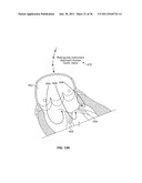
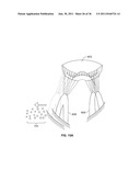
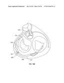
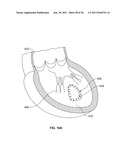
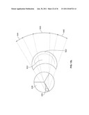
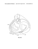
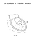
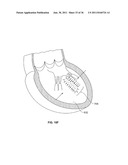
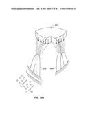
[0036] In another embodiment, a system comprising a probe configuration such as that depicted in FIGS. 12A-C may be utilized to cannulate the coronary sinus and access the collagenous tissue of the mitral valve by crossing out of the coronary sinus with a protruding needle device. Referring to FIG. 12A, a flexible probe instrument (397) may be directed into the coronary sinus (401) from the right atrium (642) and advanced through the coronary sinus (401) to place a advanceable/retractable injection and/or electrode needle (395) out the side of the probe (397), across the field of view of an imaging device (398), and into at least a portion of the collagenous tissue comprising the posterior mitral valve annulus (622), as depicted in FIG. 14B, where such collagenous tissue may be locally denatured and/or chemically fixed to provide retained tightening of the posterior annulus tissue, and preferably better coaptation of the mitral valve. As shown in FIG. 14C, the probe (397) may be advanced through the coronary sinus (401) to provide the needle (395) with a broad pattern (700) of access to portions of the posterior mitral annulus (622) to provide a series of localized shrinkings which together provide circumferential shrinking of the posterior mitral annulus (622), and thereby better mitral valve leaflet coaptation. Mitral regurgitation (not shown) may be observed with ultrasound as the posterior mitral annulus local shrinking is conducted, as depicted in FIG. 14C, for example, to provide the operator with realtime feedback as to the effectiveness of localized "tuning" and appropriate next steps during the operation.
[0037] Referring to FIG. 15A, a field of tissue lesions (701) treated by localized denaturation, chemical fixation, or both, may be utilized to slightly adjust the position of one of the papillary/chordae complexes (606) sideways relative to the mitral valve (603) to adjust valve coaptation. Similarly, as depicted in FIG. 15B, a differently-positioned field of tissue lesions (702) may be utilized to adjust the position of one of the papillary/chordae complexes (606) downward, or sideways and downward, relative to the mitral valve (603) position to adjust valve coaptation.
[0038] Referring to FIGS. 16A-F, a system similar to that described in reference to the denaturation/fixation processes for addressing mitral valve disease by directly modifying and fixing the geometry of the mitral valve tissue may be utilized to address localized deformation due to infarction, and thereby address associated mitral valve and/or left ventricular problems. Referring to FIG. 16A, a very typical position of a myocardial infarction is depicted. An initial infracted area is depicted (656), along with a post-infarct expansion area (658) into which the infarct generally may spread. Due to the localized stretching or spreading and tissue mechanics change associated with an infarction, along with the generally poor contractility of the infracted area, the heart may ultimately have a decreased injection fraction and increased left ventricular volume. To address this, a steerable elongate instrument with a distal tip configured to locally and precisely denature the collagenous tissue of the infarcted and noninfarcted myocardium, and/or fix the denatured tissue with a chemical fixative such as genepin, may be utilized. Such a system may be delivered to the left ventricle (632) through an arterial approach through the aortic valve (602), as depicted in FIG. 16B. FIG. 16c depicts the distal tip of the instrument (630) steering over to the targeted tissue surface and touching a localized target area where it may be used to induce a localized denaturation, preferably along with a localized injection of a fixative agent such as genepin, utilizing a probe distal tip such as those described in reference to FIGS. 11A-H. The shape of the post-infarct expansion area (658) is depicted. FIG. 16D depicts how a field (704) of closely related localized target areas for shrinkage and fixation treatment may be utilized to produce a net effect of shrinking an infarcted area to a minimized geometry (705), as depicted in FIG. 16E, wherein the net infarcted area after the treatment (705) is decreased from the original area of the infarct before the procedure. Referring to FIG. 16F, one or more linear series of localized denaturations and/or fixations (706) may be utilized to tune the relative positioning of the papillary complexes with or without the presence of an infarct. Myocardial tuning like this may be known as "left ventricular remodeling", and conventionally involves a series of imbrications generally formed with sutures in a substantially invasive and dangerous procedure. The subject catheter-based procedure provides a minimally invasive option.
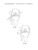
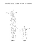
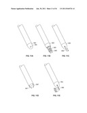
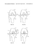
[0039] Referring to FIGS. 17A-18D, the inventive systems and techniques may be utilized to address other collagenous tissue interventions. For example, as depicted in FIGS. 17A-D, an arthroscope (709) and treatment probe (630) with a distal tip configured to denature and/or chemically fix collagenous tissue may be utilized to controllably shrink and/or fix a lax anterior cruciate ligament (711), positioned between the femur (707) and tibia (708) of the human knee. As depicted in FIG. 17A, a conventional arthroscope (709) may be introduced with conventional port access and saline-flushing technique. As depicted in FIG. 17B, a treatment probe (630) may be introduced as well, through a different port, to enable the operator to controllably contact the anterior cruciate ligament tissue and create lesions (710) in a desired pattern. In another embodiment, an arthroscope camera device may comprise the same minimally invasive elongate mechanical platform as the treatment probe, thus requiring only one surgical access port. Referring to FIG. 17C, a long linear lesion is created from a line of smaller lesions (711) to create an asymmetric tightening of the ligament along the vector of the linear lesion. Referring to FIG. 17D, two long linear lesions are created from lines of smaller lesions (710) to provide a more symmetric tightening of the ligament. Many distal tips may be utilized to create lesions within ligamentous tissue. For example, referring to FIG. 18A, a probe (630) comprising a needle tip may be utilized to create a deeper lesion within the ligament (711). Referring to FIG. 18B, a needle/electrode tip (714) may be utilized to denature and/or inject fixative precisely into the ligament (711). Referring to FIG. 18C, a probe embodiment similar to that depicted in FIG. 18B is depicted, with the exception that the embodiment of FIG. 18C also comprises a mechanical protrusion limiter structure (712) which may be placed around the opposite side of the subject ligament (711) to ensure that a needle protrusion to the limits of the limiter structure (712) crosses the entire ligament and not other tissue. Referring to FIG. 18D, a needle-less tip may be utilized for needle-less chemical fixative injection, topical fixative administration, and/or denaturing with an associated electrode.
[0040] While multiple embodiments and variations of the many aspects of the invention have been disclosed and described herein, such disclosure is provided for purposes of illustration only.
User Contributions:
Comment about this patent or add new information about this topic:
Images included with this patent application:
 |  |
 |  |
 |  |
 |  |
 |  |
 |  |
 |  |
 |  |
 |  |
 |  |
 |  |
 |  |
 |  |
 |  |
 |  |
 |  |
 |  |
 |  |
| New patent applications in this class: | |
| Date | Title |
|---|---|
| 2022-05-05 | Apparatus and method of assessing transvascular denervation |
| 2022-05-05 | Systems and methods for ablation using non-adjacent bipoles |
| 2022-05-05 | Needle tip to apply current, handpiece, and apparatus for treating skin |
| 2022-05-05 | Treatment apparatus and method of controlling same |
| 2022-05-05 | Arthroscopic devices and methods |
| New patent applications from these inventors: | |
| Date | Title |
|---|---|
| 2021-11-18 | Methods and devices for controlling a shapeable medical device |
| 2016-03-10 | Instrument systems and methods utilizing optical fiber sensor |
| 2015-06-11 | Robotic catheter system |
| 2014-12-04 | Methods and devices for controlling a shapeable medical device |
| 2014-10-02 | Robotic catheter system and methods |
| Top Inventors for class "Surgery" | |
| Rank | Inventor's name |
|---|---|
| 1 | Lutz Biedermann |
| 2 | Roger P. Jackson |
| 3 | Wilfried Matthis |
| 4 | Frederick E. Shelton, Iv |
| 5 | Joseph D. Brannan |