Patent application title: Screw Pump with Anti-Turbulent Structure
Inventors:
Ding-Kuey Liu (Taipei Hsien, TW)
Chao-Hua Tung (Taipei Hsien, TW)
Assignees:
SUNNY KING MACHINERY CO., LTD.
IPC8 Class: AF04C216FI
USPC Class:
418202
Class name: Interengaging rotating members helical or herringbone each member having opposed axially spaced helices
Publication date: 2011-06-30
Patent application number: 20110158841
Abstract:
A screw pump with anti-turbulent structure has a housing, at least two
screw rotors parallelly mounted through the housing and engaging with
each other, and a partition disposed around the at least two screw rotor.
The partition may have at least two circular walls respectively formed
around the rotors and an annular protrusion formed on an inner surface of
the housing and being adjacent to and kept from contacting the at least
two circular walls, and may be a panel having at least two mounting holes
respectively mounted around the rotors. Fluids flowing in opposite
directions are divided by the partition and do not encounter each other
and do not become turbulent. Consequently, pressurizing efficiency of the
screw pump is improved.Claims:
1. A screw pump comprising a housing having an inlet formed in and
communicating the housing; and an outlet formed in and communicating the
housing; at least two screw rotors axially and parallelly mounted
rotatably through the housing, each screw rotor having two threaded parts
formed around the screw rotor and being respectively right-hand threaded
and left-hand threaded, and each threaded part engaging a corresponding
threaded part of the other one of the at least two screw rotors; and a
partition mounted in the housing, disposed around the at least two screw
rotors and between the threaded parts of each screw rotor and having at
least two circular walls respectively formed around the at least two
screw rotors and being adjacent to and kept from contacting each other.
2. The screw pump as claimed in claim 1, wherein the housing further has a mounting tube axially formed on an inner surface of the housing and having an annular recess formed in and around an inner wall of the mounting tube; the outlet of the housing is formed in the housing and the mounting tube and communicates with the mounting tube and corresponds to the annular recess of the mounting tube; the at least two screw rotors are mounted through the mounting tube; and the partition is mounted in the mounting tube and further has an annular protrusion formed on the inner wall of the mounting tube in the annular recess and being adjacent to and kept from contacting the at least two circular walls.
3. A screw pump comprising a housing having an inlet formed in and communicating the housing; and an outlet formed in and communicating the housing; at least two screw rotor axially and parallelly mounted rotatably through the housing, each screw rotor having two threaded parts formed around the screw rotor and being respectively right-hand threaded and left-hand threaded, and each threaded part engaging a corresponding threaded part of the other one of the at least two screw rotors; and a partition mounted in the housing, disposed around the at least two screw rotors and between the threaded parts of each screw rotor, being a panel having at least two mounting holes formed through the partition and respectively mounted around the at least two rotors, and each mounting hole having an inner edge respectively defined around the mounting holes and being adjacent to and kept from contacting a corresponding one of the at least two screw rotors.
4. The screw pump as claimed in claim 1, wherein the housing further has a mounting tube axially formed on an inner surface of the housing and having an annular recess formed in and around an inner wall of the mounting tube; the outlet of the housing is formed in the housing and the mounting tube and communicates with the mounting tube and corresponds to the annular recess of the mounting tube; and the at least two screw rotors are mounted through the mounting tube.
Description:
BACKGROUND OF THE INVENTION
[0001] 1. Field of the Invention
[0002] The present invention relates to a screw pump, especially to a screw pump with an anti-turbulent structure to prevent pressurized fluid from becoming turbulent.
[0003] 2. Description of the Prior Art(s) A pump transfers mechanical work to fluids, such as liquids or gases, to change states (ex: height, pressure . . . etc.) of the fluid to move the fluids.
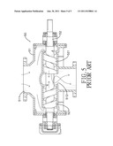
[0004] With reference to FIG. 5, a conventional screw pump (50) comprises a housing (51) having an inlet (511) and an outlet (512), and two screw rotors (52) axially and parallelly mounted rotatably through the housing (51). Each screw rotor (52) has two threaded parts (521) respectively engaging the threaded parts (521) of the other screw rotor (52). Thus, when one of the screw rotor (52) is rotated, the other screw rotor (52) rotates simultaneously. A confluence is defined between the threaded parts (521) of each screw rotor (52) and corresponds to the outlet (512) of the housing (52). When the fluids flow through the inlet (511) and into the housing (51) and one of the screw rotor (52) is driven by a motor, the threaded parts (521) of the screw rotors (52) force the fluid toward the confluence and flow out of the housing (51) from the outlet (512).
[0005] However, since the threaded parts (521) of the screw rotors (52) move the fluids in reverse directions, the fluids encounter each other and become turbulent in the confluence of the rotors (52). Thus, pressures of the fluids are reduced and pressurizing efficiency of the conventional screw pump (50) is low and cannot be efficiently raised.
[0006] To overcome the shortcomings, the present invention provides a screw pump with an anti-turbulent structure to mitigate or obviate the aforementioned problems.
SUMMARY OF THE INVENTION
[0007] The main objective of the present invention is to provide a screw pump with an anti-turbulent structure.
[0008] The screw pump has a housing, at least two screw rotors parallelly mounted through the housing and engaging with each other, and a partition disposed around the at least two screw rotor. The partition may have at least two circular walls respectively formed around the rotors and an annular protrusion formed on an inner surface of the housing and being adjacent to and kept from contacting the at least two circular walls, and may be a panel having at least two mounting holes respectively mounted around the rotors.
[0009] Fluids flowing in opposite directions are divided by the partition and do not encounter each other and do not become turbulent. Consequently, pressurizing efficiency of the screw pump is improved.
[0010] Other objectives, advantages and novel features of the invention will become more apparent from the following detailed description when taken in conjunction with the accompanying drawings.
BRIEF DESCRIPTION OF THE DRAWINGS
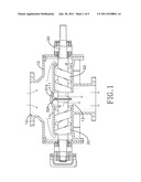
[0011] FIG. 1 is a side view in partial section of a screw pump with an anti-turbulent structure in accordance with the present invention;
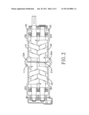
[0012] FIG. 2 is a top view in partial section of the screw pump in FIG. 1;
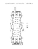
[0013] FIG. 3 is a top view in partial section of another embodiment of a screw pump with an anti-turbulent structure in accordance with the present invention;
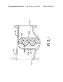
[0014] FIG. 4 is a cross-sectional end view of the screw pump in FIG. 3; and
[0015] FIG. 5 is a side view in partial section of a conventional screw pump in accordance with the prior art.
DETAILED DESCRIPTION OF THE PREFERRED EMBODIMENTS
[0016] With reference to FIGS. 1 to 3, a screw pump with an anti-turbulent structure in accordance with the present invention comprises a housing (10), at least two screw rotors (20) and a partition (30A, 30B).
[0017] The housing (10) is substantially cylindrical and has a mounting tube (11), an inlet (12) and an outlet (13). The mounting tube (11) is axially formed on an inner surface of the housing (10) and has an annular recess (111). The annular recess (111) is formed in and around an inner wall of the mounting tube (11). The inlet (12) is formed in and communicates with the housing (10). The outlet (13) is formed in and communicates with the housing (10), may be formed in the housing (10) and the mounting tube (11), may be communicates with the mounting tube (11) and may correspond to the annular recess (111) of mounting tube (11).
[0018] The at least two screw rotors (20) are axially and parallelly mounted rotatably through the housing (10) and may be mounted through the mounting tube (11). Each screw rotor (20) has two threaded parts (22). The threaded parts (22) are formed around the screw rotor (20) and are respectively right-hand threaded and left-hand threaded. Each threaded part (22) engages a corresponding threaded part (22) of the other one of the at least two screw rotors (20).
[0019] A confluence is defined between the threaded parts (22) of the at least two screw rotors (20). Thus, as one of the at least two rotors (20) rotates, the other of the at least two screw rotors (20) rotates simultaneously. When fluids flow through the inlet (12) and into the housing (10) and one of the at least two screw rotors (20) is driven by a motor, the threaded parts (22) force the fluids from two opposite ends of the housing (10) or from two opposite ends of the mounting tube (11) toward the confluence and pressurize the fluids.
[0020] The partition (30A, 30B) is mounted in the housing (10), may be mounted in the mounting tube (11), is disposed around the at least two screw rotors (20) and between the threaded parts (22) of each screw rotor (20) and divides the confluence into two individual spaces. Therefore, the pressurized fluids flowing in opposite directions respectively flow along the partition (30A, 30B) and out of the housing (10) from the outlet (13).
[0021] The partition (30A) may have at least two circular walls (31A) and an annular protrusion (32A). The at least two circular walls (31A) are respectively formed around the at least two screw rotors (20) and are adjacent to and are kept from contacting each other. The annular protrusion (32A) is formed on the inner wall of the mounting tube (11) in the annular recess (111) and is adjacent to and is kept from contacting the at least two circular walls (31A) so the at least two rotors (20) can rotate smoothly.
[0022] With further reference to FIGS. 3 and 4, the partition (30B) may be a panel, may be composed of two halves (30B') and has at least two mounting holes (33B). The at least two mounting holes (33B) are formed through the partition (30B) and are respectively mounted around the at least two rotors (20). Each mounting hole (33B) has an inner edge. The inner edge of the mounting hole (33B) is defined around the mounting holes (33B) and is adjacent to and is kept from contacting a corresponding one of the at least two screw rotors (20) so the at least two rotors (20) can rotate smoothly.
[0023] The screw pump with anti-turbulent structure as described has the following advantage. Since the partition (30A, 30B) divides the confluence into two individual spaces, the fluids flow in opposite directions do not encounter each other and do not become turbulent in the confluence. Consequently, pressurizing efficiency of the screw pump is improved.
[0024] Even though numerous characteristics and advantages of the present invention have been set forth in the foregoing description, together with details of the structure and features of the invention, the disclosure is illustrative only. Changes may be made in the details, especially in matters of shape, size, and arrangement of parts within the principles of the invention to the full extent indicated by the broad general meaning of the terms in which the appended claims are expressed.
User Contributions:
Comment about this patent or add new information about this topic:
Images included with this patent application:
 |  |
 |  |
 |
| New patent applications in this class: | |
| Date | Title |
|---|---|
| 2018-01-25 | Oil-flooded screw compressor system and method for modifying the same |
| 2014-07-31 | Double-helical gear rotary positive displacement pump |
| 2012-03-08 | Screw compressor with economizer |
| Top Inventors for class "Rotary expansible chamber devices" | |
| Rank | Inventor's name |
|---|---|
| 1 | Byeongchul Lee |
| 2 | Masanori Masuda |
| 3 | Robert C. Stover |
| 4 | Masao Akei |
| 5 | Rene Schepp |