Patent application title: 3D AUDIO DELIVERY ACCOMPANYING 3D DISPLAY SUPPORTED BY VIEWER/LISTENER POSITION AND ORIENTATION TRACKING
Inventors:
Nambirajan Seshadri (Irvine, CA, US)
Jeyhan Karaoguz (Irvine, CA, US)
James D. Bennett (Hroznetin, CZ)
Assignees:
BROADCOM CORPORATION
IPC8 Class: AH04N1304FI
USPC Class:
348 51
Class name: Television stereoscopic stereoscopic display device
Publication date: 2011-06-30
Patent application number: 20110157327
Abstract:
Techniques are described herein for supporting 3D audio delivery
accompanying 3D display supported by viewer/listener position and
orientation tracking. For example, audio content is configured to have a
spatial orientation that accords with an orientation of a viewer. A
spatial orientation of audio content is a configuration of the audio
content in which characteristics of respective portions of the audio
content, which correspond to respective speakers, indicate an orientation
of ears of a viewer/listener with respect to sound source(s) that
correspond to (e.g., are depicted in) a three-dimensional view. Such a
characteristic may include an amplitude of sound that corresponds to a
sound source and/or a delay associated with the sound that corresponds to
the sound source.Claims:
1. A method supporting a viewer of a three-dimensional visual
presentation within a premises, the viewer having a first orientation
within the premises, the method comprising: identifying at least one
positional characteristic relating to the first orientation of the viewer
within the premises; delivering a video output, tailored based at least
in part on the at least one positional characteristic, for the
three-dimensional visual presentation to the viewer in the first
orientation; and delivering an audio output, tailored based at least in
part on the at least one positional characteristic, to audibly supplement
the video output for the viewer in the first orientation.
2. The method of claim 1, wherein the at least one positional characteristic comprising a relative location of the viewer.
3. The method of claim 1, wherein the at least one positional characteristic comprising an orientation of a head of the viewer.
4. The method of claim 1, further comprising tailoring the audio output based at least in part on the at least one positional characteristic.
5. The method of claim 4, wherein the tailoring of the audio output comprising selecting the audio output from a plurality of audio outputs.
6. The method of claim 4, wherein the tailoring of the audio output comprising generating the audio output.
7. The method of claim 1, wherein the audio output is tailored by changing at least an output amplitude.
8. The method of claim 1, wherein the audio output is tailored by adding a delay.
9. Media circuitry supporting a viewer of a three-dimensional visual presentation within a premises, the viewer having a first orientation within the premises, the media circuitry comprising: first circuitry that identifies at least one positional characteristic relating to the first orientation of the viewer within the premises; second circuitry that delivers a video output for the three-dimensional visual presentation to the viewer in the first orientation; and third circuitry that delivers an audio output that is tailored based at least in part on the at least one positional characteristic, the audio output supplementing the video output for the viewer in the first orientation.
10. The media circuitry of claim 9, wherein the at least one positional characteristic comprising a relative location of the viewer.
11. The media circuitry of claim 9, wherein the at least one positional characteristic comprising an orientation of a head of the viewer.
12. The media circuitry of claim 9, further comprising fourth circuitry that performs the tailoring of the audio output.
13. The media circuitry of claim 12, wherein the fourth circuitry performs the tailoring by selecting the audio output from a plurality of audio outputs.
14. The media circuitry of claim 12, wherein the fourth circuitry performs the tailoring by changing at least an output amplitude.
15. The media circuitry of claim 12, wherein the fourth circuitry performs the tailoring by adding a delay.
16. The media circuitry of claim 12, wherein the fourth circuitry performs the tailoring based at least in part on image data captured within the premises.
17. The media circuitry of claim 12, wherein the fourth circuitry performs the tailoring based at least in part on captured audio data captured within the premises.
18. The media circuitry of claim 12, further comprising fifth circuitry that is carried by the viewer, the fifth circuitry assisting the first circuitry in the identification of the at least one positional characteristic.
19. A method relating to delivery of an audio experience for ears of a listener via a plurality of speakers, the audio experience to be established based on audio output that is based on audio content, the audio content having a spatial orientation, the listener being at a first location, the ears of the listener being in either a first orientation or a second orientation with respect to the plurality of speakers, the method comprising: detecting the ears of the listener being in the first orientation with respect to the plurality of speakers; delivering first audio output to attempt to establish, with the spatial orientation of the audio content, the audio experience for the ears of the listener in the first orientation; detecting the ears of the listener being in the second orientation with respect to the plurality of speakers; and delivering second audio output to attempt to establish, with the spatial orientation of the audio content, the audio experience for the ears of the listener in the second orientation.
20. The method of claim 19, further comprising: detecting a move by the listener to a second location; and delivering third audio output to establish, with the spatial orientation of the audio content, the audio experience for the ears of the listener at the second location.
21. The method of claim 19, further comprising: delivering a three-dimensional visual presentation that is tailored based on the listener being at the first location.
Description:
CROSS-REFERENCE TO RELATED APPLICATIONS
[0001] This application claims the benefit of U.S. Provisional Application No. 61/291,818, filed on Dec. 31, 2009, which is incorporated by reference herein in its entirety.
[0002] This application also claims the benefit of U.S. Provisional Application No. 61/303,119, filed on Feb. 10, 2010, which is incorporated by reference herein in its entirety.
[0003] This application is also related to the following U.S. Patent Applications, each of which also claims the benefit of U.S. Provisional Patent Application Nos. 61/291,818 and 61/303,119 and each of which is incorporated by reference herein:
[0004] U.S. patent application Ser. No. 12/774,225, filed on May 5, 2010 and entitled "Controlling a Pixel Array to Support an Adaptable Light Manipulator";
[0005] U.S. patent application Ser. No. 12/774,307, filed on May 5, 2010 and entitled "Display with Elastic Light Manipulator";
[0006] U.S. patent application Ser. No. 12/845,409, filed on Jul. 28, 2010, and entitled "Display with Adaptable Parallax Barrier";
[0007] U.S. patent application Ser. No. 12/845,440, filed on Jul. 28, 2010, and entitled "Adaptable Parallax Barrier Supporting Mixed 2D and Stereoscopic 3D Display Regions";
[0008] U.S. patent application Ser. No. 12/845,461, filed on Jul. 28, 2010, and entitled "Display Supporting Multiple Simultaneous 3D Views";
[0009] U.S. patent application Ser. No. ______ (Attorney Docket. No. A05.01210000), filed on even date herewith and entitled "Backlighting Array Supporting Adaptable Parallax Barrier";
[0010] U.S. patent application Ser. No. ______ (Attorney Docket No. A05.01240000), filed on even date herewith and entitled "Coordinated Driving of Adaptable Light Manipulator, Backlighting and Pixel Array in Support of Adaptable 2D and 3D Displays";
[0011] U.S. patent application Ser. No. ______ (Attorney Docket No. A05.01390000), filed on even date herewith and entitled "Three-Dimensional Display System With Adaptation Based on Viewing Reference of Viewer(s)";
[0012] U.S. patent application Ser. No. ______ (Attorney Docket No. A05.01400000), filed on even date herewith and entitled "Remote Control with Integrated Position, Viewer Identification and Optical and Audio Test"; and
[0013] U.S. patent application Ser. No. ______ (Attorney Docket No. A05.01420000), filed on even date herewith and entitled "Multiple Remote Controllers that Each Simultaneously Controls a Different Visual Presentation of a 2D/3D Display."
BACKGROUND OF THE INVENTION
[0014] 1. Field of the Invention
[0015] The present invention generally relates to techniques for delivering audio to a listener based on an orientation of the listener.
[0016] 2. Background Art
[0017] Images may be generated for display in various forms. For instance, television (TV) is a widely used telecommunication medium for transmitting and displaying images in monochromatic ("black and white") or color form. Conventionally, images are provided in analog form and are displayed by display devices in two-dimensions. More recently, images are being provided in digital form for display in two-dimensions on display devices having improved resolution (e.g., "high definition" or "HD"). Even more recently, images capable of being displayed in three-dimensions are being generated.
[0018] Conventional displays may use a variety of techniques to achieve three-dimensional image viewing functionality. For example, various types of glasses have been developed that may be worn by users to view three-dimensional images displayed by a conventional display. Examples of such glasses include glasses that utilize color filters or polarized filters. In each case, the lenses of the glasses pass two-dimensional images of differing perspective to the user's left and right eyes. The images are combined in the visual center of the brain of the user to be perceived as a three-dimensional image. In another example, synchronized left eye, right eye LCD (liquid crystal display) shutter glasses may be used with conventional two-dimensional displays to create a three-dimensional viewing illusion. In still another example, LCD display glasses are being used to display three-dimensional images to a user. The lenses of the LCD display glasses include corresponding displays that provide images of differing perspective to the user's eyes, to be perceived by the user as three-dimensional.
[0019] Problems exist with such techniques for viewing three-dimensional images. For instance, persons that use such displays and systems to view three-dimensional images may suffer from headaches, eyestrain, and/or nausea after long exposure. Furthermore, some content, such as two-dimensional text, may be more difficult to read and interpret when displayed three-dimensionally. To address these problems, some manufacturers have created display devices that may be toggled between three-dimensional viewing and two-dimensional viewing. A display device of this type may be switched to a three-dimensional mode for viewing of three-dimensional images, and may be switched to a two-dimensional mode for viewing of two-dimensional images (and/or to provide a respite from the viewing of three-dimensional images).
[0020] A parallax barrier is another example of a device that enables images to be displayed in three-dimensions. A parallax barrier includes a layer of material with a series of precision slits. The parallax barrier is placed proximal to a display so that a user's eyes each see a different set of pixels to create a sense of depth through parallax. A disadvantage of parallax barriers is that the viewer must be positioned in a well-defined location in order to experience the three-dimensional effect. If the viewer moves his/her eyes away from this "sweet spot," image flipping and/or exacerbation of the eyestrain, headaches and nausea that may be associated with prolonged three-dimensional image viewing may result. Conventional three-dimensional displays that utilize parallax barriers are also constrained in that the displays must be entirely in a two-dimensional image mode or a three-dimensional image mode at any time.
[0021] One common technique for improving an audio experience of viewers of two-dimensional display devices is referred to as "surround sound". Surround sound provides different audio content through different audio channels in an effort to provide a fixed or forward perspective of a sound field to a viewer/listener at a fixed location (e.g., the aforementioned "sweet spot"). The audio channels correspond to locations of speakers that surround the viewer (e.g., right, left, front, back, etc.). However, surround sound has its limitations, especially when applied with respect to three-dimensional display devices. For example, if a viewer moves away from the fixed location, a degradation of the viewer's audio experience may result. For instance, as a viewer moves about a room, the sound that is projected from a speaker may be perceived as becoming louder as the viewer nears that speaker. The sound that is projected from that speaker may be perceived as becoming quieter as the viewer moves away from the speaker. If the viewer is wearing a viewer-specific audio device (e.g., headphones or earbuds), movements by the viewer may have no effect on the viewer's perception of the sounds that are projected from speakers in the viewer-specific device.
BRIEF SUMMARY OF THE INVENTION
[0022] Methods, systems, and apparatuses are described for supporting 3D audio delivery accompanying 3D display supported by viewer/listener position and orientation tracking as shown in and/or described herein in connection with at least one of the figures, as set forth more completely in the claims.
BRIEF DESCRIPTION OF THE DRAWINGS/FIGURES
[0023] The accompanying drawings, which are incorporated herein and form a part of the specification, illustrate the present invention and, together with the description, further serve to explain the principles of the invention and to enable a person skilled in the pertinent art to make and use the invention.
[0024] FIG. 1A is a block diagram of a media system in accordance with an embodiment.
[0025] FIG. 1B shows an exemplary content capturing system in accordance with an embodiment.
[0026] FIG. 2 shows an exemplary viewer-located implementation of an audio system shown in FIG. 1 in accordance with an embodiment.
[0027] FIG. 3 is a block diagram of a media system in accordance with a first embodiment that includes reference information generation circuitry that implements a triangulation technique to determine an estimated location of a viewer.
[0028] FIG. 4 is a block diagram of a media system in accordance with a second embodiment that includes reference information generation circuitry that implements a triangulation technique to determine an estimated location of a viewer.
[0029] FIG. 5 is a block diagram of a media system in accordance with an embodiment that includes reference information generation circuitry that implements an infrared (IR) distance measurement system to help determine an estimated location of a viewer.
[0030] FIG. 6 is a block diagram of a media system in accordance with an embodiment that includes information generation circuitry that implements a magnetic field detection system to help determine an estimated location of viewer.
[0031] FIG. 7 is a block diagram of a media system in accordance with an embodiment that includes viewer-located reference information generation circuitry that includes one or more cameras and one or more microphones for facilitating the generation of reference information corresponding to at least one positional characteristic of a viewing reference of a viewer.
[0032] FIG. 8 is a block diagram of a media system in accordance with an embodiment that includes reference information generation circuitry that includes a head orientation sensor and eye tracking circuitry for determining a head orientation and point of gaze, respectively, of a viewer.
[0033] FIG. 9 is a block diagram of a media system in accordance with an embodiment in which non-viewer-located camera(s) and/or microphone(s) operate to generate reference information corresponding to at least one positional characteristic of a viewing reference of a viewer.
[0034] FIG. 10 depicts a headset in accordance with an embodiment that includes reference information generation circuitry for facilitating the generation of reference information corresponding to at least one positional characteristic of a viewing reference of a viewer.
[0035] FIG. 11A depicts an embodiment in which reference information generation circuitry is distributed among a headset and a remote control that are connected to each other by a wired communication link.
[0036] FIG. 11B depicts an embodiment in which reference information generation circuitry is distributed among a headset and a laptop computer that are connected to each other by a wireless communication link.
[0037] FIG. 12 depicts a flowchart of a method for presenting three-dimensional content to a viewer having a viewing reference in accordance with an embodiment, wherein the manner in which such content is presented is controlled in accordance with reference information concerning the viewing reference.
[0038] FIG. 13 depicts a flowchart of a method for delivering video output and audio output to a viewer based at least in part on positional characteristic(s) relating to an orientation of the viewer in accordance with an embodiment.
[0039] FIG. 14 depicts a flowchart of a method for delivering an audio experience for ears of a listener via a plurality of speakers in accordance with an embodiment.
[0040] FIG. 15 is a block diagram of a media system in accordance with an embodiment that simultaneously presents first three-dimensional content to a first viewer having a first viewing reference and second three-dimensional content to a second viewer having a second viewing reference, wherein the manner in which such content is displayed is controlled in accordance with reference information concerning the first and second viewing references.
[0041] FIG. 16 depicts a flowchart of a method for presenting first three-dimensional content to a first viewer having a first viewing reference and simultaneously presenting second three-dimensional content to a second viewer having a second reference in accordance with an embodiment, wherein the manner in which such content is presented is controlled in accordance with reference information concerning the first and second viewing references.
[0042] FIG. 17 depicts a flowchart of a method for delivering audio content to first and second viewers of a display capable of simultaneously presenting first video content to the first viewer and second video content to the second viewer in accordance with an embodiment.
[0043] FIG. 18 is a block diagram of an example implementation of an adaptable two-dimensional/three-dimensional media system in accordance with an embodiment.
[0044] The present invention will now be described with reference to the accompanying drawings. In the drawings, like reference numbers indicate identical or functionally similar elements. Additionally, the left-most digit(s) of a reference number identifies the drawing in which the reference number first appears.
DETAILED DESCRIPTION OF THE INVENTION
I. Introduction
[0045] The present specification discloses one or more embodiments that incorporate the features of the invention. The disclosed embodiment(s) merely exemplify the invention. The scope of the invention is not limited to the disclosed embodiment(s). The invention is defined by the claims appended hereto.
[0046] References in the specification to "one embodiment," "an embodiment," "an example embodiment," etc., indicate that the embodiment described may include a particular feature, structure, or characteristic, but every embodiment may not necessarily include the particular feature, structure, or characteristic. Moreover, such phrases are not necessarily referring to the same embodiment. Further, when a particular feature, structure, or characteristic is described in connection with an embodiment, it is submitted that it is within the knowledge of one skilled in the art to effect such feature, structure, or characteristic in connection with other embodiments whether or not explicitly described.
[0047] Furthermore, it should be understood that spatial descriptions (e.g., "above," "below," "up," "left," "right," "down," "top," "bottom," "vertical," "horizontal," etc.) used herein are for purposes of illustration only, and that practical implementations of the structures described herein can be spatially arranged in any orientation or manner.
II. Example Three-Dimensional Media Systems with Adaptation Based on Viewer Orientation
[0048] FIG. 1 is a block diagram of a media system 102 that presents three-dimensional content to a viewer 106 having a viewing reference 108 (i.e., an orientation) in accordance with an embodiment. As shown in FIG. 1, media system 102 includes an adaptable screen assembly 122, driver circuitry 124, processing circuitry 126, reference information generation circuitry 110a, and reference information generation circuitry 110b.
[0049] Generally speaking, media system 102 operates to deliver light that includes one or more viewable images to a viewing area that includes viewer 106. Media system 102 also operates to deliver audio content that is associated with the one or more viewable images toward viewer 106. Media system 102 may include, for example and without limitation, a television, a projection system, a home theater system, a monitor, a computing device (e.g., desktop computer, laptop computer, tablet computer) or a handheld device (e.g., a cellular phone, smart phone, personal media player, personal digital assistant), wherein the computing device or handheld device has at least one attached or integrated display.
[0050] Adaptable screen assembly 122 is designed such that certain display characteristics associated therewith can be modified to support multiple viewing modes. For example, certain display characteristics associated with adaptable screen assembly 122 may be modified to selectively present images in a two-dimensional viewing mode or one or more three-dimensional viewing modes. For example, in certain implementations, display characteristics associated with screen assembly 122 may be modified to display a single image of certain subject matter to provide a two-dimensional view thereof, to display two images of the same subject matter viewed from different perspectives in a manner that provides a single three-dimensional view thereof, or to display a multiple of two images (e.g., four images, eight images, etc.) of the same subject matter viewed from different perspectives in a manner that simultaneously provides multiple three-dimensional views thereof, wherein the particular three-dimensional view perceived by a viewer is dependent at least in part upon the position of the viewer (also referred to herein as a "multi-view three-dimensional viewing mode").
[0051] Various examples of adaptable screen assemblies that can be modified to support such two-dimensional and three-dimensional viewing modes are described in the following commonly-owned, co-pending U.S. Patent Applications: U.S. patent application Ser. No. 12/774,307, filed on May 5, 2010 and entitled "Display with Elastic Light Manipulator"; U.S. patent application Ser. No. 12/845,409, filed on Jul. 28, 2010 and entitled "Display with Adaptable Parallax Barrier"; and U.S. patent application Ser. No. 12/845,461, filed on Jul. 28, 2010 and entitled "Display Supporting Multiple Simultaneous 3D Views." The entirety of each of these applications is incorporated by reference herein. Adaptable screen assembly 122 may be implemented in accordance with descriptions provided in the above-referenced applications.
[0052] In addition to the foregoing capabilities, adaptable screen assembly 122 may also be capable of simultaneously presenting two dimensional views and three-dimensional views in different regions of the same screen, respectively. By way of example, adaptable screen assembly 122 may be capable of simultaneously presenting a two-dimensional view of first visual content in a first region of a screen, and one or more three-dimensional views of second visual content in a second region of the screen. Adaptable screen assemblies having such capabilities are described in commonly-owned, co-pending U.S. patent application Ser. No. 12/845,440, filed on Jul. 28, 2010, and entitled "Adaptable Parallax Barrier Supporting Mixed 2D and Stereoscopic 3D Display Regions," the entirety of which is incorporated by reference herein.
[0053] A display characteristic of adaptable screen assembly 122 that may be modified to switch between different full-screen and regional two-dimensional and three-dimensional viewing modes may include a configuration of an adaptable light manipulator such as an adaptable parallax barrier. An adaptable lenticular lens may also be used as an adaptable light manipulator to switch between different full-screen three-dimensional viewing modes. Descriptions of such adaptable light manipulators and methods for dynamically modifying the same may be found in the aforementioned, incorporated U.S. patent application Ser. No. 12/774,307, filed on May 5, 2010 and entitled "Display with Elastic Light Manipulator" and U.S. patent application Ser. No. 12/845,409, filed on Jul. 28, 2010 and entitled "Display with Adaptable Parallax Barrier." For example, the degree of stretching of an adaptable lenticular lens may be modified in order to support certain three-dimensional viewing modes. As another example, barrier elements of an adaptable parallax barrier may be selectively placed in a blocking or non-blocking state in order to support certain full-screen and regional two-dimensional and three-dimensional viewing modes.
[0054] Another display characteristic of adaptable screen assembly 122 that may be modified to switch between different full-screen and regional two-dimensional and three-dimensional viewing modes may include the manner in which image content is mapped to display pixels of a pixel array, as described in commonly-owned, co-pending U.S. patent application Ser. No. 12/774,225, filed on May 5, 2010 and entitled "Controlling a Pixel Array to Support an Adaptable Light Manipulator," the entirety of which is incorporated by reference herein. Yet another display characteristic that may be modified to achieve such switching includes the manner in which backlighting is generated by a backlighting array or other non-uniform light generation element, as described in commonly-owned, co-pending U.S. patent application Ser. No. ______ (Attorney Docket. No. A05.01210000), filed on even date herewith and entitled "Backlighting Array Supporting Adaptable Parallax Barrier," the entirety of which is incorporated by reference herein.
[0055] The adaptation of the display characteristics of adaptable screen assembly 122 may be carried out, in part, by sending coordinated drive signals to various elements (e.g., a non-uniform backlight generator, a pixel array and/or an adaptable light manipulator) that are included in adaptable screen assembly 122. This function is performed by driver circuitry 124 responsive to the receipt of control signals from processing circuitry 126. A manner in which such coordinated drive signals may be generated is described in U.S. patent application Ser. No. ______ (Attorney Docket No. A05.01240000), filed on even date herewith and entitled "Coordinated Driving of Adaptable Light Manipulator, Backlighting and Pixel Array in Support of Adaptable 2D and 3D Displays."
[0056] Audio system 128 includes a plurality of speakers 130a-130g that provide respective portions 132a-132g of audio output based on underlying audio content that is associated with the visual output based on underlying video content that adaptable screen assembly 122 delivers to viewer 106. Audio system 128 provides the portions 132a-132g in accordance with a spatial orientation of the audio content that is controlled by driver circuitry 124. A spatial orientation of audio content is a configuration of the audio content in which characteristics of respective portions (e.g., portions 132a-132g) of the audio content, which correspond to respective speakers (e.g., speakers 130a-130g), indicate an orientation of ears of a viewer/listener (e.g., viewer 106) with respect to sound source(s) that correspond to (e.g., are depicted in) a three-dimensional view. Such a characteristic may include an amplitude of sound that corresponds to a sound source and/or delays that are associated with the sound that corresponds to the sound source and associated reflections thereof.
[0057] As mentioned above, adaptable screen assembly 122 may deliver a three-dimensional view to viewer 106. Driver circuitry 124 and speakers 130a-130g may operate in conjunction to provide portions 132a-132g of audio content that are associated with the three-dimensional view. For example, driver circuitry 124 may modify a spatial orientation of the audio content to take into consideration a change in orientation of viewer 106 with respect to sound sources that correspond to (e.g., are depicted in) the three-dimensional view and/or changes in orientation of such sound sources with respect to viewer 106. Driver circuitry 124 modifies the spatial orientation of the audio content responsive to the receipt of control signals from processing circuitry 126.
[0058] For example, the audio content may include a first audio portion 132a that corresponds to a right side speaker 130a and a second audio portion 132b that corresponds to a left side speaker 130b. In accordance with this example, if viewer 106 moves to the right of a sound source in the context of the three-dimensional view, the spatial orientation of the audio content may be modified by decreasing an amplitude of a sound that corresponds to the sound source in the first audio portion 132a and/or increasing a delay that is associated with the sound in the first audio portion 132a. In addition or alternatively, the spatial orientation of the audio content may be modified by increasing an amplitude of the sound in the second audio portion 132b and/or decreasing a delay that is associated with the sound in the second audio portion 132b. Accordingly, the resulting spatial orientation of the audio content may provide an audio experience that is consistent with the viewer moving to the right of the sound source in a real-world environment.
[0059] For example in one embodiment, a first and second object, both objects being identical visually and audibly, might be presented in a three dimensional sensory environment via both the adaptable screen assembly 122 and the speakers 130a-g. Therein, the first object might be presented as being much closer to the viewer 106 than the second object. As such, for the first object, the audio output between those of the speakers 130a-g to the right of the viewer versus those to the left might provide first left side and first right side delays and amplitudes. Similarly, for the second object, the audio output might provide second left side and second right side delays and amplitudes. If the viewer 106 changes their point of reference, e.g., moves to look at something behind the first object, the first left and right delays and amplitudes associated with the first object will be adapted to produce a listening experience that corresponds to the visual change in reference and associated visual experience. The second left and right delays and amplitudes will be adapted differently because of the further location in the 3D visual experience of the second object. That is, because it is to be perceived as being far away, the visual experience will not change as much or as rapidly as the first object appears to change visually. Thus, the audio output portion corresponding to the second object (that producing the audible 3D listening experience associated with the second object) need not change as much or as fast either. In other words, each of a plurality of audio/video objects has a 3D position and orientation that adapts both visually and audibly to attempt to convince a viewer-listener that the experience is a real-world environment.
[0060] Audio system 128 is shown in FIG. 1 to include seven speakers 130a-130g for illustrative purposes and is not intended to be limiting. It will be recognized that audio system 128 may include any suitable number of speakers. Moreover, such speakers may be arranged in any suitable configuration. Audio system 128 may include viewer-specific speakers (e.g., speakers in headphones or earbuds) and/or viewer-agnostic speakers (e.g., speakers mounted on walls of a room or in a dashboard, door panels, etc. of a car). An example of a viewer-located implementation of audio system 128 that includes viewer-specific speakers is shown in FIG. 2, which is described below.
[0061] Reference information generation circuitry 110a and 110b comprise components of media system 102 that operate in conjunction to produce reference information concerning at least one positional characteristic of viewing and listening reference 108 (i.e., orientation) of viewer 106 with respect to adaptable screen assembly 122. Viewing and listening reference 108 may include any of a number of positional characteristics that affect how three-dimensional visual content displayed via adaptable screen assembly 122 and/or how audio content provided by audio system 128 will be perceived by viewer 106. Such positional characteristics may include, for example and without limitation, a position or location of viewer 106 relative to adaptable screen assembly 122, a head orientation of viewer 106, ear orientation of the viewer 106, and/or a point of gaze of viewer 106. The position or location of viewer 106 (and both the eyes and ears thereof) relative to adaptable screen assembly 122 may include a distance from adaptable screen assembly 122 or some reference point associated therewith, and such distance may include both horizontal distance and elevation. Furthermore, the position or location of viewer 106 may also include eye and ear locations of viewer 106. The head orientation of viewer 106 may include a degree of tilt and/or rotation of the head of viewer 106.
[0062] The reference information produced by reference information generation circuitry 110a and 110b is provided to control circuitry 124. Based on at least the reference information, processing circuitry 126 causes modification of at least one of the display characteristics of adaptable screen assembly 122 and/or modification of the spatial orientation of the audio content that is provided by audio system 128. Such modifications may be caused by causing appropriate drive signals to be generated by driver circuitry 124. Such modification may be performed, for example, to deliver a particular three-dimensional view to viewer 106 and/or tailored audio output based on underlying audio content associated therewith in accordance with one or more positional characteristics of viewing and listening reference 108. For example, such modifications may be performed to deliver a particular three-dimensional view and/or associated audio content to an estimated location of viewer 106 (including an eye location of viewer 106) and/or in an orientation that corresponds to an orientation of viewer 106. Thus, by producing and providing such reference information to processing circuitry 126, media system 102 is capable of delivering three-dimensional content and/or associated audio content to viewer 106 in an optimized manner.
[0063] Reference information generation circuitry 110a is intended to represent viewer-located circuitry that is situated on or near viewer 106. For example, reference information generation circuitry 110a may comprise circuitry that is incorporated into one or more portable devices or housings which are worn on or carried by viewer 106. Such portable devices or housings may include, but are not limited to, a headset, glasses, an earplug, a pendant, a wrist-mounted device, a remote control, a game controller, a handheld personal device (such as a cellular telephone, smart phone, personal media player, personal digital assistant or the like) and a portable computing device (such as a laptop computer, tablet computer or the like). Such viewer-located circuitry may be designed to leverage a proximity to the user to assist in generating the above-described reference information.
[0064] Reference information generation circuitry 110b is intended to represent circuitry that is not viewer-located. As will be discussed in reference to particular embodiments described herein, reference information generation circuitry 110b is configured to operate in conjunction with reference information generation circuitry 110a to generate the above-described reference information and to provide such reference information to processing circuitry 126.
[0065] Reference information generation circuitry 110b is shown in FIG. 1A to include first stationary location support circuitry (SLSC) 134a and second SLSC 134b for illustrative purposes, though the embodiments are not limited in this respect. First and second SLSCs 134a and 134b are configured to support production of the reference information described above.
[0066] In one embodiment, first and second SLSCs 134a and 134b exchange (either send or receive based on the embodiment) with a viewer positioned device (VPD) to assist in generating location information (trilateration, triangulation, etc.) regarding viewer 106. For instance, the VPD may be included in reference information generation circuitry 110a. At least a portion of the first and second SLSCs 134a and 134b may be within separate housings with a communication link back toward processing circuitry 126.
[0067] In another embodiment, only one SLSC (e.g., first SLSC 134a or second SLSC 134b) housed with processing circuitry 126 might be used. For example, such a SLSC may capture images of the viewing environment (perhaps even in infrared spectrum and with a lesser resolution camera) to support identification of viewer 106 and gathering of the viewer's associated location, eye/ear orientation or some other reference. Further SLSCs can support more accurate gatherings of, or further, reference information. The reference information may be based on sensor data within the viewer positioned devices (VPDs) as well, including a similar type of camera that captures a screen image and based thereon attempts to generate orientation and distance information.
[0068] There are many embodiments for carrying out trilateration or triangulation to gather at least a portion of the reference information. In a first embodiment, a VPD transmits only, and two or more SLSCs (e.g., first and second SLSCs 134a and 134b) receive only. In a second embodiment, a VPD receives only, and two or more SLSCs transmit only. In a third embodiment, two or more SLSCs transmit first and a VPD responds with time markers without (e.g., when accurate time synchronization between the SLSCs and the VPD exists) or with the SLSCs recording total round trip time and subtracting therefrom local turn-around time via marker info and the VPD (potentially unsynchronized) clocking. In a fourth embodiment, a VPD transmits first and two or more SLSCs respond with time markers without or with the VPD recording total round trip time and subtracting therefrom local turn-around time via marker info and the SLSCs (potentially unsynchronized) clocking.
[0069] In a fifth embodiment, any of the techniques described above with reference to the first through fourth embodiments may be used, and underlying communication circuitry may support location determination and normal, unrelated communications. In a sixth embodiment, any of the techniques described above with reference to the first through fifth embodiments may be used with the SLSCs (and/or/via processing circuitry 126) coordinating timing there amongst. In a seventh embodiment, any of the techniques described above with reference to the first through sixth embodiments may be used, and the actual calculations based on such gathered info can be performed anywhere (e.g., in whole or in part in the VPD, one or more of the SLSCs, and/or processing circuitry 126).
[0070] In certain implementations, adaptable screen assembly 122, driver circuitry 124, processing circuitry 126 reference information generation circuitry 110b, and optionally some portion of audio system 128 are all integrated within a single housing (e.g., a television or other display device). In alternate embodiments, adaptable screen assembly 122, driver circuitry 124, at least some portion of processing circuitry 126, and optionally some portion of audio system 128 are integrated within a first housing (e.g., a television); reference information generation circuitry 110b and optionally some portion of processing circuitry 126 are integrated within a second housing attached thereto (e.g., a set-top box, gateway device or media device); and at least a portion of audio system is integrated within one or more third housings (e.g., one or more stand-alone speaker assemblies) connected via wired or wireless connection(s) to driver circuitry 124.
[0071] Further embodiments place a first portion of the reference information generation circuitry 110b within a housing of a first location support unit that is situated at a first location within the viewing environment. Similarly, a second portion of the reference information generation circuitry 110b is disposed within a housing of a second location support unit that is placed at a second location within the viewing environment. In such embodiments, the first and second location support units coordinate their activities in interaction with the reference information generation circuitry 110a to produce at least a portion of the reference information. Such production may involve 2D/3D trilateration, 2D/3D triangulation, or other location processing to yield such portion of the reference information. Still other arrangements and distributions of this circuitry may be used.
[0072] FIG. 1B shows an exemplary content capturing system 100 in accordance with an embodiment. As shown in FIG. 1B, content capturing system 100 includes a plurality of cameras 160A-160D, a plurality of background microphones 162A-162D, a plurality of first target microphones 154A-154D, a plurality of second target microphones 156A-156D, and a plurality of Nth target microphones 158A-158D. Cameras 160A-160D are configured to simultaneously capture respective instances of content that represent respective camera views (a.k.a. perspectives) of common subject matter. For example, such subject matter may include a plurality of audio targets, such as first audio target 152A, second audio target 152B, and Nth audio target 152N. Any two of the perspectives may be combined to provide a 3D viewing experience.
[0073] Background microphones 162A-162D simultaneously capture instances of audio content that correspond to the respective instances of content that are captured by cameras 160A-160D. For instance, background microphones 162A-162D may be placed proximate to (or attached to) respective cameras 160A-160D. First target microphones 154A-154D are placed proximate to first audio target 152A for capturing sounds that are provided by first audio target 152A. Second target microphones 156A-156D are placed proximate to second audio target 152B for capturing sounds that are provided by second audio target 152B. Nth target microphones 158A-158D are placed proximate to Nth audio target 152N for capturing sounds that are provided by Nth audio target 152N.
[0074] Microphones 154A, 156A, and 158A capture sounds of respective audio targets 152A, 152B, and 152N that are associated with the instance of content that is captured by first camera 160A. Microphones 154B, 156B, and 158B capture sounds of respective audio targets 152A, 152B, and 152N that are associated with the instance of content that is captured by second camera 160B. Microphones 154C, 156C, and 158C capture sounds of respective audio targets 152A, 152B, and 152N that are associated with the instance of content that is captured by third camera 160C. Microphones 154D, 156D, and 158D capture sounds of respective audio targets 152A, 152B, and 152N that are associated with the instance of content that is captured by fourth camera 160D.
[0075] For example, audio that is captured by microphones 162A, 154A, 156A, and 158A may be combined to provide the instance of audio that is associated with the instance of content that is captured by first camera 160A. Audio that is captured by microphones 162B, 154B, 156B, and 158B may be combined to provide the instance of audio that is associated with the instance of content that is captured by second camera 160B, and so on.
[0076] Four cameras 160A-160D, four background microphones 162A-162D, four first target microphones 154A-154D, four second target microphones 156A-156D, and four Nth target microphones 158A-158D are shown in FIG. 1B for illustrative purposes and are not intended to be limiting. It will be recognized that the configuration of FIG. 1B may include any suitable number of cameras, background microphones, and/or target microphones.
[0077] A sensory (auditory and/or visual) 3D experience can be captured as illustrated or produced conceptually based on the configuration of FIG. 1B. For instance, assume for purposes of illustration that processing circuitry 126 of FIG. 1A could receive only one audio set (e.g., a Dolby 5.1 audio set, a Dolby 7.1 audio set, or any other suitable type of audio set) along with a 3D8 data set. An audio set is a set of channels driving a corresponding set of speakers. If adaptable screen assembly 122 will only support 3D4, for example, processing circuitry 126 selectively delivers a set of four camera views out of the available eight to the screen. The selection of the four camera views is based on viewer reference information. For instance, perhaps cameras 1-4 are used to support a viewer (e.g., viewer 106) to the far left of adaptable screen assembly 122, and as such viewer moves to the right, processing circuitry 126 may choose cameras 2-5, then cameras 3-6, then cameras 4-7, and finally cameras 5-8 when the viewer has reached the far right of adaptable screen assembly 122. While within a certain camera set "zone", an adaptive light manipulator portion of adaptable screen assembly 122 will operate to enhance the 3D visual experience. It will be recognized that this can be done with only single 3D4 video and a 3D4 screen without substituting cameras and via merely the light manipulator functionality.
[0078] With respect to the audio, the received single audio set can be manipulated by processing circuitry 126 to create a more realistic 3D experience in synchrony with such changing video. In order to provide a more realistic 3D listening experience, multiple portions of further audio data can be made available to processing circuitry 126 from which a set can be selected or produced and balanced based on the viewer's reference information.
[0079] Such multiple portions of further audio data may be captured and/or generated in any of a variety of ways. In a first example, a plurality of audio sets can be captured or constructed to service a selected set of viewer locations. With access to the plurality of audio sets, processing circuitry 126 can migrate between both the camera selections and the plurality of audio sets as the viewer moves from left to right as mentioned above, and receive a more accurate real world sensory experience. Transitions between audio sets might be smoothed via a weighted combination of channels of two adjacent audio sets.
[0080] In a second example, multiple pieces of audio can be captured or produced which correspond to the significant sounds origins (e.g., audio targets 152A, 152B, and 152N). In accordance with this example, each of the target microphones 154A-154D, 156A-156D, and 158A-158D may be a stereo microphone, and each may produce two channels. It is noted that rather than such channels being captured, the channels can be produced without physical microphones. For instance, the channels may be produced via software using the same reference points as the illustrated microphones that surround each point of origin. With the plurality of audio channels from target microphones 154A-154D, 156A-156D, and 158A-158D and background microphones 162A-162D, a plurality of audio sets can be produced and delivered downstream to processing circuitry 126 for selection therefrom to support a current viewer point of reference. Less significant sounds such as background music or background noise can be captured or produced as well via the background microphones 162A-162D, which also may be stereo microphones that each produce two channels.
[0081] In a third example, instead of generating the audio sets before delivery to processing circuitry 126 as mentioned in the second example above, processing circuitry 126 may be provided with all of the microphone channels related to the background microphones 162A-162D and the audio target microphones 154A-154D, 156A-156D, and 158A-158D. With such access, processing circuitry 126 can generate the audio sets itself that perhaps provides a more realistic 3D sensory environment.
[0082] It will be recognized that although processing circuitry 126 may receive all of the sets or audio data from all of the microphones 162A-162D, 154A-154D, 156A-156D, and 158A-158D, processing circuitry 126 may still "balance" the audio set output to conform to the viewer's position with reference to the actual viewing/listening room layout.
[0083] FIG. 2 shows an audio system 200, which is an exemplary viewer-located implementation of audio system 128 shown in FIG. 1, in accordance with an embodiment. As shown in FIG. 2 audio system 200 includes a support element 202, a right ear speaker assembly 204a, and a left ear speaker assembly 204b. Support element is configured to be placed on or around a viewer's head. Right ear speaker assembly 204a is configured to be placed proximate the viewer's right ear. Left ear speaker assembly 204b is configured to be placed proximate the viewer's left ear.
[0084] The right and left ear speaker assemblies 204a and 204b may include respective portions of a plurality of speakers. For example, left ear speaker assembly 204b is shown to include speakers 130d, 130b, and 130g of audio system 128 in FIG. 1 for illustrative purposes. Speakers 130d, 130b, and 130g provide respective portions 132d, 132b, and 132g of audio content to the viewer's left ear. Speaker 130d is configured to be positioned toward a back edge of the viewer's left ear to cause the viewer to perceive audio content 132d as originating from the left rear of the viewer. Speaker 130b is configured to be positioned toward a side of the viewer's left ear to cause the viewer to perceive audio content 132b as originating from the left side of the viewer. Speaker 130g is configured to be positioned toward a front edge of the viewer's left ear to cause the viewer to perceive audio content 132g as originating from the left front of the viewer.
[0085] Left ear speaker assembly 204b further includes speakers 230f and 230h. Speaker 230f provides portion 132f of the audio content to the viewer's left ear. Speaker 230f is configured to be positioned toward the front edge of the viewer's left ear. A corresponding speaker is included in speaker assembly 204a and configured to be positioned toward a front edge of the viewer's right ear to provide portion 132f of the audio content to the viewer's right ear. The provision of portion 132f of the audio content is intended to cause the viewer to perceive the portion 132f as originating in front of the viewer. Speaker 120h is intended to serve as a subwoofer that provides relatively low frequency portion of the audio content to the viewer's left ear. The placement of speaker 120h in speaker assembly 204b may not substantially affect the viewer's perception of the originating location of the low-frequency portion of the audio content.
[0086] Right ear speaker assembly 204a includes speakers that are complimentary to those that are included in left ear speaker assembly 204b, though not shown in FIG. 2. For instance, the right ear speaker assembly 204a may include speakers that are configured similarly to speakers 130d, 130b, and 130g in left ear speaker assembly 204b to provide respective audio portions 132c, 132a, and 132e of the audio content. Right ear speaker assembly 204a may also include a speaker corresponding to speaker 230h in left ear speaker assembly 204b to provide the low-frequency portion of the audio content to the viewer's right ear.
[0087] Speaker assembly 200 further includes a receiver 206, a battery 208, a transmitter 210, a right ear orientation element 210a, a left ear orientation element 210b, and circuitry 212. Right ear orientation element 210a corresponds to (e.g., is attached to or is incorporated in) right ear speaker assembly 204a and left ear orientation element 210b that corresponds to (e.g., is attached to or is incorporated in) left ear speaker assembly 204b. Right ear orientation element 210a is configured to at least assist in determining a position of the viewer's right ear. Left ear orientation element 210b is configured to at least assist in determining a position of the viewer's left ear. Right and left ear orientation elements 210a and 210b operate in conjunction to at least assist in detection of an orientation of the viewer's ears or head. For example, right and left ear orientation elements 210a and 210b may be included in reference information generation circuitry 110a of FIG. 1. Further discussion of some techniques that may utilize right and left ear orientation elements 210a and 210b for detecting an orientation of the viewer's ears or head are discussed below with respect to FIGS. 7 and 8.
[0088] Transmitter 210 is configured to transmit information regarding the orientation of the viewer, such as information regarding the location of the viewer's left ear, information regarding the location of the viewer's right ear, and/or information regarding the orientation of the viewer's ears or head, for further processing (e.g., by reference information generation circuitry 110b and/or processing circuitry 126 of FIG. 1).
[0089] Circuitry 212 includes a portion of driver circuitry 124 shown in FIG. 1 for controlling the speakers that are included in right and left speaker assemblies 204a and 204b. Circuitry 212 controls the speakers based on control signals that are received from processing circuitry 126 via receiver 206. For example, processing circuitry 126 may include a transmitter (not shown in FIG. 1) for transmitting the control signals to speaker assembly 200. Processing circuitry 126 may transmit the control signals via a wired or wireless communication pathway.
[0090] In an embodiment, circuitry 212 modifies the control signals that are received from processing circuitry 126 to take into consideration the orientation of the viewer. In accordance with this embodiment, circuitry 212 controls the speakers based on the modified control signals. In another embodiment, transmitter 210 transmits information regarding the orientation of the viewer to reference information generation circuitry 110b. Reference information generation circuitry 110b provides the information regarding the orientation of the viewer to processing circuitry 126, which modifies control signals based on the orientation of the viewer and transmits those modified control signals to speaker assembly 200. In accordance with this embodiment, circuitry 212 controls the speakers based on the modified control signals, which are received from processing circuitry 126 via receiver 206. Battery provides power to the various speakers.
[0091] Audio system 200 is shown in FIG. 2 to be implemented as headphones for illustrative purposes and is not intended to be limiting. Audio system 200 may be implemented using any suitable viewer-located or viewer-remote system, or a combination thereof. For example, audio system 200 may be implemented at least in part as eyewear that has speaker assemblies 204a and 204B attached thereto.
[0092] Various embodiments of media system 102 of FIG. 1 will now be described in reference to FIGS. 3-8. Each of these embodiments utilizes different implementations of reference information generation circuitry 110a and 110b to produce reference information for provision to processing circuitry 126. These different implementations are described herein by way of example only and are not intended to be limiting. In each of FIGS. 3-8, portions 132a-132g of audio content are referred to cumulatively as audio content 132.
[0093] For example, FIG. 3 is a block diagram of a first embodiment of media system 102 in which reference information generation circuitry 110a and 110b jointly implement a triangulation technique to determine an estimated location of viewer 106 relative to adaptable screen assembly 122. As shown in FIG. 3, in accordance with this embodiment, reference information generation circuitry 110a includes a transmitter 306 that is operable to transmit a location tracking signal 308. Location tracking signal 308 may comprise, for example, a radio frequency (RF) signal or other wireless signal. In further accordance with the embodiment shown in FIG. 3, reference information generation circuitry 110b includes a plurality of receivers 3021-302N and triangulation circuitry 304 connected thereto. Receivers 3021-302N are operable to receive corresponding versions 3101-310N of location tracking signal 308. Triangulation circuitry 304 is operable to determine an estimated location of viewer 106 based on characteristics of the received versions 3101-310N of location tracking signal 308. For example, triangulation circuitry 304 may determine the estimated location of viewer 106 by measuring relative time delays between the received versions 3101-310N of location tracking signal 308, although this is only an example. The estimated location of viewer 106 is then provided by triangulation circuitry 304 to processing circuitry 126 as part of the above-described reference information.
[0094] Transmitter 306 is operable to transmit location tracking signal 308 on an on-going basis. For example, transmitter 306 may be configured to automatically transmit location tracking signal 308 on a periodic or continuous basis. Alternatively, transmitter 306 may intermittently transmit location tracking signal 308 responsive to certain activities of viewer 106 or other events. Triangulation circuitry 304 is operable to calculate an updated estimate of the location of viewer 106 based on the corresponding versions 3101-310N of location tracking signal 308 received over time. Since reference information generation circuitry 110a comprises viewer-located circuitry, as viewer 106 moves around the viewing area in front of adaptable screen assembly 122, triangulation circuitry 304 will be able to produce updated estimates of the location of viewer 106 and provide such updated estimates to processing circuitry 126. Processing circuitry 126 will then cause modification of at least one of the one or more adaptable display characteristics of adaptable screen assembly 122 so that three-dimensional content will be displayed in a manner that is suitable or optimized for viewing at the current estimated location of viewer 106. In addition or alternatively, processing circuitry 126 will cause modification of a spatial orientation of audio content 132 to indicate the current estimated location of viewer 106.
[0095] As will be understood by persons skilled in the relevant art(s), to perform the triangulation function accurately, certain positioning of and/or spacing between receivers 3021-302N may be required. Depending upon the implementation, each of the receivers 3021-302N may be included at fixed spatially-dispersed locations within a single housing, and the housing may be placed in a particular location to achieve satisfactory or optimal results. Alternatively, separate housings may be used to contain different ones of receivers 3021-302N and may be placed at different locations in or around the viewing area to achieve satisfactory or optimal results. For instance, one or more of the receivers 3021-302N may be included in (or attached to) one or more speaker assemblies that are included in audio system 128.
[0096] FIG. 4 is a block diagram of a second embodiment of media system 102 in which reference information generation circuitry 110a and 110b jointly implement a triangulation technique to determine an estimated location of viewer 106 relative to adaptable screen assembly 122. As shown in FIG. 4, in accordance with this embodiment, reference information generation circuitry 110b includes a plurality of transmitters 4021-402N that are operable to transmit a corresponding location tracking signal 4121-412N. Location tracking signals 4121-412N may comprise, for example, RF signals or other wireless signals. In further accordance with the embodiment shown in FIG. 4, reference information generation circuitry 110a includes a plurality of receivers 4061-406N and triangulation circuitry 408 connected thereto. Receivers 4061-406N are operable to receive corresponding location tracking signals 4121-412N. Triangulation circuitry 408 is operable to determine an estimated location of viewer 106 based on characteristics of the received location tracking signals 4121-412N. For example, triangulation circuitry 408 may determine the estimated location of viewer 106 by determining a distance to each of transmitters 4021-402N based on the location signals received therefrom, although this is only an example. The estimated location of viewer 106 is then provided by triangulation circuitry 508 to reference information generation circuitry 110b via a wired or wireless communication channel established between a transmitter 410 of reference generation circuitry 110a and a receiver 404 of reference information generation circuitry 110b. Reference information generation circuitry 110b then provides the estimated location of viewer 106 to processing circuitry 126 as part of the above-described reference information.
[0097] Transmitters 4021-402N are operable to transmit location tracking signals 4121-412N on an on-going basis. For example, transmitters 4021-402N may be configured to automatically transmit location tracking signals 4121-412N on a periodic or continuous basis. Alternatively, transmitters 4021-402N may intermittently transmit location tracking signals 4121-412N responsive to certain activities of viewer 106 or other events. Triangulation circuitry 408 is operable to calculate an updated estimate of the location of viewer 106 based on the versions of location tracking signals 4121-412N received over time. Since reference information generation circuitry 110a comprises viewer-located circuitry, as viewer 106 moves around the viewing area in front of adaptable screen assembly 122, triangulation circuitry 408 will be able to produce updated estimates of the location of viewer 106 and provide such updated estimates to reference information generation circuitry 110b for forwarding to processing circuitry 126. Processing circuitry 126 will then cause modification of at least one of the one or more adaptable display characteristics of adaptable screen assembly 122 so that three-dimensional content will be displayed in a manner that is suitable or optimized for viewing at the current estimated location of viewer 106. In addition or alternatively, processing circuitry 126 will cause modification of a spatial orientation of audio content 132 to indicate the current estimated location of viewer 106.
[0098] As will be understood by persons skilled in the relevant art(s), to perform the triangulation function accurately, certain positioning of and/or spacing between transmitters 4021-402N may be required. Depending upon the implementation, each of the transmitters 4021-402N may be included at fixed locations within a single housing, and the housing may be placed in a particular location to achieve satisfactory or optimal results. Alternatively, separate housings may be used to contain different ones of transmitters 4021-402N and may be placed at different locations in or around the viewing area to achieve satisfactory or optimal results. For instance, one or more of the transmitters 4021-402N may be included in (or attached to) one or more speaker assemblies that are included in audio system 128.
[0099] FIG. 5 is a block diagram of a further embodiment of media system 102 in which reference information generation circuitry 110a and 110b jointly implement an infrared (IR) distance measurement system to help determine an estimated location of viewer 106 relative to adaptable screen assembly 122. As shown in FIG. 5, in accordance with this embodiment, reference information generation circuitry 110b includes one or more IR light sources 502 and reference information generation circuitry 110a includes one or more IR sensors 506. IR sensor(s) 506 are configured to sense IR light 508 emitted by IR light source(s) 502 and to analyze characteristics associated with such light to help generate information concerning an estimated location of viewer 106 with respect to adaptable screen assembly 122. The estimated location of viewer 106 may then be provided by reference information generation circuitry 110a to reference information generation circuitry 110b via a wired or wireless communication channel established between a transmitter 510 of reference generation circuitry 110a and a receiver 504 of reference information generation circuitry 110b. Reference information generation circuitry 110b then provides the estimated location of viewer 106 to processing circuitry 126 as part of the above-described reference information. Processing circuitry 126 will then cause modification of at least one of the one or more adaptable display characteristics of adaptable screen assembly 122 so that three-dimensional content will be displayed in a manner that is suitable or optimized for viewing at the current estimated location of viewer 106. In addition or alternatively, processing circuitry 126 will cause modification of a spatial orientation of audio content 132 to indicate the current estimated location of viewer 106.
[0100] In alternate implementations, the IR distance measurement system may be implemented by incorporating one or more IR light sources into reference information generation circuitry 110a and incorporating one or more IR sensors into reference information generation circuitry 110b. In a still further implementation, reference information generation circuitry 110b includes one or more IR light sources for projecting IR light toward the viewing area and one or more IR sensors for sensing IR light reflected from objects in the viewing area. Characteristics of the IR light reflected from the objects in the viewing area may then be analyzed to help estimate a current location of viewer 106. A like system could also be implemented by reference information generation circuitry 110a, except that the IR light would be projected out from the viewer's location instead of toward the viewing area. Still other IR distance measurement systems may be used to generate the aforementioned reference information.
[0101] FIG. 6 is a block diagram of a further embodiment of media system 102 in which reference information generation circuitry 110a and 110b jointly implement a magnetic field detection system to help determine an estimated location of viewer 106 relative to adaptable screen assembly 122. As shown in FIG. 6, in accordance with this embodiment, reference information generation circuitry 110a includes one or more magnetic field sources 604 and reference information generation circuitry 110b includes one or more magnetic field sensors 602. Magnetic field sensor(s) 602 are configured to sense a magnetic field(s) generated by magnetic field source(s) 604 and to analyze characteristics associated therewith to help generate information concerning an estimated location of viewer 106 with respect to adaptable screen assembly 122. The estimated location of viewer 106 may then be provided by reference information generation circuitry 110b to processing circuitry 126 as part of the above-described reference information. Processing circuitry 126 will then cause modification of at least one of the one or more adaptable display characteristics of adaptable screen assembly 122 so that three-dimensional content will be displayed in a manner that is suitable or optimized for viewing at the current estimated location of viewer 106. In addition or alternatively, processing circuitry 126 will cause modification of a spatial orientation of audio content 132 to indicate the current estimated location of viewer 106.
[0102] In alternate implementations, the magnetic field detection system may be implemented by incorporating one or more magnetic field sources into reference information generation circuitry 110b and incorporating one or more magnetic field sensors into reference information generation circuitry 110a. In a still further implementation, reference information generation circuitry 110b includes one or more magnetic field sources for projecting magnetic fields toward the viewing area and one or more magnetic field sensors for sensing magnetic fields reflected from objects in the viewing area. Characteristics of the magnetic fields reflected from the objects in the viewing area may then be analyzed to help estimate a current location of viewer 106. A like system could also be implemented by reference information generation circuitry 110a, except that the magnetic fields would be projected out from the viewer's location instead of toward the viewing area. Still other magnetic field detection systems may be used to generate the aforementioned reference information.
[0103] FIG. 7 is a block diagram of a further embodiment of media system 102 in which reference information generation circuitry 110a includes one or more cameras and one or more microphones for facilitating the generation of the aforementioned reference information. In particular, as shown in FIG. 7, reference information generation circuitry 110a includes one or more cameras 708, one or more microphones 710, and a transmitter 712.
[0104] Camera(s) 708 operate to capture images of the viewing environment of viewer 106 and are preferably carried or mounted on viewer 106 in such a manner so as to capture images that correspond to a field of vision of viewer 106. These images are then transmitted by transmitter 712 to a receiver 702 in reference information generation circuitry 110b via a wired or wireless communication channel. Such images are then processed by image processing circuitry 704 within reference information generation circuitry 110b. Image processing circuitry 704 may process such images to determine a current estimated location and/or head orientation of viewer 106.
[0105] For example, image processing circuitry 704 may compare such images to one or more reference images in order to determine a current estimated location and/or head orientation of viewer 106. The reference images may comprise, for example, images of adaptable screen assembly 122, speakers that are included in audio system 128, and/or other objects or points of interest normally viewable by a viewer of media system 102 captured from one or more locations and at one or more orientations within the viewing area.
[0106] As another example, image processing circuitry 704 may calculate measurements associated with representations of objects or points of interest captured in such images and then compare those measurements to known measurements associated with the objects or points of interest to determine a current estimated location and/or head orientation of viewer 106. Still other techniques may be used to process such images to determine an estimated current location and/or head orientation of viewer 106.
[0107] Image processing circuitry 704 then provides the estimated location and/or head orientation of viewer 106 to processing circuitry 126 as part of the above-described reference information. Processing circuitry 126 will then cause modification of at least one of the one or more adaptable display characteristics of adaptable screen assembly 122 so that three-dimensional content will be displayed in a manner that is suitable or optimized for viewing at the current estimated location and/or in accordance with the current estimated head orientation of viewer 106. In addition or alternatively, processing circuitry 126 will cause modification of a spatial orientation of audio content 132 to indicate the current estimated location and/or current estimated head orientation of viewer 106.
[0108] It is noted that the images captured by camera(s) 708 and/or processed by image processing circuitry 704 need not comprise images of the type intended for viewing by human eyes. Rather, such images may comprise images of a resolution or frequency range that is beyond the rods/cones capability of the human eye.
[0109] In a further embodiment, images of adaptable screen assembly 122 captured by camera(s) 708 are processed by image processing circuitry 704 to determine or measure one or more qualities relating to how adaptable screen assembly 122 is currently presenting two-dimensional or three-dimensional content to viewer 106. Such qualities may include but are not limited to image sharpness, brightness, contrast, resolution, and colors. Image processing circuitry 704 provides information concerning the determined or measured qualities to processing circuitry 126. If processing circuitry 126 determines that a particular quality of the presentation is not acceptable, processing circuitry 126 can implement changes to one or more of the adaptable display characteristics of adaptable screen assembly 122 to adjust that particular quality until it is deemed acceptable. In this manner, media system 102 can implement an image-based feedback mechanism for improving the quality of presentation of two-dimensional and three-dimensional content to a viewer.
[0110] Microphone(s) 710 included within reference information generation circuitry 110a operate to capture one or more audio signal(s) which are transmitted by transmitter 712 to receiver 702 in reference information generation circuitry 110b. Such audio signal(s) are then processed by audio processing circuitry 706 within reference information generation circuitry 110b. Audio processing circuitry 706 may process such audio signal(s) to determine a current estimated location and/or head orientation of viewer 106. For example, audio processing circuitry 706 may process such audio signal(s) to determine a direction of arrival associated with one or more speakers of audio system 128 that are located in or around the viewing environment. Such directions of arrival may then be utilized to estimate a current location and/or head orientation of viewer 106. Still other techniques may be used to process such audio signal(s) to determine an estimated current location and/or head orientation of viewer 106. Audio processing circuitry 706 then provides the estimated location and/or head orientation of viewer 106 to processing circuitry 126 as part of the above-described reference information. Processing circuitry 126 will then cause modification of at least one of the one or more adaptable display characteristics of adaptable screen assembly 122 so that three-dimensional content will be displayed in a manner that is suitable or optimized for viewing at the current estimated location and/or in accordance with the current estimated head orientation of viewer 106. In addition or alternatively, processing circuitry 126 will cause modification of a spatial orientation of audio content 132 to indicate the current estimated location and/or current estimated head orientation of viewer 106.
[0111] In a further embodiment, audio signal(s) captured by microphone(s) 710 are processed by audio processing circuitry 706 to determine or measure one or more qualities relating to how audio system 128 is currently presenting audio content 132 to viewer 106. Such qualities may include but are not limited to loudness, balance, surround-sound, delay, and audio spatial orientation performance. Audio processing circuitry 706 provides information concerning the determined or measured qualities to processing circuitry 126. If processing circuitry 126 determines that a particular quality of the presentation is not acceptable, processing circuitry 126 can implement changes to one or more settings or characteristics of audio system 128 to adjust that particular quality until it is deemed acceptable. In this manner, media system 102 can implement an audio-based feedback mechanism for improving the quality of presentation of audio content 132 to a viewer.
[0112] In a still further embodiment, microphone(s) 710 may be used to allow viewer 106 to deliver voice commands for controlling certain aspects of media system 102, including the manner in which two-dimensional and three-dimensional content is presented via adaptable screen assembly 122. In accordance with such an embodiment, audio processing circuitry 706 may comprise circuitry for recognizing and extracting such voice commands from the audio signal(s) captured by microphone(s) 710 and passing the commands to processing circuitry 126. In response to receiving such commands, processing circuitry 126 may cause a spatial orientation of audio content 132 and/or at least one of the one or more adaptable display characteristics of adaptable screen assembly 122 relating to the presentation of two-dimensional or three-dimensional content to be modified. Such voice commands may be used for other purposes as well, including controlling what audio content is provided to viewer 106 via audio system 128 and//or what visual content is delivered to viewer 106 via adaptable screen assembly 122.
[0113] In the embodiment of media system 102 shown in FIG. 7, image processing circuitry 704 and audio processing circuitry 706 are shown as part of reference information generation circuitry 110b. It is noted that in alternate embodiments, such circuitry may instead be included within reference information generation circuitry 110a. In accordance with still further embodiments, image processing circuitry and/or audio processing circuitry may be distributed among reference information generation circuitry 110a and 110b.
[0114] FIG. 8 is a block diagram of a further embodiment of media system 102 in which reference information generation circuitry 110a includes a head orientation sensor 808 and eye tracking circuitry 806 for determining a head orientation and point of gaze, respectively, of viewer 106. Head orientation sensor(s) 808 may include, for example and without limitation, an accelerometer or other device designed to detect motion in three-dimensions or tilting in a two-dimensional reference plane. Eye tracking circuitry 806 may comprise any system or device suitable for tracking the motion of the eyes of a viewer to determine a point of gaze therefrom. The determined head orientation and point of gaze of viewer 106 is transmitted by a transmitter 804 included in reference information generation circuitry 110a to a receiver 802 included in reference information generation circuitry 110b via a wired or wireless communication channel. The determined head orientation and point of gaze of viewer 106 may then be provided by reference information generation circuitry 110b to processing circuitry 126 as part of the above-described reference information. Processing circuitry 126 will then cause modification of at least one of the one or more adaptable display characteristics of adaptable screen assembly 122 so that three-dimensional content will be displayed in a manner that is suitable or optimized for viewing by viewer 106 in light of the determined head orientation and/or point of gaze of viewer 106. In addition or alternatively, processing circuitry 126 will cause modification of a spatial orientation of audio content 132 to indicate the current estimated head orientation and/or current estimated point of gaze of viewer 106.
[0115] FIG. 9 is a block diagram of a further embodiment of media system 102 in which reference information is generated entirely by non-viewer-located reference information generation circuitry 110. As shown in FIG. 9, reference information generation circuitry 110 includes one or more camera(s) 902 and one or more microphone(s) 904.
[0116] Camera(s) 902 operate to capture images of a viewing area in front of adaptable screen assembly 122. The images may be captured using ambient light or, alternatively, reference information generation circuitry 110 may include one or more light sources (e.g., IR light sources or other types of light sources) that operate to radiate light into the viewing area so that camera(s) 902 may capture light reflected from people and objects in the viewing area. The images captured by camera(s) 902 are processed by image/audio processing circuitry 906 to determine an estimated location of viewer 106. Similarly, microphone(s) 904 operate to capture audio signals that include content 132 from speakers that are included in audio system 128. For instance, such speakers may be located in and around the viewing area in front of adaptable screen assembly 122. The audio signals captured by microphone(s) 904 are also processed by image/audio processing circuitry 906 to determine an estimated location of viewer 106. Image/audio processing circuitry 906 then provides the estimated location of viewer 106 to processing circuitry 126 as part of the above-described reference information. Processing circuitry 126 will then cause modification of at least one of the one or more adaptable display characteristics of adaptable screen assembly 122 so that three-dimensional content will be displayed in a manner that is suitable or optimized for viewing at the current estimated location of viewer 106. In addition or alternatively, processing circuitry 126 will cause modification of a spatial orientation of audio content 132 to indicate the current estimated location of viewer 106.
[0117] The audio signal(s) captured by microphone(s) 904 may also be processed to detect and extract voice commands uttered by viewer 106, such voice commands being executed by processing circuitry 126 to facilitate viewer control over a spatial orientation of audio content 132 and/or at least one of the one or more adaptable display characteristics of adaptable screen assembly 122 relating to the presentation of two-dimensional or three-dimensional content. As noted above with respect to the embodiment shown in FIG. 7, such voice commands may be used for other purposes as well, including controlling what audio content is provided to viewer 106 via audio system 128 and//or what visual content is delivered to viewer 106 via adaptable screen assembly 122.
[0118] The various embodiments of reference information generation circuitry described above in regard FIGS. 3-9 have been provided herein by way of example only are not intended to be limiting. Persons skilled in the relevant art(s) will appreciate that other types of reference information generation circuitry may be used to produce reference information corresponding to at least one positional characteristic of a viewing reference of a viewer. For example, ultra wide band (UWB) is yet another transmission approach that may be used to support location determination. In accordance with this example, information generation circuitry may include UWB circuitry (e.g., UWB receivers and/or UWB transmitters). It is further noted that certain features of the reference information generation circuitry described in regard to FIGS. 3-9 may be combined to produce additional embodiments. For example, an embodiment may utilize a combination of triangulation, IR distancing, head orientation sensing and eye tracking to generate extremely precise reference information concerning a viewing reference of a viewer.
[0119] FIG. 10 depicts an exemplary headset 1000 that may implement various features of reference information generation circuitry 110a as described above. As shown in FIG. 10, headset 1000 includes a frame 1002 that supports a right lens 1004A and a left lens 1004B. Right lens 1004A and left lens 1004B may comprise, for example, colored, polarizing, or shuttering lenses that enable a viewer to perceive certain types of three-dimensional content delivered by certain types of screen assemblies. Thus, lenses 1004A and 1004B can be used to control how video content that is rendered to a screen assembly is perceived by a viewer. In one embodiment, frame 1002 is mounted in such a manner that it can be flipped up and away from the eyes of a viewer wearing headset 1000 when the viewer does not desire or need to use such lenses.
[0120] As further shown in FIG. 10, headset 1000 also includes a right speaker assembly 1006A and a left speaker assembly 1006B, each of which may include one or more speakers. Such speakers can be used to deliver audio content to a viewer of a screen assembly, wherein the audio content is related to video content displayed on the screen assembly and viewable by the viewer. Such speakers can deliver other types of audio content, as well. In an embodiment, right speaker assembly 1006A and left speaker assembly 1006B include right ear speaker assembly 204a and left ear speaker assembly 204b, respectively, as described above with reference to FIG. 2.
[0121] Headset 1000 further includes a microphone 1002. Microphone 1002 may be used to support any of the functionality described above in reference to microphone(s) 710 of FIG. 7. In certain alternate implementations, headset 1000 may include additional microphones beyond microphone 1002.
[0122] Headset 1000 still further includes a battery compartment 1010 for housing one or more batteries. Such battery or batteries may or may not be rechargeable depending upon the implementation. In a further embodiment, headset 1000 includes an interface for connecting to an external power source. The connection to the external power source may be made to deliver power to headset 1000 as well as to recharge the battery or batteries stored in battery compartment 1010.
[0123] Headset 1000 further includes a forward housing 1002, a right-side housing 1008 and a left-side housing 1012. These housings may be used to store any number of the various types of viewer-located reference information generation circuitry described above in reference to FIGS. 3-8. For example, in one embodiment, forward housing 1002 houses one or more cameras that support any of the functionality described above in reference to camera(s) 708 of FIG. 7, and each side housing stores a transmitter or receiver used for implementing a triangulation system for determining a location of a viewer wearing headset 1000. Such compartments may also be used to house circuitry used for implementing features relating to IR distancing, magnetic field detection, head orientation sensing, eye tracking, or the like, as described above.
[0124] Headset 1000 of FIG. 10 is merely one example of how reference information generation circuitry 110a may be worn by or carried by a user. Any of a wide variety of portable or wearable articles or devices may be used. Furthermore, reference information generation circuitry 110a may be distributed among multiple articles or devices worn or carried by a viewer.
[0125] For example, FIG. 11A depicts an implementation in which reference information generation circuitry 110a is distributed among a headset 1102 and a remote control 1104, which are connected to each other by a wired communication link in the form of a cable 1106. In accordance with this example, remote control 1104 may be connected to other portions of a media system (e.g., reference information generation circuitry 110b) via a wireless communication link and act as a conduit for communication between headset 1102 and such other portions. In further accordance with this example, headset 1102 may include speakers for delivering audio content to a viewer, as well as one or more cameras, a head orientation sensor, and an eye movement tracker which support functionality for determining a location, head orientation and point of gaze of a viewer, as described above. Information generated by these components can be delivered via remote control 1104 to other components of the media system for processing and/or can be processed by components within remote control 1104. Remote control 1104 may also include circuitry for supporting the production of reference information, such as for example, receivers or transmitters used to support triangulation-based viewer location, microphones, or the like.
[0126] FIG. 11B depicts a different implementation in which reference information generation circuitry 110a is distributed among a headset 1112 and a laptop computer 1114, which are connected to each other by a wireless communication link 1116, such as for example a Bluetooth® connection. In accordance with this example, laptop computer 1114 may be connected to other portions of a media system (e.g., reference information generation circuitry 110b) via a wired or wireless communication link and act as a conduit for communication between headset 1112 and such other portions. In further accordance with this example, headset 1112 may include speakers for delivering audio content to a viewer as well as a microphone for capturing voice commands from a viewer and/or other audio content. Headset 1112 may also include one or more cameras, a head orientation sensor, and an eye movement tracker that support functionality for determining a location, head orientation and point of gaze of a viewer as described above. Information generated by these components can be delivered via laptop computer 1114 to other components of the media system for processing and/or can be processed by components within laptop computer 1114. Laptop computer 1114 may also include circuitry for supporting the production of reference information, such as for example, receivers or transmitters used to support triangulation-based viewer location, additional cameras and microphones, or the like.
[0127] FIGS. 11A and 11B provide merely a few examples of how reference information generation circuitry 110a may be distributed among multiple articles or devices worn or carried by a viewer. These examples are not intended to be limiting. Persons skilled in the relevant art(s) will appreciate that a large number of other variations may be used.
[0128] FIG. 12 depicts a flowchart 1200 of a method for presenting three-dimensional content to a viewer in accordance with an embodiment. The method of flowchart 1200 will be described herein with continued reference to media system 102 of FIG. 1. However, the method is not limited to that system.
[0129] As shown in FIG. 12, the method of flowchart 1200 begins at step 1202, in which first circuitry at least assists in producing reference information corresponding to at least one positional characteristic of an orientation of a viewer. The first circuitry may comprise, for example, reference information generation circuitry 110a and/or reference information generation circuitry 110b as described above. The orientation of the viewer may comprise any of a number of positional characteristics that affect how three-dimensional visual content displayed via an adaptable screen assembly and/or audio content that is associated therewith will be perceived by the viewer. As noted above, such positional characteristics may include, for example and without limitation, a position or location of the viewer relative to the adaptable screen assembly, a head orientation of the viewer and a point of gaze of the viewer. The reference information may be produced using any of the approaches previously described herein as well as additional approaches not described herein.
[0130] At step 1204, the reference information produced during step 1202 is provided to second circuitry.
[0131] At step 1206, the second circuitry issues one or more control signals to cause modification of at least one of one or more adaptable display characteristics of an adaptable screen assembly. The modification corresponds at least in part to the reference information. The second circuitry may comprise, for example, processing circuitry 126 as described above. Such processing circuitry 126 may cause the modification of the at least one of the one or more adaptable display characteristics by sending one or more suitable control signals to driver circuitry 124. The one or more adaptable display characteristics may include, but are not limited to, a configuration of an adaptable light manipulator that forms part of the adaptable screen assembly, a manner in which images are mapped to display pixels in a pixel array that forms part of the adaptable screen assembly, and/or a distance and angular alignment between such an adaptable light manipulator and such a pixel array.
[0132] At step 1208, the second circuitry issues one or more control signals to cause modification of a spatial orientation of audio content. The modification corresponds at least in part to the reference information. The second circuitry may comprise, for example, processing circuitry 126, which may cause the modification of the spatial orientation of the audio content by sending one or more suitable control signals to driver circuitry 124. For example, the modification of the spatial orientation may include modification of an amplitude of sound that corresponds to a specified sound source that corresponds to (e.g., is depicted in) a three-dimensional presentation that is supported by the adaptable screen assembly. In another example, the modification of the spatial orientation may include modification of a delay that is associated with such sound.
[0133] FIG. 13 depicts a flowchart 1300 of a method for delivering video output and audio output to a viewer based at least in part on positional characteristic(s) relating to an orientation of the viewer in accordance with an embodiment. The method of flowchart 1300 will be described herein with continued reference to media system 102 of FIG. 1. However, the method is not limited to that system.
[0134] As shown in FIG. 13, the method of flowchart 1300 begins at step 1302, in which at least one positional characteristic relating to a first orientation of a viewer within a premises is identified. Such positional characteristics may include, for example and without limitation, a position or location of the viewer relative to one or more objects (e.g., an adaptable screen assembly, one or more speakers, etc.) in the premises, a head orientation of the viewer, and/or a point of gaze of the viewer. The position or location of the viewer relative to an object (i.e., the relative position or location of the viewer) may include a distance from the object or some reference point associated therewith, and such distance may include both horizontal distance and elevation. The position or location of the viewer may also include eye locations of the viewer. The head orientation of the viewer may include a degree of tilt and/or rotation of the head of the viewer. In an exemplary implementation, reference information generation circuitry 110a and/or reference information generation circuitry 110b identifies the at least one positional characteristic relating to a first orientation of viewer 106.
[0135] At step 1304, a video output, which is tailored based at least in part on the at least one positional characteristic, for a three-dimensional visual presentation is delivered to the viewer in the first orientation. In an exemplary implementation, adaptable screen assembly 122 delivers the video output for a three-dimensional visual presentation to viewer 106 in the first orientation.
[0136] At step 1306, audio output is tailored based at least in part on the at least one positional characteristic. In an example, tailoring the audio output may include selecting the audio output from a plurality of audio outputs. In accordance with this example, each of the plurality of audio outputs may correspond to a respective three-dimensional view, a respective designated (e.g., predetermined) location and/or respective designated (e.g., predetermined) head orientation of the viewer, etc. For instance, the audio output may be selected based on a signal that is generated in response to input from the viewer. In another example, tailoring the audio output may include generating the audio output. In yet another example, tailoring the audio output may include changing an amplitude of the audio output. In still another example, tailoring the audio output may include adding a delay to the audio output or removing a delay from the audio output. In an exemplary implementation, driver circuitry 124 tailors audio output corresponding to audio content 132 based at least in part on the at least one positional characteristic in accordance with control signals that are received from processing circuitry 126.
[0137] In an embodiment, tailoring the audio output may be based at least in part on image data that is captured within the premises. For example, the image data may be captured by cameras 708 as described above with reference to FIG. 7 and/or by cameras 1002 as described above with reference to FIG. 10. For instance, the image data may be captured from a perspective of the viewer and/or from a perspective that is directed toward the viewer.
[0138] In another embodiment, tailoring the audio output may be based at least in part on captured audio data that is captured within the premises. For example, the audio data may be captured by microphones 710 as described above with reference to FIG. 7 and/or by microphones 1004 as described above with reference to FIG. 10. For instance, the audio data may be captured from a perspective of the viewer and/or from a perspective that is directed toward the viewer.
[0139] At step 1308, the audio output, which is tailored based at least in part on the at least one positional characteristic, is delivered to audibly supplement the video output for the viewer in the first orientation. In an exemplary implementation, audio system 128 delivers the audio output to audibly supplement the video output for viewer 106 in the first orientation.
[0140] In some embodiments, one or more steps 1302, 1304, 1306, and/or 1308 of flowchart 1300 may not be performed. Moreover, steps in addition to or in lieu of steps 1302, 1304, 1306, and/or 1308 may be performed.
[0141] FIG. 14 depicts a flowchart 1400 of a method for delivering an audio experience for ears of a listener via a plurality of speakers in accordance with an embodiment. The method of flowchart 1400 will be described herein with continued reference to media system 102 of FIG. 1. However, the method is not limited to that system.
[0142] As shown in FIG. 14, the method of flowchart 1400 begins at step 1402, in which ears of a listener are detected to be in a first orientation with respect to a plurality of speakers. In an exemplary implementation, reference information generation circuitry 110a and/or reference information generation circuitry 110b detects that the ears of viewer 106 are in a first orientation with respect to speakers 130a-130g.
[0143] At step 1404, first audio output that is based on audio content is delivered to attempt to establish, with a spatial orientation of the audio content, an audio experience for the ears of the listener in the first orientation. For instance, the spatial orientation of the audio content may be configured to accord with the ears of the listener being in the first orientation to provide the first audio output. In an exemplary implementation, audio system 128 delivers the first audio output that is based on the audio content to attempt to establish the audio experience for the ears of viewer 106 in the first orientation.
[0144] At step 1406, the ears of the listener are detected to be in a second orientation with respect to the plurality of speakers. In an exemplary implementation, reference information generation circuitry 110a and/or reference information generation circuitry 110b detects that the ears of viewer 106 are in a second orientation with respect to speakers 130a-130g.
[0145] At step 1408, second audio output is delivered to attempt to establish, with the spatial orientation of the audio content, the audio experience for the ears of the listener in the second orientation. For instance, the spatial orientation of the audio content may be modified to accord with the ears of the listener being in the second orientation to provide the second audio output. In an exemplary implementation, audio system 128 delivers the second audio output to attempt to establish the audio experience for the ears of viewer 106 in the second orientation.
[0146] At step 1410, a three-dimensional visual presentation that is tailored based on the listener being at a first location is delivered. For instance, element(s) of an adaptable screen display may be controlled to deliver the three-dimensional visual presentation. In an exemplary implementation, adaptable screen assembly 122 delivers the three-dimensional visual presentation that is tailored based on viewer 106 being at the first location.
[0147] At step 1412, a move by the listener to a second location is detected. In an exemplary implementation, reference information generation circuitry 110a and/or reference information generation circuitry 110b detects a move by viewer 106 to the second location.
[0148] At step 1414, third audio output is delivered to establish, with the spatial orientation of the audio content, the audio experience for the ears of the listener at the second location. For instance, the spatial orientation of the audio content may be modified to accord with the ears of the listener being at the second location to provide the second audio output. In an exemplary implementation, audio system 128 delivers the third audio output to establish the audio experience for the ears of viewer 106 at the second location.
[0149] At step 1416, a second three-dimensional visual presentation that is tailored based on the listener being at the second location is delivered. For instance, element(s) of an adaptable screen display may be controlled to deliver the second three-dimensional visual presentation. In an exemplary implementation, adaptable screen assembly 122 delivers the second three-dimensional visual presentation that is tailored based on viewer 106 being at the second location.
[0150] In some embodiments, one or more steps 1402, 1404, 1406, 1408, 1410, 1412, 1414, and/or 1416 of flowchart 1400 may not be performed. Moreover, steps in addition to or in lieu of steps 1402, 1404, 1406, 1408, 1410, 1412, 1414, and/or 1416 may be performed.
[0151] FIG. 15 is a block diagram of a media system 1502 that simultaneously presents first three-dimensional content to a first viewer 1506 having a first viewing reference 1508 and second three-dimensional content to a second viewer 1536 having a second viewing reference 1538 in accordance with an embodiment. As shown in FIG. 15, media system 1502 includes an adaptable screen assembly 1522, driver circuitry 1524, processing circuitry 1526, audio system 1528, reference information generation circuitry 1510a, reference information generation circuitry 1510b, and reference information generation circuitry 1510c.
[0152] Generally speaking, media system 1502 operates to deliver light that includes one or more viewable images to a viewing area that includes first viewer 1506 and second viewer 1536. Media system 1502 also operates to deliver audio content that is associated with the one or more viewable images toward the viewing area. Media system 1502 may include, for example and without limitation, a television, a projection system, a home theater system, a monitor, a computing device (e.g., desktop computer, laptop computer, tablet computer) or a handheld device (e.g., a cellular phone, smart phone, personal media player, personal digital assistant), wherein the computing device or handheld device has at least one attached or integrated display.
[0153] Display characteristics of adaptable screen assembly 1522 may be modified to simultaneously present a first three-dimensional view of first visual content to first viewer 1506 and a second three-dimensional view of second visual content to second viewer 1536. Adaptable screen assemblies and manners of operating the same that can achieve this are described in the aforementioned, incorporated U.S. patent application Ser. No. 12/845,461, filed on Jul. 28, 2010 and entitled "Display Supporting Multiple Simultaneous 3D Views." Such display characteristics may include, but are not limited to, the configuration of one or more adaptable light manipulators, the manner in which images are mapped to display pixels in a pixel array, the distance between the pixel array and the adaptable light manipulator(s), the angular orientation of the adaptable light manipulator(s), and the like.
[0154] The adaptation of the display characteristics of adaptable screen assembly 1522 may be carried out, in part, by the sending coordinated drive signals to various elements (e.g., a non-uniform backlight generator, a pixel array and an adaptable light manipulator) that comprise adaptable screen assembly 1522. This function is performed by driver circuitry 1524 responsive to the receipt of control signals from processing circuitry 1526. As noted above, the manner in which such coordinated drive signals may be generated is described in the aforementioned, incorporated U.S. patent application Ser. No. ______ (Attorney Docket No. A05.01240000), filed on even date herewith and entitled "Coordinated Driving of Adaptable Light Manipulator, Backlighting and Pixel Array in Support of Adaptable 2D and 3D Displays."
[0155] Audio system 1528 is configured to deliver first audio content 1532 that is associated with the first three-dimensional view of the first visual content for at least first viewer 1506 and second audio content 1542 that is associated with the second three-dimensional view of the second visual content for at least second viewer 1536. Audio system 1528 delivers first audio content 1532 and second audio content 1542 in accordance with respective spatial orientations that are controlled by driver circuitry 1524.
[0156] For example, driver circuitry 1524 may modify a first spatial orientation of first audio content 1532 to take into consideration a change in orientation of first viewer 1506 with respect to sound sources that correspond to (e.g., are depicted in) the first three-dimensional view and/or changes in orientation of such sound sources with respect to first viewer 1506. Such sound sources may include a representation of second viewer 1536 in the context of the first three-dimensional view, for example. In another example, driver circuitry 1524 may modify a second spatial orientation of second audio content 1542 to take into consideration a change in orientation of second viewer 1536 with respect to sound sources that correspond to (e.g., are depicted in) the second three-dimensional view and/or changes in orientation of such sound sources with respect to second viewer 1536. Such sound sources may include a representation of first viewer 1506 in the context of the second three-dimensional view, for example. Driver circuitry 1524 modifies the first spatial orientation of first audio content 1532 and/or the second spatial orientation of second audio content 1542 responsive to the receipt of control signals from processing circuitry 1526.
[0157] In one embodiment, audio system 1528 includes first viewer-specific speakers 1544 (e.g., in a first headset or earbuds) worn or otherwise used by first viewer 1506 and second viewer-specific speakers 1546 (e.g., in a second headset or earbuds) worn or otherwise used by second viewer 1536. In accordance with this embodiment, audio system 1528 may provide first audio content 1532 to first viewer 1506 via first viewer-specific speakers 1544, and audio system 1528 may provide second audio content 1542 to second viewer 1536 via second viewer-specific speakers 1546. Accordingly, first viewer 1506 may hear first audio content 1532 without hearing second audio content 1542, and second viewer 1536 may hear second audio content 1542 without hearing first audio content 1532.
[0158] In another embodiment, audio system 1528 includes viewer-agnostic speakers (e.g., speakers mounted around a room in which first and second viewers 1506 and 1536 are located) and second viewer-specific speakers 1546. In accordance with this embodiment, audio system 1528 may provide first audio content 1532 to both first viewer 1506 and second viewer 1536 via the viewer-agnostic speakers, and audio system 1528 may provide second audio content 1542 to second viewer 1536 via second viewer-specific speakers 1546. Accordingly, first viewer 1506 may hear first audio content 1532 without hearing second audio content 1542, and second viewer 1536 may hear both first audio content 1532 and second audio content 1542. On the other hand, second viewer 1536 may hear second audio content 1542 but not first audio content 1532 if noise cancellation techniques are employed to hinder second viewer 1536 from perceiving first audio content 1532. Audio system 1528 may or may not include first viewer-specific speakers 1544 for providing the first audio content 1532 to first viewer 1506, in addition to the viewer-agnostic speakers providing the first audio content 1532 to both first viewer 1506 and second viewer 1536.
[0159] In yet another embodiment, audio system 1528 includes viewer-agnostic speakers but no viewer-specific speakers (e.g., viewer-specific speakers 1544 and 1546). In accordance with this embodiment, reference information generation circuitry 1510a, 1510b, and 1510c may operate in conjunction to determine a reference orientation that is based on the orientation of first viewer 1506 and the orientation of second viewer 1536. For instance, the reference orientation may be an average of the orientation of first viewer 1506 and the orientation of second viewer 1536. In further accordance with this embodiment, processing circuitry 1526 may control driver circuitry 1524 to modify the first spatial orientation of the first audio content 1532 and the second spatial orientation of the second audio content 1542 in accordance with the reference orientation to provide resulting audio content that is based on the reference orientation. Accordingly, audio system 1528 may provide the resulting audio content to both first viewer 1506 and second viewer 1536. First viewer 1506 and second viewer 1536 both may hear the resulting audio content. It will be recognized that audio system 1528 may provide first audio content 1532 and second audio content 1542 via any combination of viewer-specific and/or viewer-agnostic speakers.
[0160] Reference information generation circuitry 1510a and 1510c comprise components of media system 1502 that operate in conjunction to produce first reference information concerning at least one positional characteristic of first viewing reference 1508 (i.e., orientation) of first viewer 1506 with respect to adaptable screen assembly 1522. Reference information generation circuitry 1510b and 1510c comprise components of media system 1502 that operate in conjunction to produce second reference information concerning at least one positional characteristic of second viewing reference 1538 (i.e., orientation) of second viewer 1536 with respect to adaptable screen assembly 1522. First viewing reference 1508 comprises one or more positional characteristics that affect how first three-dimensional visual content displayed via adaptable screen assembly 1522 and/or first audio content 1532 provided by audio system 1528 will be perceived by first viewer 1506. Second viewing reference 1538 comprises one or more positional characteristics that affect how second three-dimensional visual content simultaneously displayed via adaptable screen assembly 1522 and/or second audio content 1542 simultaneously provided by audio system 1528 will be perceived by second viewer 1536. Example positional characteristics of a viewing reference were described above.
[0161] The first reference information produced by reference information generation circuitry 1510a and 1510c is provided to processing circuitry 1526. Based on at least the first reference information, processing circuitry 1526 issues one or more first control signals to driver circuitry 1524 to modify at least one of the display characteristics of adaptable screen assembly 1522 and/or to modify the spatial orientation of first audio content 1532. Such modifications may be performed, for example, to deliver the first three-dimensional visual content and/or first audio content 1532 to first viewer 1506 in accordance with one or more positional characteristics of first viewing reference 1508. The second reference information produced by reference information generation circuitry 1510b and 1510c is also provided to processing circuitry 1526. Based on at least the second reference information, processing circuitry 1526 issues one or more second control signals to driver circuitry 1524 to modify at least one of the display characteristics of adaptable screen assembly 1522 and/or to modify the spatial orientation of second audio content 1542. Such modifications may be performed, for example, to deliver the second three-dimensional visual content and/or second audio content 1542 to second viewer 1536 in accordance with one or more positional characteristics of second viewing reference 1538.
[0162] Reference information generation circuitry 1510a is intended to represent viewer-located circuitry that is situated on or near first viewer 1506 while reference information generation circuitry 1510b is intended to represent viewer-located circuitry that is situated on or near second viewer 1536. Reference information generation circuitry 1510a and 1510b may include any of the components of reference information generation circuitry 110a described above in reference to FIGS. 1 and 3-8.
[0163] Reference information generation circuitry 1510c is intended to represent circuitry that is not viewer-located. Reference information generation circuitry 1510c is configured to interact with reference information generation circuitry 1510a to determine one or more positional characteristics of first viewing reference 1508. Such interaction may involve for example, implementing any of the techniques described above in reference to FIGS. 1 and 3-8 to estimate a location, head orientation and/or point of gaze of viewer 1506. Reference information generation circuitry 1510c is further configured to interact with reference information generation circuitry 1510b to determine one or more positional characteristics of second viewing reference 1538. Such interaction may involve for example, implementing any of the techniques described above in reference to FIGS. 1 and 3-8 to estimate a location, head orientation and/or point of gaze of viewer 1536. By operating in this manner, reference information generation circuitry 1510a, 1510b and 1510c can produce reference information about both viewing references 1508 and 1538. Such information can be used by control circuitry to optimize the delivery of the first three-dimensional content to first viewer 1506 and the simultaneous delivery of the second three-dimensional content to second viewer 1536.
[0164] FIG. 16 depicts a flowchart 1600 of a method for simultaneously presenting first three-dimensional content to a first viewer and second three-dimensional content to a second viewer in accordance with an embodiment. The method of flowchart 1600 will be described herein with continued reference to media system 1502 of FIG. 15. However, the method is not limited to that system.
[0165] As shown in FIG. 16, the method of flowchart 1600 begins at step 1602, in which first circuitry at least assists in producing first reference information corresponding to at least one positional characteristic of a first viewing reference of a first viewer. The first circuitry may comprise, for example, reference information generation circuitry 1510a and/or reference information generation circuitry 1510c as described above. The first viewing reference of the first viewer may comprise any of a number of positional characteristics that affect how first three-dimensional visual content displayed via an adaptable screen assembly and/or associated first audio that is provided by an audio system will be perceived by the first viewer. As noted above, such positional characteristics may include, for example and without limitation, a position or location of the first viewer relative to the adaptable screen assembly, a head orientation of the first viewer and/or a point of gaze of the first viewer. The first reference information may be produced using any of the approaches previously described herein as well as additional approaches not described herein.
[0166] At step 1604, the first reference information produced during step 1602 is provided to second circuitry.
[0167] At step 1606, the second circuitry issues one or more first control signals to cause modification of at least one of one or more adaptable display characteristics of an adaptable screen assembly based on at least the first reference information. The second circuitry may comprise, for example, processing circuitry 1526 as described above. The one or more adaptable display characteristics may include, but are not limited to, a configuration of one or more adaptable light manipulators that form part of the adaptable screen assembly, a manner in which images are mapped to display pixels in a pixel array that forms part of the adaptable screen assembly, a distance between such pixel array and such adaptable light manipulator(s), an angular orientation of such adaptable light manipulator(s), and the like.
[0168] At step 1608, the second circuitry issues one or more second control signals to cause modification of a spatial orientation of first audio content for at least the first viewer based on at least the first reference information.
[0169] At step 1610, third circuitry at least assists in producing second reference information corresponding to at least one positional characteristic of a second viewing reference of a second viewer. The third circuitry may comprise, for example, reference information generation circuitry 1510b and/or reference information generation circuitry 1510c as described above. The second viewing reference of the second viewer may comprise any of a number of positional characteristics that affect how second three-dimensional content that is simultaneously displayed with the first three-dimensional content by the adaptable screen assembly and/or associated second audio that is provided by the audio system will be perceived by the second viewer. As noted above, such positional characteristics may include, for example and without limitation, a position or location of the second viewer relative to the adaptable screen assembly, a head orientation of the second viewer and/or a point of gaze of the second viewer. The second reference information may be produced using any of the approaches previously described herein as well as additional approaches not described herein.
[0170] At step 1612, the second reference information produced during step 1608 is provided to the second circuitry.
[0171] At step 1614, the second circuitry issues one or more third control signals to cause modification of at least one of the one or more adaptable display characteristics of the adaptable screen assembly based on at least the second reference information.
[0172] At step 1616, the second circuitry issues one or more fourth control signals to cause modification of a spatial orientation of second audio content for at least the second viewer based on at least the second reference information.
[0173] By way of further illustration, FIG. 17 depicts a flowchart 1700 of a method for delivering audio content to first and second viewers of a display capable of simultaneously presenting first video content to the first viewer and second video content to the second viewer. As shown in FIG. 17, the method of flowchart 1700 begins at step 1702 in which first audio content is delivered to first viewer-located circuitry (e.g., reference information generation circuitry 1510a of FIG. 15) carried by the first viewer of the display, the first audio content being associated with the first video content. For instance, the first viewer-located circuitry may include first viewer-specific speakers of an audio system (e.g., audio system 1528).
[0174] At step 1704, second audio content is simultaneously delivered to second viewer-located circuitry (e.g., reference information generation circuitry 1510b of FIG. 15) carried by the second viewer of the display, the second audio content being associated with the second video content. For instance, the second viewer-located circuitry may include second viewer-specific speakers of the audio system.
[0175] By providing separate channels for routing audio to first and second viewers 1506 and 1536, other benefits may be achieved. For example, first and second viewers 1506 and 1536 may each view the same video content but customize the corresponding audio content that is being delivered thereto in one or more ways including but not limited to content (e.g., choice of language) and audio settings (e.g., volume, mono vs. stereo sound, two-dimensional vs. three-dimensional audio, equalizer settings or the like). The customizations applied to the audio content delivered to first viewer 1506 need not be applied to the audio content delivered to second viewer 1536 and vice versa.
III. Exemplary Media System
[0176] FIG. 18 is a block diagram of an example implementation of a media system, such as media system 102 described above in reference to FIG. 1 and media system 1502 described above in reference to FIG. 15, in accordance with an embodiment. As shown in FIG. 18, media system 1800 generally comprises processing circuitry 1802, driver circuitry 1804, a screen assembly 1806, reference information generation circuitry 1808, and audio system 1858.
[0177] As shown in FIG. 18, processing circuitry 1802 includes a processing unit 1814, which may comprise one or more general-purpose or special-purpose processors or one or more processing cores. Processing unit 1814 is connected to a communication infrastructure 1812, such as a communication bus. Processing circuitry 1802 may also include a primary or main memory (not shown in FIG. 18), such as random access memory (RAM), that is connected to communication infrastructure 1812. The main memory may have control logic stored thereon for execution by processing unit 1814 as well as data stored thereon that may be input to or output by processing unit 1814 during execution of such control logic.
[0178] Processing circuitry 1802 may also include one or more secondary storage devices (not shown in FIG. 18) that are connected to communication infrastructure 1812, including but not limited to a hard disk drive, a removable storage drive (such as an optical disk drive, a floppy disk drive, a magnetic tape drive, or the like), or an interface for communicating with a removable storage unit such as an interface for communicating with a memory card, memory stick or the like. Each of these secondary storage devices provide an additional means for storing control logic for execution by processing unit 1814 as well as data that may be input to or output by processing unit 1814 during execution of such control logic.
[0179] Processing circuitry 1802 further includes a user input interface 1818, a reference information generation circuitry interface (I/F) 1816, and a media interface 1820. User input interface 1818 is intended to generally represent any type of interface that may be used to receive user input, including but not limited to a remote control device, a traditional computer input device such as a keyboard or mouse, a touch screen, a gamepad or other type of gaming console input device, or one or more sensors including but not limited to video cameras, microphones and motion sensors.
[0180] Reference information generation circuitry interface 1816 is an interface that is suitable for connection to reference information generation circuitry 1808 and that allows processing circuitry 1802 to communicate therewith. As discussed extensively above, reference information generation circuitry 1808 comprises circuitry that is configured to generate information about one or more positional characteristics of one or more viewing references associated with one or more viewers of media system 1800.
[0181] Media interface 1820 is intended to represent any type of interface that is capable of receiving media content such as video content or image content. In certain implementations, media interface 1820 may comprise an interface for receiving media content from a remote source such as a broadcast media server, an on-demand media server, or the like. In such implementations, media interface 1820 may comprise, for example and without limitation, a wired or wireless internet or intranet connection, a satellite interface, a fiber interface, a coaxial cable interface, or a fiber-coaxial cable interface. Media interface 1820 may also comprise an interface for receiving media content from a local source such as a DVD or Blu-Ray® disc player, a personal computer, a personal media player, smart phone, or the like. Media interface 1820 may be capable of retrieving video content from multiple sources.
[0182] Processing circuitry 1802 further includes a communication interface 1822. Communication interface 1822 enables processing circuitry 1802 to send control signals via a communication medium 1852 to another communication interface 1830 within driver circuitry 1804, thereby enabling processing circuitry 1802 to control the operation of driver circuitry 1804. Communication medium 1852 may comprise any kind of wired or wireless communication medium suitable for transmitting such control signals.
[0183] As shown in FIG. 18, driver circuitry 1804 includes the aforementioned communication interface 1830 as well as pixel array driver circuitry 1832, adaptable light manipulator driver circuitry 1834, and speaker driver circuitry 1854. Driver circuitry 1804 also optionally includes light generator driver circuitry 1836. Each of pixel array driver circuitry 1832, adaptable light manipulator driver circuitry 1834, and light generator driver circuitry 1836 is configured to receive control signals from processing circuitry 1802 (via the link between communication interface 1822 and communication interface 1830) and, responsive thereto, to send selected drive signals to a corresponding hardware element within screen assembly 1806, the drive signals causing the corresponding hardware element to operate in a particular manner. In particular, pixel array driver circuitry 1832 is configured to send selected drive signals to a pixel array 1842 within screen assembly 1806, adaptable light manipulator driver circuitry 1834 is configured to send selected drive signals to an adaptable light manipulator 1844 within screen assembly 1806, and optional light generator driver circuitry 1836 is configured to send selected drive signals to an optional light generator 1846 within screen assembly 1806.
[0184] Driver circuitry 1804 also includes speaker driver circuitry 1854, which is configured to receive control signals from processing circuitry 1802 (via the link between communication interface 1822 and communication interface 1830) and, responsive thereto, to send selected drive signals to speakers 1860 within audio system 1858, the drive signals causing speakers 1860 to provide audio content having a specified spatial configuration.
[0185] In one example mode of operation, processing unit 1814 operates pursuant to control logic to receive visual and/or audio content via media interface 1820 and to generate control signals necessary to cause driver circuitry 1804 to render the visual content to screen assembly 1806 and/or the audio content to audio system 1858 in accordance with a selected viewing configuration. The viewing configuration may be selected based on, for example, reference information generated by and received from reference information generation circuitry 1808. The control logic that is executed by processing unit 1814 may be retrieved, for example, from a primary memory or a secondary storage device connected to processing unit 1814 via communication infrastructure 1812 as discussed above. The control logic may also be retrieved from some other local or remote source. Where the control logic is stored on a computer readable medium, that computer readable medium may be referred to herein as a computer program product.
[0186] Among other features, driver circuitry 1804 may be controlled in a manner described in aforementioned, incorporated U.S. patent application Ser. No. ______ (Attorney Docket No. A05.01240000), filed on even date herewith and entitled "Coordinated Driving of Adaptable Light Manipulator, Backlighting and Pixel Array in Support of Adaptable 2D and 3D Displays" (the entirety of which is incorporated by reference herein) to send coordinated drive signals necessary for displaying two-dimensional content and three-dimensional content via screen assembly 1806. In certain operating modes, such content may be simultaneously displayed via different display regions of screen assembly 1806. The manner in which pixel array 1842, adaptable light manipulator 1844 (e.g., an adaptable parallax barrier), and light generator 1846 may be manipulated in a coordinated fashion to perform this function was described in the patent application referenced immediately above. It will be recognized that speakers 1860 may be controlled in like manner to provide a coordinated three-dimensional audio and visual experience. Note that in accordance with certain implementations (e.g., implementations in which pixel array comprises a OLED/PLED pixel array), screen assembly 1806 need not include light generator 1846.
[0187] In one embodiment, at least part of the function of generating control signals necessary to cause pixel array 1842, adaptable light manipulator 1844 and light generator 1846 to render visual content and/or to cause speakers 1860 to render audio content in accordance with a selected viewing configuration is performed by drive signal processing circuitry 1838 which is integrated within driver circuitry 1804. Such circuitry may operate, for example, in conjunction with and/or under the control of processing unit 1814 to generate the necessary control signals.
[0188] In certain implementations, processing circuitry 1802, driver circuitry 1804, screen elements 1806, and potentially at least some portion of audio system 1858 are all included within a single housing. For example and without limitation, all these elements may exist within a television, a laptop computer, a tablet computer, or a telephone. In accordance with such an implementation, link 1850 formed between communication interfaces 1822 and 1830 may be replaced by a direct connection between driver circuitry 1804 and communication infrastructure 1812. In an alternate implementation, processing circuitry 1802 and potentially at least some portion of audio system 1858 are disposed within a first housing, such as set top box or personal computer, and driver circuitry 1804, screen assembly 1806, and potentially at least some portion of audio system 1858 are disposed within a second housing, such as a television or computer monitor. In yet another alternate implementation, audio system 1858 may be disposed within at least one third housing, such as a plurality of speaker assemblies located around a viewing area. The set top box may be any type of set top box including but not limited to fiber, Internet, cable, satellite, or terrestrial digital.
[0189] The various processing circuitry elements 126, 1526, and 1802 shown in underlying figures may exist in whole or in part in one or more of any one or more media environment devices. Examples of a media environment device include but are not limited to a home set top box, a location support unit, a gateway, an access point, a media player (e.g., a DVD, CD, or Blu-Ray player), a projection system, a display device (e.g., a television, a monitor, a personal computer, a phone, etc.), etc.
[0190] Such processing circuitry attempts to identify a synchronized 3D viewing and listening experience based on reference information concerning at least one positional characteristic of a viewing and listening reference (i.e., orientation) of a viewer, as described above. Identification of a synchronized 3D viewing and listening experience may be performed in a variety of ways. For example, appropriate camera views may be selected to be displayed. For instance, a 3D8 data set might drive a 3D2 display wherein particular pairs of camera perspectives/views are selected based on the viewer's reference information. In another example, interpolation might be applied to generate interpolated views. For instance, interpolation may be applied to generate interpolated views in 3D2 data sets to produce perhaps four distinct camera views (wherein two of the camera views are interpolations). Lastly for the video, the light manipulator itself in a 3D8 display might provide the 3D visual experience with a changing eyes reference point.
[0191] A 3D audio experience may change in synch with a changing 3D visual experience in a variety of ways. For example, the processing circuitry might smoothly migrate between a plurality of audio channel sets that each correspond to one of the plurality of visual reference points. An audio channel set may be, for example, a Dolby 5.1 set, wherein each set is captured or produced for a particular reference point that may correspond to that of the various camera views.
[0192] Alternatively, or in addition, audio sets for each specified noise source having a 3D origin can be captured or produced independently. For example, a general background set (e.g., music, etc.) may be captured/produced from a single reference point, a distant explosion may be captured/produced from 4 reference points, and local speech from an on-screen relatively close actor might be captured/produced with 8 reference points--all in a 3D2 or a 3D4 environment. Thereafter, as a viewer's reference changes, both a different 3D visual experience and a different 3D listening experience (i.e., the 3D sensory environment) correspondingly change.
IV. Conclusion
[0193] While various embodiments of the present invention have been described above, it should be understood that they have been presented by way of example only, and not limitation. It will be apparent to persons skilled in the relevant art that various changes in form and detail can be made therein without departing from the spirit and scope of the invention. Thus, the breadth and scope of the present invention should not be limited by any of the above-described exemplary embodiments, but should be defined only in accordance with the following claims and their equivalents.
User Contributions:
Comment about this patent or add new information about this topic:
Images included with this patent application:
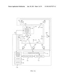 | 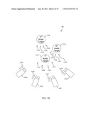 |
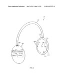 | 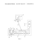 |
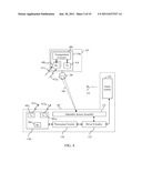 | 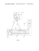 |
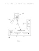 | 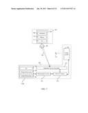 |
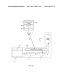 | 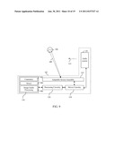 |
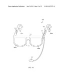 | 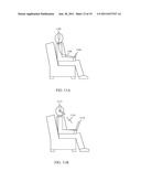 |
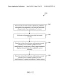 | 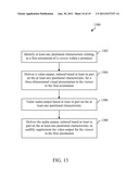 |
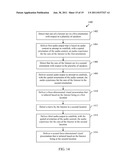 | 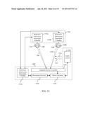 |
 |  |
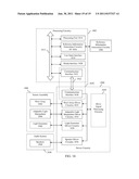 |
| New patent applications in this class: | |
| Date | Title |
|---|---|
| 2019-05-16 | Image display device for displaying composite image |
| 2018-01-25 | System and method for generating 3d image content which enables user interaction |
| 2017-08-17 | Three dimensional content projection |
| 2016-09-01 | Three-dimensional image display apparatus |
| 2016-09-01 | User adaptive 3d video rendering and delivery |
| New patent applications from these inventors: | |
| Date | Title |
|---|---|
| 2021-10-14 | Method and system for a networked self-configuring communication device utilizing user preference information |
| 2017-06-15 | Computing system supporting online purchases |
| 2016-05-19 | Method and system for dynamic routing and/or switching in a network |
| 2016-05-12 | Integrated wireless resonant power charging and communication channel |
| 2016-05-12 | Method and system for processing information based on detected biometric event data |
| Top Inventors for class "Television" | |
| Rank | Inventor's name |
|---|---|
| 1 | Canon Kabushiki Kaisha |
| 2 | Kia Silverbrook |
| 3 | Peter Corcoran |
| 4 | Petronel Bigioi |
| 5 | Eran Steinberg |