Patent application title: CUP STRUCTURE
Inventors:
Ching-Mei Yang (Taichung City, TW)
Assignees:
JACK WORTH CO., LTD.
IPC8 Class: AB65D602FI
USPC Class:
220669
Class name: Receptacles sidewall structure contoured sidewall (e.g., curved, corrugated, ribbed, variable thickness, etc.)
Publication date: 2011-06-30
Patent application number: 20110155747
Abstract:
An improved cup structure includes a cup body having an inner cup and an
outer cup, with a space disposed between the inner cup and the outer cup.
In the cup body, bottoms of the inner and outer cups are connected by an
extension rod having an ornament; one end of the extension rod is adhered
to an outer bottom of the inner cup and placed in the outer cup with the
inner cup. Edges of the inner and outer cup are melted together, and glue
is filled from an aperture at the bottom at the outer cup to secure the
other end of the extension rod and the ornament within the space.Claims:
1. An improved cup structure comprising a cup body having an inner cup
and an outer cup, a space disposed between the inner cup and the outer
cup, the cup structure characterized in that: in the cup body, bottoms of
the inner and outer cups are connected by an extension rod having an
ornament, one end of the extension rod adhered to an outer bottom of the
inner cup and placed in the outer cup with the inner cup, edges of the
inner and outer cup melted together, glue filling from an aperture at the
bottom at the outer cup to secure the other end of the extension rod and
the ornament within the space.
2. The improved cup structure as claimed in claim 1, wherein the inner cup, the outer cup, the extension rod and the ornament of the cup body are all made of a glass material and combined together with a glass glue.
3. The improved cup structure as claimed in claim 1, wherein the inner cup and the outer cup are gradually separated from each other from below a cup opening or a cup neck to form the space between the inner and outer cups.
4. The improved cup structure as claimed in claim 1, wherein the ornament is a decorative object including fish, animals, or cartoon figures.
5. The improved cup structure as claimed in claim 1, wherein the ornament has different colors.
6. The improved cup structure as claimed in claim 1, wherein the inner cup and the outer cup have curved profiles.
Description:
BACKGROUND OF THE INVENTION
[0001] 1. Field of the Invention
[0002] The present invention relates to an improved cup structure, and more particularly to an improved cup structure that provides visual effects.
[0003] 2. Description of the Related Art
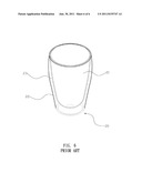
[0004] Currently, typical cup body structures, as shown in FIG. 6, have a cup body 20 that comprises an inner cup 21 and an outer cup 22, and the inner cup 21 and the outer cup 22 are gradually separated below their openings or necks and a space 23 is formed between the inner and outer cups 21, 22. When liquid is poured into the cup body 20, the double layered design provides good thermal isolation properties.
[0005] However, while the prior art structure can provide good thermal isolation properties, its appearance is not interesting or entertaining.
[0006] Therefore, it is desirable to provide an improved cup structure to mitigate and/or obviate the aforementioned problems.
SUMMARY OF THE INVENTION
[0007] An objective of the present invention is to provide an improved cup structure, which can be designed for different occasions or entertainment purposes.
[0008] A cup body has an inner cup and an outer cup, and a space is disposed between the inner cup and the outer cup. In the cup body, bottoms of the inner and outer cups are connected by an extension rod having an ornament, and one end of the extension rod is adhered to an outer bottom surface of the inner cup and placed in the outer cup together with the inner cup. Edges of the inner and outer cups are melted together, and glue (glass glue) is filled-in from an aperture at the bottom at the outer cup to secure the other end of the extension rod and the ornament within the space.
[0009] With the above-mentioned structure, the following benefits can be obtained: 1. The cup body has improved visual effects with the ornament for different occasions or purposes. 2. The ornament is placed between the inner and outer cups and is protected from damage by the outer cup.
[0010] Other objects, advantages, and novel features of the invention will become more apparent from the following detailed description when taken in conjunction with the accompanying drawings.
BRIEF DESCRIPTION OF THE DRAWINGS
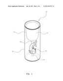
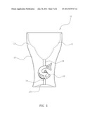
[0011] FIG. 1 is a perspective view of an embodiment of the present invention.
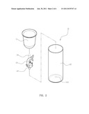
[0012] FIG. 2 is an exploded perspective view of an embodiment of the present invention.
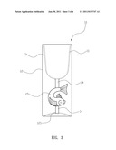
[0013] FIG. 3 is a schematic drawing of an embodiment of the present invention.
[0014] FIG. 4 shows an embodiment ornament according to the present invention.
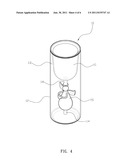
[0015] FIG. 5 shows an embodiment of inner and outer cups having curved profiles according to an embodiment of the present invention.
[0016] FIG. 6 is a schematic drawing of a prior art cup body.
DETAILED DESCRIPTION OF THE PREFERRED EMBODIMENT
[0017] First, please refer to FIGS. 1, 2 and 3. A cup body 10 has an inner cup 11 and an outer cup 12, and a space 13 is disposed between the inner cup 11 and the outer cup 12. In the cup body 10, bottoms of the inner and outer cups 11, 12 are connected by an extension rod 14 having an ornament 15, and one end of the extension rod 14 is adhered to an outer bottom surface of the inner cup 11 and placed in the outer cup 12 together with the inner cup 11. Edges of the inner and outer cups 11, 12 are melted together, and glue (glass glue) is filled-in from an aperture 121 at the bottom at the outer cup 12 to secure the other end of the extension rod 14 and the ornament 15 within the space 13.
[0018] Accordingly, for actual usage, liquid is poured into the inner cup 11, and the outer cup 12 is able to be held by a user. Since the inner and outer cups 11, 12 are separated by the space 13, if the liquid filling the inner cup 11 has a relatively higher or lower temperature, the space provides thermal isolation to prevent the user from being burned or suffering frostbite. Furthermore, this structure utilizes the ornament 15 to increase the visual effects of the cup body 10.
[0019] Moreover, the ornament 15 in the cup body 10 can be any one of various figures, such as animals, cartoon figures, lucky charms like angels, and have different colors, for more a impressive visual impact. In addition, the inner cup 11 and the outer cup 12 may have curved profiles as shown in FIG. 5, for different design appearances.
[0020] With the above-mentioned structure, the following benefits can be obtained: 1. The cup body 10 has improved visual effects with the ornament 15 for different occasions or purposes. 2. The ornament 15 is placed between the inner and outer cups 11, 12 and is protected from damage by the outer cup 12.
[0021] Although the present invention has been explained in relation to its preferred embodiment, it is to be understood that many other possible modifications and variations can be made without departing from the spirit and scope of the invention as hereinafter claimed.
User Contributions:
Comment about this patent or add new information about this topic:
Images included with this patent application:
 |  |
 |  |
 |  |
| Similar patent applications: | |
| Date | Title |
|---|---|
| 2009-06-11 | Bottom coupling structure for containers |
| 2010-02-18 | Disposable cup which may be used as packing material and manufacturing method of the same |
| 2011-11-10 | Access-hole cover for support structures |
| New patent applications in this class: | |
| Date | Title |
|---|---|
| 2016-06-23 | Deformation-resistant container with panel indentations |
| 2016-06-16 | Drinking vessel with ergonomic rim |
| 2016-05-05 | Formatting container |
| 2016-04-28 | Transport holder for an object to be transported and method for transporting an object to be transported using said type of transport holder |
| 2016-02-11 | Body engaging concave container |
| Top Inventors for class "Receptacles" | |
| Rank | Inventor's name |
|---|---|
| 1 | Daniel Lee Bizzell |
| 2 | Frank Yang |
| 3 | Terry Vovan |
| 4 | William P. Apps |
| 5 | Lowell L. Wood, Jr. |