Patent application title: CASE FOR COMMUNICATION SIGNAL ACCESS APPARATUS
Inventors:
Yung-Chi Cheng (Bade City, TW)
Ching-Feng Hsieh (Taipei City, TW)
Assignees:
ASKEY COMPUTER CORP.
IPC8 Class: AB65D4314FI
USPC Class:
206320
Class name: Special receptacle or package for a household appliance
Publication date: 2011-06-23
Patent application number: 20110147246
Abstract:
A case for communication signal access apparatus comprises a box, a
cover, and a hinge portion. The opening surrounding the box is configured
with a first leaning part, and the opening surrounding the box is
configured with a second leaning part, and the edge surrounding the
second leaning part is configured with side dike. The hinge portion is
configured on the inner surface on one side of the box and on the inner
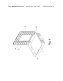
surface on one side of the cover. When the cover is closed and sealed
with the box, the side dike seals the seam from the closing of the first
leaning part with the second leaning part. Thus, the case for
communication signal access apparatus according to the present invention
employs the side dike to separate water or dust from introducing into the
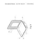
case through the seam between the first leaning part and the second
leaning part.Claims:
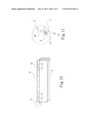
1. A case for communication signal access apparatus, which comprises a
box, a cover, and a hinge portion joining the box and the cover at one
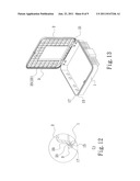
side, corresponding closing locations of the box and the cover being
provided with a first leaning part and a second leaning part
respectively, wherein the improvement comprises: an outer edge of the
second leaning part configured with a side dike for sealing a seam formed
between the first leaning part and the second leaning part.
2. The case for communication signal access apparatus according to claim 1, wherein each of the first leaning part and the second leaning part has a surrounding structure, and the side dike also has a surrounding structure surrounding the outer edge of the second leaning part.
3. The case for communication signal access apparatus according to claim 2, wherein an inner edge of the side dike joined with the second leaning part is configured with a surrounding groove.
4. The case for communication signal access apparatus according to claim 1, wherein an inner surface of the side dike is configured with a waterproof pad.
5. The case for communication signal access apparatus according to claim 4, wherein the waterproof pad has a wedged structure.
6. The case for communication signal access apparatus according to claim 1, wherein the first leaning part and the second leaning part are configured with a waterproof filler therebetween.
7. The case for communication signal access apparatus according to claim 6, wherein the waterproof filler includes a first elastic washer fixed on the first leaning part.
8. The case for communication signal access apparatus according to claim 7, wherein the waterproof filler further includes a second elastic washer fixed on the second leaning part.
9. The case for communication signal access apparatus according to claim 6, wherein the waterproof filler includes a second elastic washer fixed on the second leaning part.
Description:
CROSS-REFERENCE TO RELATED APPLICATIONS
[0001] This non-provisional application claims priority under 35 U.S.C. §119(a) on Patent Application No(s). 098223680 filed in Taiwan, R.O.C. on 17 Dec. 2009, the entire contents of which are hereby incorporated by reference.
FIELD OF THE INVENTION
[0002] The present invention relates to a case for utilizing in communication signal access apparatus, and particularly to a case that can effectively prevent water or dust from penetrating into the case.
BACKGROUND OF THE INVENTION
[0003] In our daily life, the application of various wired communication apparatuses, such as telephone and ADSL, are popular and widely used. Because of the continuous progress in technologies, the data transmission speed for various types of communication apparatus is continuously improved, and the precision requirement in the associated devices is increasingly demanded, and the control of environmental conditions of the apparatuses is becoming more crucial. Except for the heat dissipation problems during operation of the product, the fundamental issue of the communication apparatuses is how to prevent the permeation of water or dust into the internal components of the apparatuses so that those internal components are protected from the humid and dusty environment. The deterioration of internal components can be prevented so that the apparatuses are operated normally, and the lifespan of the internal components is preserved. As for the signal access apparatuses applied for connecting different kinds of communication signal transmission devices, they are mostly installed outdoor, which are inevitably and continuously exposed to wind blowing, sunlight and rain. In other words, the communication apparatuses are continuously subjected to moisture, windy and dusty conditions. Thus, the design of the cover structure of the communication apparatuses is important for protecting the internal components as the cover has to be both waterproof and dustproof.
[0004] FIG. 1 to FIG. 3 are schematic views including the side sectional view after assembling a apparatus with a cover and the enlarged view of A portion of the conventional communication signal access apparatus of FIG. 2 respectively. As shown in the figures, the case of the conventional communication signal access apparatus comprises: a box 10, a cover 20, and an elastic washer 30, wherein the box 10 is configured for accommodating various related signal transmission devices, and the periphery of the box 10 provides a plurality of signal access holes 103 and a locking portion 102, in which the periphery of the opening of the box 10 is surrounded with a flange 104, and the outer periphery of the flange 104 is configured with a first leaning part 105 outwardly protruded. The top surface of the first leaning part 105 is configured into a first surrounding slot 106. The cover 20 is hinged with one side of the box 10 with at least one hinge portion 201 for covering with the outer periphery of the flange 104 beside the opening of the box 10, and the portion of the cover 20 corresponding to the locking portion 102 is configured with a lock head 202 for locking the box 10 with the cover 20. The periphery of the cover 20 is surrounded with a second leaning part 203 as shown in FIG. 3, which is a schematic view enlarged from the A portion of FIG. 2. The bottom surface of the second leaning part 203 of FIG. 3 is configured with a second surrounding slot 204, which is corresponding to the first surrounding slot 106 of the box 10. The first surrounding slot 106 and the second surrounding slot 204 may oppositely accommodate and sandwich the elastic washer 30.
[0005] During the operation, the signal access holes 103 are used for connecting the external signal wiring into the box 10 to connect to various signal transmission devices. The space between various signal wiring and signal access holes 103 will be appropriately filled and sealed with suitable materials in order to prevent water and dust from penetrating into the box 10 through the gaps or holes. The cover 20 employs the hinge portion 201 to pivot to the cover 20 so that the cover 20 is used to close the opening of the box 10. The cover 20 utilizes the lock head 202 and the locking portion 102 to be locked with the box 10. At this time, the second surrounding slot 204 of the cover 20 will be fitted with the first surrounding slot 106 of the box 10 to be pressed on the elastic washer 30, so that the elastic washer 30 will have an elastic deformation and is used to fill the joint portion between the box 10 and the cover 20 for sealing purpose, and the basic waterproof and dustproof effect. However, the conventional structure has the following defects in practical application:
[0006] 1. there is a manufacturing tolerance existed during manufacturing process of the box 10 and the cover 20, and there is an assembly tolerance existed when the hinge portion 201 is hinged with the box 10 and the cover 20, the accumulation of these tolerances easily result a gap after assembling of the box 10 with the cover 20, as a result, the water or dust can permeate through the gap into the case.
[0007] 2. the gap portion between the box 10 and the cover 20 is exposed externally, the rain and sand can be easily permeated into the joint gap and gradually penetrated into the case.
[0008] 3. the box 10 and the cover 20 are distorted and deformed by the pressing force when the box 10 and the cover 20 are compressed together, the elastic washer 30 is mostly made of rubber material with bad deformation property, as a result, the elastic washer 30 usually cannot be used to accommodate effectively the box 10 and the cover 20 once it has been deformed. Therefore, a substantial gap is formed and provides an opportunity for the permeation of rain and dust.
[0009] 4. During assembly process, the elastic washer 30 has to be installed into the first surrounding slot 106 of the box 10 or in the second surrounding slot 204 of the cover 20, as a result, the assembly process of the conventional structure is complex and difficult. Since the elastic washer 30 cannot be assembled easily, it is easily to be disintegrated or detached during operation and can result a significant problem during the assembling process.
[0010] Therefore, the main object of the present invention is to provide a case for communication signal access apparatus that can effectively prevent water or dust from penetrating into the case.
SUMMARY OF THE INVENTION
[0011] In view of the defects in the prior art, one object of the present invention is to provide a case for communication signal access apparatus, which employs the side dike to form the first protection structure preventing water or dust from introducing into the case.
[0012] Another object of the present invention is to provide a case for communication signal access apparatus, which employs the first elastic washer, the second elastic washer, or the first elastic washer and the second elastic washer to form the second protection structure preventing water or dust from introducing into the case.
[0013] Further another object of the present invention is to provide a case for communication signal access apparatus, which is adhered to the first elastic washer and the second elastic washer onto the first leaning part and the second leaning part, so that the first elastic washer and the second elastic washer are easily configured and will not be detached easily.
[0014] To this end, the case for communication signal access apparatus according to the present invention comprises a box, a cover, and a hinge portion joining the box and the cover on the same side, and the opposite closing locations for the box and the cover are respectively provided with a first leaning part and a second leaning part, which is characterized in: the outer edge of the second leaning part is configured with the side dike for sealing the seam with opposite closing of the first leaning part and the second leaning part.
[0015] Thus, the case for communication signal access apparatus according to the present invention can effectively prevent water or dust from introducing into the case.
BRIEF DESCRIPTION OF DRAWINGS
[0016] FIG. 1 is a 3-D view of the case for a conventional communication signal access apparatus;
[0017] FIG. 2 is a side sectional view of the case for a conventional communication signal access apparatus after sealing;
[0018] FIG. 3 is a schematic enlarged view of A1 of FIG. 2;
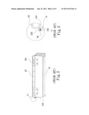
[0019] FIG. 4 is a 3-D view of a preferred embodiment according to the present invention;
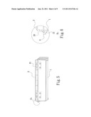
[0020] FIG. 5 is a side sectional view of a preferred embodiment according to the present invention after sealing;
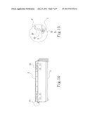
[0021] FIG. 6 is a schematic enlarged view of B1 of FIG. 5;
[0022] FIG. 7 is a schematic enlarged view of B2 of FIG. 5 in accordance with another preferred embodiment of the present invention;
[0023] FIG. 8 is a schematic enlarged view of B3 of FIG. 5 in accordance with another preferred embodiment of the present invention;
[0024] FIG. 9 is a 3-D view of further another preferred embodiment according to the present invention;
[0025] FIG. 10 is a side sectional view of further another preferred embodiment according to the present invention after sealing;
[0026] FIG. 11 is a schematic enlarged view of C1 of FIG. 10;
[0027] FIG. 12 is a schematic enlarged view of C2 of further another preferred embodiment according to the present invention;
[0028] FIG. 13 is a 3-D view of further another preferred embodiment according to the present invention;
[0029] FIG. 14 is a side sectional view of further another preferred embodiment according to the present invention; and
[0030] FIG. 15 is a schematic enlarged view of D1 of FIG. 14.
DETAILED DESCRIPTION OF PREFERRED EMBODIMENTS
[0031] To fully understand the objects, features and effects of the present invention, the present invention is described in details with the following embodiments in connection with the attached figures as follows:
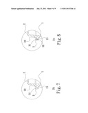
[0032] FIG. 4 and FIG. 6 are respectively the 3-D view, the side sectional view after closing and the schematic enlarged view of the B1 of FIG. 5 in accordance with a preferred embodiment of the present invention. As shown in the figures, the case for communication signal access apparatus comprises a box 1, a cover 2 and one hinge portion 21, wherein the opposite closing locations for the box 1 and the cover 2 are respectively provided with a first leaning part 15 and a second leaning part 23. The first leaning part 15 is formed integrally with the box 1, or, after manufacturing, to be joined with the opening of the box 1. FIG. 6 shows a schematic enlarged view of the B1 of FIG. 5, wherein the second leaning part 23 is formed integrally with the cover 2, or, after manufacturing, the opening of the cover 2 is surrounded with the second leaning part 23. The outer edge surrounding the second leaning part 23 is vertically configured with a side dike 3. The side dike 3 is formed integrally with the second leaning part 23, or, after manufacturing, to be vertically joined with the outer edge of the second leaning part 23. One side of each hinge portion 21 is secured on one of the inner surfaces of the box 1, and the other side of the hinge portion 21 is secured on one of the inner surfaces of the cover 2. When the box 1 is closed with the cover 2 by pivoting of the hinge portions 21, the second leaning part 23 of the cover 2 will be closed with the first leaning part 15 of the box 1, and the side dike 3 will seal the seam between the first leaning part 15 and the second leaning part 23. Thus, the side dike 3 can form the first protection structure, so that the inlet of the seam between the first leaning part 15 and the second leaning part 23 is turned in the direction to prevent water or dust from penetrating into the case directly through the seam between the first leaning part 15 and the second leaning part 23.
[0033] From B1 of FIG. 6, the first leaning part 15 and the second leaning part 23 are configured in a surrounding structure outside the opening of the box 1 and the cover 2, and the side dike 3 is also in a surrounding structure surrounding an outer edge of the second leaning part 23.
[0034] FIG. 7 shows an enlarged view of B2 in accordance with another preferred embodiment of the present invention. As shown in FIG. 7, the inner edge of the side dike 3 joining with the second leaning part 23 may be configured with a surrounding groove 31. When the cover 2 is closed with the box 1, the upper side of an outer edge of the first leaning part 15 may be against the inner edge of the side dike 3 joining with the second leaning part 23, so that the cover 2 cannot firmly be closed with the box 1, and easily causing the seam. Thus, the design of the surrounding groove 31 may accommodate the upper side of the outer edge of the first leaning part 15 for preventing forming seam between the cover 2 and the box 1.
[0035] FIG. 8 is a schematic enlarged view of B3 in accordance with another preferred embodiment of the present invention. As shown in FIG. 8, the inner surface of the side dike 3 is configured with a waterproof pad 32 to seal the gap between the side dike 3 and the first leaning part 15 caused by manufacturing tolerance.
[0036] The waterproof pad 32 is in a wedge-like structure so that when the cover is closed with the box, the upper side of the outer edge of the first leaning part 15 is easily introduced for enhancing the convenience during closing.
[0037] FIG. 9 to FIG. 11 are the 3-D view, the side sectional view after closing and the schematic enlarged view of C1 in accordance with another preferred embodiment of the present invention. As shown in the figures, the first leaning part 15 and the second leaning part 23 are configured with a waterproof filler therebetween, and the waterproof filler includes a first elastic washer 17 fixed on the first leaning part 15; the first elastic washer 17 is adhered to the first leaning part 15 by an adhesive material, thereby allowing simple installation of the first elastic washer 17 and preventing it from falling off. When the cover 2 is closed with the box 1, the second leaning part 23 will be closed with the first elastic washer 17 on the first leaning part 15, which will generate partial deformation to make the first elastic washer 17 firmly filling the gap between the cover 2 and the box 1 after closing. The side dike 3 can form as a barrier outside the first elastic washer 17. Thus, the first elastic washer 17 can form a second protection structure. Although the water or dust might be introduced between the side dike 3 and the first leaning part 15, the first elastic washer 17 can also block them introducing into the case.
[0038] FIG. 12 is a schematic enlarged view of C2 in accordance with another preferred embodiment of the present invention. As shown in FIG. 12, the waterproof filler may further include a second elastic washer 25 fixed on the second leaning part 23. The second elastic washer 25 may be adhered to the second leaning part 23 with the back adhesive, so the configuration is simple and not easy for falling off. When the cover 2 is closed with the box 1, the second elastic washer 25 on the second leaning part 23 will be closed with the first elastic washer 17 on the first leaning part 15, which will generate partial deformation to make the first elastic washer 17 and the second elastic washer 25 firmly filling the gap between the cover 2 and the box 1 after closing. The side dike 3 can form as a barrier outside the seam between the first elastic washer 17 and the second elastic washer 25. Thus, the first elastic washer 17 and the second elastic washer 25 can form a second protection structure. Although the water or dust might be introduced between the side dike 3 and the first leaning part 15, the first elastic washer 17 and the second elastic washer 25 can also block them introducing into the case.
[0039] FIG. 13 to FIG. 15 are the 3-D view, the side sectional view after closing, and the schematic enlarged view of D1 in accordance with another preferred embodiment of the present invention. As shown in the figures, the waterproof filler may include a second elastic washer 25 fixed on the second leaning part 23. The second elastic washer 25 may be adhered to the second leaning part 23 with the back adhesive, so the configuration is simple and not easy for falling off. When the cover 2 is closed with the box 1, the second elastic washer 25 on the second leaning part 23 may be closed with the first leaning part 15, which will generate partial deformation to make the second elastic washer 25 firmly filling the gap between the cover 2 and the box 1 after closing. The side dike 3 can form as a barrier outside the second elastic washer 25. Thus, the second elastic washer 25 can form a second protection structure. Although the water or dust might be introduced between the side dike 3 and the first leaning part 15, the second elastic washer 25 can also block them introducing into the case.
[0040] The material for the first elastic washer 17 and the second elastic washer 25 may be EPDM (Ethylene Propylene Diene Monomer), which provides larger deformation to firmly fill the gap between the cover 2 and the box 1 after closing, or fill the gap between the cover 2 and the box 1 after slight deformation, so as to greatly enhance the waterproof or dustproof effect.
[0041] The present invention has been disclosed in the context with preferred embodiments. However, the skilled in the art should appreciate that these embodiments are only used to describe the present invention, but not a limitation on the scope of the present invention. It should be noted that all the equivalent variances and replacement on the embodiments should be within the scope of the present invention. Thus, the claimed scope of the present invention should be defined by the attached claims.
User Contributions:
Comment about this patent or add new information about this topic:
| People who visited this patent also read: | |
| Patent application number | Title |
|---|---|
| 20140251023 | CHEWING MONITORING DEVICE |
| 20140251022 | BURST PRESSURE MONITORING DEVICE EMPLOYED IN A PRESSURE TRANSMITTER |
| 20140251021 | SYSTEM AND METHOD FOR MULTIPLEXED AND BUFFERED MINIATURIZED SENSOR ARRAYS |
| 20140251020 | METHOD AND APPARATUS FOR PIPE PRESSURE MEASUREMENTS |
| 20140251019 | COPLANAR PROCESS FLUID PRESSURE SENSOR MODULE |
Images included with this patent application:
 |  |
 |  |
 |  |
 |  |
 |
| New patent applications in this class: | |
| Date | Title |
|---|---|
| 2016-06-16 | Protective cases |
| 2016-05-19 | Encasement |
| 2016-01-21 | Packing box for electric home appliance |
| 2015-11-26 | Tub insert system for top loading washer |
| 2015-10-29 | Case for remote control units |
| New patent applications from these inventors: | |
| Date | Title |
|---|---|
| 2013-10-31 | Electromagnetic shielding cover and device having the same |
| 2013-10-24 | Electromagnetic shielding cover |
| 2013-10-24 | Sliding door structure |
| 2013-10-10 | Smallcell base station and channel assignment method for the same |
| 2013-10-10 | Ultrasonic welding structure and ultrasonic welding method |
| Top Inventors for class "Special receptacle or package" | |
| Rank | Inventor's name |
|---|---|
| 1 | Donald E. Weder |
| 2 | Brett R. Glass |
| 3 | Daniel Lee Bizzell |
| 4 | Andrea Biondi |
| 5 | Nicole E. Glass |