Patent application title: RADIO CHANNEL MODEL FOR ICI CANCELLATION IN MULTI-CARRIER SYSTEMS
Inventors:
Xiabo Zhang (Shanghai, CN)
Ni Ma (Shanghai, CN)
Assignees:
NXP B.V.
IPC8 Class: AH04L2700FI
USPC Class:
375259
Class name: Pulse or digital communications systems using alternating or pulsating current
Publication date: 2011-06-09
Patent application number: 20110135018
Abstract:
A channel modeling method for Inter Carrier Interference (ICI)
cancellation in multi-carrier wireless communication systems comprises:
describing the channel with a plurality of fixed matrices and an
equal-numbered plurality of unfixed variables; one-to-one pairing each of
the described plurality of unfixed variables with one of described
plurality of fixed matrices. Corresponding system is also provided. The
method and system can compensate for the channel distortion of the
Doppler Effect even if the Doppler Frequency Offset is relatively
significant.Claims:
1. A method for a channel model for a multi-carrier wireless
communication system, comprising: describing the channel to include a
plurality of fixed matrices and an equal-numbered plurality of unfixed
variables; and one-to-one pairing of each of the described plurality of
unfixed variables with one of the described plurality of fixed matrices.
2. The method of claim 1, further comprising dividing the unfixed variables and fixed matrices into L groups such that every group includes T unfixed variables paired with T fixed matrices, wherein, L is the maximum multi-path number and T can vary from one to an infinite integer.
3. The method of claim 2, further comprising describing the channel features of one path with one divided group.
4. The method of claim 3, further comprising defining the fixed matrices of the described one divided group as a progressional spread of ICI description.
5. The method of claim 4, further comprising: defining the multi-carrier wireless system is an orthogonal frequency division multiplexing (OFDM) system; dividing the Doppler Spectrum spread range into a plurality of segments each small enough such that the corresponding channel response can be treated as an impulse function in the frequency domain, and such for each segment, the received signal is: y ( n ) = l = 0 L h ( l ) exp ( j Δ fn ) s ( n - l ) + w ( n ) ##EQU00019## where Δf is the unitary frequency offset for the segmentation, h(l) is the time domain channel parameters within one OFDM symbol.
6. The method of claim 5, further comprising; after performing an FFT operation at the receiver side, the received frequency domain signal is: Y = l = 0 L h ( l ) [ E l X + CE l X ] Equation A ##EQU00020## where Y = [ Y 0 Y 1 Y N - 1 ] ##EQU00021## is the received signals in the frequency domain, X = [ X 0 X 1 X N - 1 ] ##EQU00022## is the transmitted signals in the frequency domain, E l [ exp ( - j2.pi. l 0 / N ) 0 0 0 exp ( - j2.pi. l 1 / N ) 0 0 0 exp ( - j2.pi. l ( N - 1 ) / N ) ] ##EQU00023## is the phase rotation matrix resulting from propagation delay and C = [ 0 c 1 c 2 c N - 1 c - 1 0 c 1 c N - 2 c - 2 c - 1 0 c N - 3 c - ( N - 1 ) c - ( N - 2 ) c - ( N - 3 ) 0 ] ##EQU00024## is the matrix representing ICI, in which cs is described in the following equation c s ≈ t = 0 T f t ( Δ f ) ctg t ( π s / N ) ( ctg ( π s / N ) - j ) Equation B ##EQU00025## the described one divided group defines the channel according to the following Equation C: Y = l = 0 L ( h 0 ( l ) E l X + t = 1 T h t ( l ) C t E l X ) ##EQU00026## wherein, ht(l) is the unfixed variables including the channel impulse response and Doppler frequency offset for a corresponding segment, C t = [ 0 c 1 t c 2 t c N - 1 t c - 1 t 0 c 1 t c N - 2 t c - 2 t c - 1 t 0 c N - 3 t c - ( N - 1 ) t c - ( N - 2 ) t c - ( N - 1 ) t 0 ] , ##EQU00027## cst=ctgt(πs/N)(ctg(πs/N)-j), the matrices CtEl(0.ltoreq.t≦T) of the one path are the progressional spread of ICI, and t is the progressional rank.
7. The method of claim 5, further comprising making T larger so that Equation C provides a more accurate determination of ICI.
8. The method of claim 6, further comprising estimating the variables ht(l) using a linear estimation algorithm.
9. The method of claim 7, further comprising if the variables of one OFDM symbol include (L+1)(T+1) pilot signals or more, then the linear estimation algorithm is the following: Let the data have a zero value to construct: X=[P00 . . . 0P10 . . . 0 . . . P.sub.(L+1)(T+1)-1]T, where Ps is pilot signal, [ ]T is the transpose operator and the corresponding received signals are: Y=[y00 . . . 0y10 . . . 0 . . . y.sub.(L+1)(T+1)-1]T [ ]T is the transpose operator; by substituting X and Y into Equation C then (L+1)(T+1) equations are achieved and the ht(l) variables are determined by solving this set of simultaneous linear equations, which result in low processing delay and achievable performance, especially under high SNR condition.
10. The method of claim 4, wherein the multi-carrier system is selected from the group consisting of OFDM, SC-FDMA, MC-CDMA.
11. A system for a channel model of a multi-carrier wireless communication system having a maximum multi-path number of L and that includes a plurality of User Equipment (UEs), comprising: a Pilot Assignment Model for pilot allocation by high layers of L groups of pilots to each UE of said plurality of UEs a channel model that includes a plurality of fixed matrices and an equal-numbered plurality of unfixed variables paired one-to-one such that each of the plurality of unfixed variables is paired with a different one of the plurality of fixed matrices.
12. The system of claim 11, wherein the unfixed variables and fixed matrices are divided into L groups such that every group includes T unfixed variables paired with T fixed matrices, wherein, T can vary from one to an infinite integer.
13. The system of claim 12, wherein channel features of one path are described by one divided group.
14. The system of claim 13, wherein the fixed matrices of the one divided group form a progressional spread of ICI description.
15. The system of claim 14, wherein: the multi-carrier wireless system is an orthogonal frequency division multiplexing (OFDM) system; a Doppler Spectrum spread range is divided into a plurality of segments each small enough such that the corresponding channel response can be treated as an impulse function in the frequency domain, and such for each segment, the received signal is: y ( n ) = l = 0 L h ( l ) exp ( jΔ fn ) s ( n - l ) + w ( n ) ##EQU00028## where Δf is the unitary frequency offset for the segmentation and h(l) is the time domain channel parameters within one OFDM symbol
16. The method of claim 15, further comprising; after performing an FFT operation at the receiver side, the received frequency domain signal is: Y = l = 0 L h ( l ) [ E l X + CE l X ] Equation A ##EQU00029## where Y = [ Y 0 Y 1 Y N - 1 ] ##EQU00030## is the received signals in the frequency domain, X = [ X 0 X 1 X N - 1 ] ##EQU00031## is the transmitted signals in the frequency domain, E l [ exp ( - j2.pi. l 0 / N ) 0 0 0 exp ( - j2.pi. l 1 / N ) 0 0 0 exp ( - j2.pi. l ( N - 1 ) / N ) ] ##EQU00032## is the phase rotation matrix resulting from propagation delay and C = [ 0 c 1 c 2 c N - 1 c - 1 0 c 1 c N - 2 c - 2 c - 1 0 c N - 3 c - ( N - 1 ) c - ( N - 2 ) c - ( N - 3 ) 0 ] ##EQU00033## is the matrix representing ICI, in which cs is described in the following equation c s ≈ t = 0 T f t ( Δ f ) ctg t ( π s / N ) ( ctg ( π s / N ) - j ) Equation B ##EQU00034## the described one divided group defines the channel according to the following Equation C: Y = l = 0 L ( h 0 ( l ) E l X + t = 1 T h t ( l ) C t E l X ) Equation C ##EQU00035## wherein, ht(l) is the unfixed variables including the channel impulse response and Doppler frequency offset for a corresponding segment, C t = [ 0 c 1 t c 2 t c N - 1 t c - 1 t 0 c 1 t c N - 2 t c - 2 t c - 1 t 0 c N - 3 t c - ( N - 1 ) t c - ( N - 2 ) t c - ( N - 1 ) t 0 ] , ##EQU00036## cst=ctgt(πs/N)(ctg(πs/N)-j), the matrices CtEl(0.ltoreq.t≦T) of the one path are the progressional spread of ICI, and t is the progressional rank.
17. The system of claim 16, wherein T is made larger in order that Equation C provides a more accurate determination of ICI.
18. The system of claim 17, wherein the receiver further comprises a linear estimation module that estimates the variables ht(l) using a linear estimation algorithm.
19. The system of claim 18, wherein if the variables of one OFDM symbol include (L+1)(T+1) pilot signals or more, then the linear estimation algorithm is the following: let the data have a zero value to construct: X=[P00 . . . 0P10 . . . 0 . . . P.sub.(L+1)(T+1)-1]T, where Ps is pilot signal, [ ]T is the transpose operator and the corresponding received signals are: Y=[y00 . . . 0y10 . . . 0 . . . y.sub.(L+1)(T+1)-1]T [ ]T is the transpose operator; by substituting X and Y into Equation C then (L+1)(T+1) equations are achieved and the ht(l) variables are determined by solving this set of simultaneous linear equations, which result in low processing delay and achievable performance, especially under high SNR condition.
20. The system of claim 11, wherein the multi-carrier system is selected from the group consisting of OFDM, SC-FDMA, MC-CDMA.
Description:
[0001] The present invention relates generally to communication systems
and more particularly to a novel radio channel model for Inter Carrier
Interference (ICI) cancellation in multi-carrier systems.
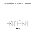
[0002] In multi-carrier systems, a symbol duration is increased by splitting the high-rate serial data stream into many low-rate parallel streams. As illustrated in FIG. 1, in orthogonal frequency division multiplexing (OFDM), for example, a stream of signals are modulated on many equally spaced parallel subcarriers. Modulation and demodulation are implemented by means of Inverse Fast Fourier Transform (IFFT) 101 and its inverse (FFT) 102, respectively. The orthogonality of the signals, when transmitted over a radio channel, can only be maintained if the channel is flat and time-invariant. For time-varying channels self-interference occurs, among others, among signals at different subcarriers and is called Inter Carrier Interference (ICI). Some proposed solutions for ICI mitigation require a modification to the transmit format and are thus not suitable for existing standards. Others without this requirement cannot be used due to high speed of the user devices, e.g., when used in a vehicle, train or plane at their normal cruising speeds, while still others are too complex for a typical mobile user electronic device.
[0003] As shown in FIG. 1 an OFDM system is an example of a multi-carrier system in which the frequency domain signals are transformed into a time domain by an IFFT module 101:
s ( n ) = 1 N k = 0 N - 1 d k j2π nk / N ( - ( N - 1 ) ≦ n ≦ N - 1 ) Equation 1 ##EQU00001##
The received signal y(n) can be expressed as:
y ( n ) = l = 0 L h ( n , l ) s ( n - l ) + w ( n ) Equation 2 ##EQU00002##
Replacing s(n) with Equation 1, Equation 2 can be rewritten as:
y ( n ) = 1 N k = 0 N - 1 d k H k ( n ) j2π nk / N + w ( n ) Equation 3 ##EQU00003##
where
H k ( n ) = l = 0 L h ( n , l ) - j2π lk / N ##EQU00004##
and L is the maximum multipath number. The kth sub-carrier output from the FFT module 102 can be expressed as
Y k = 1 N k = 0 N - 1 y ( n ) - j 2 π nk / N = d k H k + α k + w k where Equation 4 H k = 1 N n = 0 N - 1 H k ( n ) Equation 5 α k = 1 N m = 0 , m ≠ k N - 1 d m n = 0 N - 1 H m ( n ) exp [ j2π n ( m - k ) / N ] Equation 6 w k = 1 N n = 0 N - 1 w ( n ) - j2 π nk / N Equation 7 ##EQU00005##
The dkHk is the expected received signal and the αk represents Inter-Carrier Interference (ICI) caused by the time-varying nature of the channel. wk is white Gaussian noise. Thus, ICI is structured according to the transmit standard.
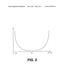
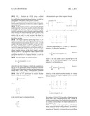
[0004] The ICI is a significant problem for multi-carrier systems, especially in a high mobility environment. As an inherent interference within OFDM-based systems, ICI results from incomplete orthogonality of the sub-carriers, which is caused by several factors, e.g., carrier frequency offset between transmitter and receiver, Doppler Effect, etc. The mobile radio channel brings the spectrum spread to the received signals. When a pure sinusoidal tone of frequency fc is transmitted, the received signal spectrum, called as Doppler spectrum, will have components in the range fc-fm to fc+fm, which is shown in FIG. 2.
[0005] Considering one sub-carrier on the receiving side, the data on one sub-carrier is interfered with by the data on other sub-carriers, as described by the following Equations 8 and 9
d l ' = c 0 d i + l = 0 - N l ≠ i c l - i d i Equation 8 ##EQU00006##
where di is transmitted data, dl' is the corresponding received data, cl-i is the ICI coefficient representing the ICI power level from the lth sub-carrier on the sub-carrier:
c l - i = 1 N sin π ( l - i + Δ fT ) sin π ( l - i + Δ FT N ) × exp j π ( N - 1 ) ( l - i + Δ fT ) N Equation 9 ##EQU00007##
[0006] A major reason that past proposed ICI cancellation schemes have not solved the ICI problem is the lack of a suitable channel model for addressing the ICI problem in multi-carrier wireless communication systems.
[0007] Other features and advantages of the present invention will become apparent from the following detailed description, taken in conjunction with the accompanying drawings, illustrating by way of example the principles of the present invention.
[0008] FIG. 1 illustrates a conventional OFDM system model;
[0009] FIG. 2 illustrates the spectrum shape of a Doppler spread;
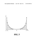
[0010] FIG. 3 illustrates segmentation of the Doppler spectrum spread; and
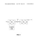
[0011] FIG. 4 illustrates an OFDM system modified according to the present invention to include a linear estimation module that estimates the channel features, according to an exemplary embodiment of the present invention.
[0012] A detailed description of the iterative channel estimation method and system to which this method is applied, are now provided.
[0013] In the present invention a more accurate channel model is provided. This is a new model in which the basic idea is modelling the frequency domain channel features (ICI included) as having two parts: a first part comprising multiple fixed matrices and a part comprising unfixed variables. The unfixed variables are estimated via the pilots. The more fixed matrices that are used, the more accurately the channel is estimated. Moreover, the unfixed variables can be estimated by a linear algorithm.
[0014] The Doppler spectrum spread (range from fc-fm to fc+fm) is divided into many small segments during which the channel impulse response remains almost the same. For each segment, the channel model in Equation 9 serves as a baseline. First, channel impulse response is described for every segment by employing fixed matrices and unfixed variables to approximate Equation 9. By combining all segments, the channel impulse response on the whole Doppler spectrum spread is achieved. If the segmented Doppler spread is small enough, the corresponding channel response can be treated as an impulse function in the frequency domain, as shown in FIG. 3.
[0015] For each segment, the received signal is:
y ( n ) = l = 0 L h ( l ) exp ( j Δ fn ) s ( n - l ) + w ( n ) ##EQU00008##
where Δf is the unitary frequency offset for the segmentation, and h(l) is the time domain channel parameters within one OFDM symbol. The unfixed variables and fixed matrices are divided into L groups, where L is the maximum multipath number and every group includes T variables/matrices.
[0016] After the FFT operation at the receiver side, the received frequency domain signal is:
Y = l = 0 L h ( l ) [ E l X + CE l X ] Equation 10 ##EQU00009##
where
Y = [ Y 0 Y 1 Y N - 1 ] ##EQU00010##
is the received signals in frequency domain,
X = [ X 0 X 1 X N - 1 ] ##EQU00011##
is the transmitted signals in the frequency domain,
E l = [ exp ( - j 2 π l 0 / N ) 0 0 0 exp ( - j 2 π l 1 / N ) 0 0 0 exp ( - j2π l ( N - 1 ) / N ) ] ##EQU00012##
is the phase rotation matrix resulting from propagation delay and
C = [ 0 c 1 c 2 c N - 1 c - 1 0 c 1 c N - 2 c - 2 c - 1 0 c N - 3 c - ( N - 1 ) c - ( N - 2 ) c - ( N - 3 ) 0 ] ##EQU00013##
is the matrix representing ICI, in which cs is described in Equation 9. As derived in Appendix A,
c s ≈ t = 0 T f t ( Δ f ) ctg ' ( π s / N ) ( ctg ( πs / N ) - j ) Equation 11 ##EQU00014##
where T is the rank number used to describe the ICI. The bigger T is, the more accurate Equation 11 is. Therefore, Equation 11 can be rewritten as:
Y = l = 0 L ( h 0 ( l ) E l X + t = 1 T h l ( l ) C t E l X ) Equation 12 ##EQU00015##
where ht(l) is the unfixed variables including the channel impulse response and Doppler frequency offset for a corresponding segment,
C t = [ 0 c 1 t c 2 t c N - 1 t c - 1 t 0 c 1 t c N - 2 t c - 2 t c - 1 t 0 c N - 3 t c - ( N - 1 ) t c - ( N - 2 ) t c - ( N - 1 ) 1 0 ] , and ##EQU00016## c s t = ctg ' ( π s / N ) ( ctg ( πs / N ) - j ) . ##EQU00016.2##
The matrices CtEl(0≦t≦T) of one path are the progressional spread of ICI, and t is the progressional rank. Usually the variables corresponding to lower rank matrices are larger than the variables corresponding to the higher rank matrices, i.e., ht1(l)>ht2(l)(t1<t2).
[0017] Combining all the segmentations of the Doppler spread, a practical channel model is achieved. The matrices Ct and El are fixed and only the ht(l)'s are altered along with segmentations. Therefore, the format of the proposed channel model on the whole Doppler spread is the same as Equation 12, the only difference lies in ht(l).
[0018] In order to use Equation 12 to describe the channel features, a total of (L+1)(T+1) variables of (ht(l)) have to be estimated. A basic linear estimation algorithm is provided as an example only of how to obtain the variables ht(l), since other algorithms providing the same result can be used. This linear estimation algorithm can be used to estimate the variables if one OFDM symbol includes (L+1)(T+1) pilots signals (or more). The example of a basic linear estimation scheme is described below.
[0019] Let the transmitted data have a zero value to construct:
X=[P00 . . . 0P10 . . . 0 . . . P.sub.(L+1)(T+1)-1]T,
where Ps is a pilot signal and [ . . . ]T is the matrix transposition operator. Correspondingly, the received Pilot signals in the frequency domain are:
Y=[y00 . . . 0y10 . . . 0 . . . y.sub.(L+1)(T+1)-1]T
Substituting X and Y into Equation 12 results in a system of (L+1)(T+1) linear equations. Then the variables are derived by solving this set of linear equations, which means low processing delay and achievable performance, especially under high SNR condition.
[0020] The present invention provides the above new channel model comprising multiple fixed matrices and unfixed variables, as shown in Equation 12 which describes the channel response, where a total of (L+1)(T+1) variables (ht(l)) are estimated.
[0021] Referring now to FIG. 4, an exemplary embodiment of an OFDM system according to the present invention is illustrated in which the receiver comprises means to implement a channel estimation scheme that is diagrammatically shown by the block E 501. In the present invention an OFDM system transmit blocks of N symbols where the shape and size of the block processed on reception is free, in order to best match block size to the system architecture. Further, the OFDM system assigns L groups of pilots for each UE where L is the maximum multi-path delay, according to the distributed pilot allocation scheme of the present invention. Maximum rank number T is the number of variables/matrices included in each group.
[0022] The purpose of the invention is to provide a radio channel model suitable for ICI estimation and cancellation in multi-carrier systems. FIG. 4 illustrates an exemplary embodiment of an OFDM system modified in accordance with the present invention. In order to perform the linear estimation algorithm to obtain the channel variables, the data parts of transmitted signals X are set to zero so that only pilot signals Xp are sent by the transmission side to the receiver side of the system and are received thereby as Yp.
[0023] The channel estimation is conducted in module LE 401. The pilot format and position is assigned according to the UE mobility, and then the pilots are inserted into OFDM symbol before IFFT module PAM 402.
[0024] The pilots are assigned to UEs by high layers Pilot Assignment Module 402 and the receiver side demodulates received pilot-only signals using the Fast Fourier Transform 102. Then, according to an exemplary embodiment, a linear estimation module LE 401 can be used to solve a system of (L+1)(T+1) equations, assuming that one OFDM symbol includes (L+1)(T+1) pilots signals (or more)). The example of a basic linear estimation scheme is described below.
[0025] Let the transmitted data have a zero value to construct:
X=[P00 . . . 0P10 . . . 0 . . . P.sub.(L+1)(T+1)-1]T,
where Ps is a pilot signal and [ . . . ]T is the matrix transposition operator. Correspondingly, the received Pilot signals in the frequency domain are:
Y=[y00 . . . 0y10 . . . 0 . . . y.sub.(L+1)(T+1)-1]T
Substituting X and Y into Equation 12 results in a system of (L+1)(T+1) linear equations. Then the variables to describe the channel features, a total of (L+1)(T+1) variables of (ht(l)) are derived by solving this set of linear equations, which means low processing delay and achievable performance, especially under high SNR condition. Module LE 401 solves these linear equations and outputs (ht(l)).
[0026] While exemplary embodiments of the present invention have been provided, one skilled in the art will realize that the invention is not limited to the specific details and exemplary embodiments shown and described herein. Accordingly, various modifications may be made thereto without departing from the spirit or scope of the general inventive concept as defined by the appended claims and their equivalents.
APPENDIX A
[0027] c s = 1 N ( 1 - j tg Δ fT π N ) sin πΔ fT exp ( - jπ s / N ) exp ( jπ Δ fT ) sin ( sπ / N ) + cos ( s π / N ) tg Δ fT π N = F ( Δ fT , N ) 1 - j tg ( s π / N ) tg ( s π / N ) + tg Δ fT π N = F ( Δ fT , N ) ctg ( s π / N ) - j 1 + tg Δ fT π N ctg ( s π / N ) ctg Δ fT π N ctg ( s π / N ) 1 = F ( Δ fT , N ) ( t = 0 ∞ ( - 1 ) t tg t Δ fT π N ctg t ( s π / N ) ) ( ctg ( s π / N ) - j ) = t = 0 ∞ f t ( Δ fT , N ) ctg t ( s π / N ) ( ctg ( s π / N ) - j ) ##EQU00017##
where F (ΔfT,N) is a function of ΔfT and N:
f t ( Δ fT , N ) = 1 N ( 1 - j tg Δ fT π N ) sin πΔ fT exp ( j πΔ fT ) ( - 1 ) t tg t Δ fT π N ##EQU00018##
User Contributions:
Comment about this patent or add new information about this topic:
| People who visited this patent also read: | |
| Patent application number | Title |
|---|---|
| 20120247789 | A FLUID COMPOSITION FOR USE IN INFLATABLE BAG PLUGGING OF AN EARTH BORE HOLE |
| 20120247788 | SEAL WITH BELLOWS STYLE NOSE RING |
| 20120247787 | Injector Head For Coiled Tubing Systems |
| 20120247786 | REMOTELY OPERATED SINGLE JOINT ELEVATOR |
| 20120247785 | HYDRAULICALLY OPERATED WELLBORE LIQUID LIFT USING CASING GAS AS ENERGY SOURCE |
Images included with this patent application:
 |  |
 |  |
 |  |
| New patent applications in this class: | |
| Date | Title |
|---|---|
| 2018-01-25 | Simultaneous wireless information and power transmission method, and transmission apparatus and reception apparatus using the same |
| 2018-01-25 | Receiving device and method using single rf chain |
| 2017-08-17 | Variable time offset in a single frequency network transmission system |
| 2016-06-23 | Apparatus and method for distributing content from an hd radio system |
| 2016-06-09 | Methods and apparatus for scrambling symbols over multi-lane serial interfaces |
| New patent applications from these inventors: | |
| Date | Title |
|---|---|
| 2017-05-18 | Method for measuring downlink channel quality, transmit end, receive end, and system |
| 2016-06-09 | Communication method and apparatus |
| 2015-10-29 | Master-slave base station cluster, central unit, remote unit, and information processing method |
| 2015-10-29 | User equipment and method for estimating an inter cell interference |
| 2015-07-30 | Method of communication with distributed antenna array system and array system |
| Top Inventors for class "Pulse or digital communications" | |
| Rank | Inventor's name |
|---|---|
| 1 | Marta Karczewicz |
| 2 | Takeshi Chujoh |
| 3 | Shinichiro Koto |
| 4 | Yoshihiro Kikuchi |
| 5 | Takahiro Nishi |