Patent application title: Method of Controlling a Combustion Facility Using a Combination of Coefficient of Resistance and Flame Front Estimation
Inventors:
Soeren Nymann Thomsen (Virum, DK)
Benny Elbaek Soerensen (Aarre, DK)
IPC8 Class: AF23N100FI
USPC Class:
431 12
Class name: Combustion process of combustion or burner operation controlling or proportioning feed
Publication date: 2011-05-26
Patent application number: 20110123939
Abstract:
The present invention relates to a method of controlling at least one
parameter (1,2) of a combustion facility, said combustion facility
comprising an in-feed system feeding fuel to a number of moving grates on
which the fuel is fed forward and subjected to successive drying,
ignition, combustion and outburning, primary air for the combustion being
supplied from beneath the grates and through the layer of fuel on the
grates, said method comprising -calculating a coefficient of resistance
(ζpv) for the air flow through the grates and fuel, -controlling the
at least one parameter (1,2) of the combustion facility based on the
coefficient of resistance (ζpv), and -providing an estimation of the
position (Fpv) of the flame front by image analysis of a camera image of
the combustion zone and -using said estimated position (Fpv) of the flame
front to provide a correction of the control of the at least one
parameter (1,2) based on the coefficient of resistance (ζpv).Claims:
1. Method of controlling at least one parameter (1, 2) of a combustion
facility, said combustion facility comprising an in-feed system feeding
fuel to a number of moving grates on which the fuel is fed forward and
subjected to successive drying, ignition, combustion and outburning,
primary air for the combustion being supplied from beneath the grates and
through the layer of fuel on the grates, said method comprising
calculating a coefficient of resistance (ζpv) for the air flow
through the grates and fuel, controlling the at least one parameter (1,
2) of the combustion facility based on the coefficient of resistance
(ζpv), and providing an estimation (Fpv) of the position of the
flame front by image analysis of a camera image of the combustion zone
and using said estimated position (Fpv) of the flame front to provide a
correction of the control of the at least one parameter (1, 2) based on
the coefficient of resistance (ζpv).
2. Method in accordance with claim 1, wherein the at least one parameter comprises the speed (1) of the in-feed system.
3. Method in accordance with claim 1 or 2, wherein the at least one parameter comprises the speed (2) of at least one of the moving grates.
4. Method in accordance with any of the preceding claims, wherein the correction to the control based on the coefficient of resistance (ζpv) is performed by a feedforward introduction of the estimated position (Fpv) of the flame front (FIG. 1).
5. Method in accordance with any of the preceding claims, wherein the correction to the control based on the coefficient of resistance (ζpv) is performed by a scaling introduction of the estimated position (Fpv) of the flame front (FIG. 2).
6. Method in accordance with any of the preceding claims, wherein the correction to the control based on the coefficient of resistance (ζpv) is performed by a gain scaling introduction of the estimated position (Fpv) of the flame front (FIG. 3).
Description:
TECHNICAL FIELD
[0001] The present invention relates to a control method used in a combustion facility comprising a feed-in system, feeding fuel to a number of moving grates, on which the fuel is fed forward and subjected to successive drying, ignition, combustion and outburning, primary air for the combustion being supplied from beneath the grates and through the layer of fuel on the grates.
BACKGROUND ART
[0002] In combustion facilities of this kind it is known to provide a control of the in-feed system and possibly the speed of the moving grates, based on a calculation of the coefficient of resistance, e.g. based on Bernoulli's principle, for the airflow through the grates and fuel. A method of this kind is known from EP 955 499.
DISCLOSURE OF THE INVENTION
[0003] It is the object of the present invention to provide a method of the kind referred to above, with which it is possible to provide a more precise control of the combustion, and this object is achieved with a method of said kind, which according to the present invention provides a correction of the control based on the coefficient of resistance by using an estimated position of the flame front, which is provided by image analysis of a camera image of the combustion zone. With this arrangement, the set point to or the control signal of the coefficient of resistance controller can be corrected, whenever the position of the flame front is detected to be deviating from the optimal position thereof.
BRIEF DESCRIPTION OF THE DRAWINGS
[0004] In the following detailed part of the present description, the invention will be explained in more detail with reference to the exemplary embodiment of a method according to the invention shown in the drawings, in which
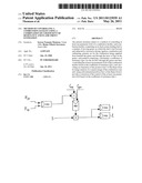
[0005] FIG. 1 schematically indicates a configuration of the feeding control system where the set point of the coefficient of resistance controller is additively corrected (feed forward) by the flame front control signal,
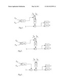
[0006] FIG. 2 schematically indicates a configuration of the feeding control system where the set point of the coefficient of resistance controller is scaled (scaling) by the flame front control signal, and
[0007] FIG. 3 schematically indicates a configuration of the feeding control system where the flame front control signal directly scales (gain scaling) the set point to the feeding control system.
DESCRIPTION OF THE PREFERRED EMBODIMENTS
[0008] The control systems shown in FIGS. 1-3 comprise a controller for each of two parameters of a combustion facility, namely the speed 1 of feeding combustible fuel into the combustion chamber and the speed 2 of conveyance on a successive first combustion grate, respectively. Each of the two controllers is indicated to be PID-controllers and these are primarily controlled in accordance with a set point 3 for the grate speed, which is based on the wanted steam/energy production for the plant. Correction of the grate speed set point 3 for the two controllers is performed by means of the coefficient of resistance ζ over the combustion zone. The coefficient of resistance ζ is calculated for the combustion zone, e.g. using measurement of pressure on opposite sides of the combined combustion grate and layer of combustible material thereon, airflow, pressure, and temperature of the combustion air, etc. The calculation of the coefficient of resistance ζ may be based on several different equations, such as
Δ p = 1 2 ζ ρ v x ⇄ ζ = 2 Δ p ρ v x ##EQU00001##
where [0009] Δp=Pressure loss over the grate and fuel thereon [0010] ζ=Coefficient of resistance [0011] ρ=Density of the media (combustion air) [0012] v=Velocity of the media [0013] x=Exponent dependent on flow being laminar or turbulent, or
[0013] ζ I = R T P Δ p V ##EQU00002##
where [0014] ζI=Coefficient of resistance [0015] R=Gas constant for air (=287.1 J/(kgK)) [0016] T=Temperature of air (K) [0017] P=Pressure of air (Pa) [0018] Δp=Pressure loss over the grate and fuel thereon [0019] V =Volume flow of air (m3/s)
[0020] Or any other relevant equation giving a coefficient of resistance ζpv related to the thickness and density of the fuel on the grates.
[0021] The coefficient of resistance ζpv over the combustion zone thus calculated provides a good indication of necessary corrections of the speed 1,2 of the feeding system, due to the fact that the coefficient of resistance ζpv provides a good estimation of the thickness of the waste layer in the combustion zone.
[0022] In accordance with the present invention, however, the set point ζsp of the coefficient of resistance may be too high or too low and needs to be corrected further. This need for correction is in accordance with the present invention provided by use of the estimated position Fpv of the flame front, said estimate being provided by image analysis of a camera image of the combustion zone. The camera is, in a preferred embodiment, a red-green-blue image camera, however, other types of cameras may be used, such as an infrared camera.
[0023] In the exemplary embodiment shown in FIG. 1, the flame front controller is provided with a set point Fsp for the flame front and an estimated value Fpv for the flame front position, which is provided to a PID-controller and the output from said PID-controller for the flame front is added to the set point ζsp for the coefficient of resistance controller in order to correct this control value and in the end correct the control of the in-feed speed 1 of combustible fuel into the combustion chamber and the speed 2 of conveyance on the successive first combustion grate.
[0024] Correspondingly FIG. 2 shows the corresponding system, in which, however, the output from the flame front controller is multiplied by the set point asp for the coefficient of resistance controller.
[0025] Furthermore, FIG. 3 shows an alternative configuration in which the output signal from the flame front controller is multiplied onto the grate speed set point 3 in the same way as the coefficient of resistance controller output signal is multiplied on the result thereof, before being supplied to the PID-controllers for controlling the speed 1 of feeding combustible fuel into the combustion chamber and the speed 2 of conveyance on a successive first combustion grate, respectively.
User Contributions:
Comment about this patent or add new information about this topic:
Images included with this patent application:
 |  |
| New patent applications in this class: | |
| Date | Title |
|---|---|
| 2016-07-14 | Burner assembly and method for combustion of gaseous or liquid fuel |
| 2016-06-30 | Direct-fired heating method and facility for implementing same |
| 2016-06-02 | Combustion system for a boiler |
| 2016-04-28 | Dual fuel burner pressure switch shut off mechanism |
| 2016-03-17 | Combustion apparatus supplying combustion air via suction type fan and method for controlling the same |
| Top Inventors for class "Combustion" | |
| Rank | Inventor's name |
|---|---|
| 1 | Christopher A. Wiklof |
| 2 | Igor A. Krichtafovitch |
| 3 | Joseph Colannino |
| 4 | David Deng |
| 5 | Robert E. Breidenthal |