Patent application title: THERMAL BARRIER COATING WITH A PLASMA SPRAY TOP LAYER
Inventors:
Kevin W. Schlichting (South Glastonbury, CT, US)
Kevin W. Schlichting (South Glastonbury, CT, US)
Michael J. Maloney (Marlborough, CT, US)
David A. Litton (West Hartford, CT, US)
Melvin Freling (West Hartford, CT, US)
John G. Smeggil (Simsbury, CT, US)
John G. Smeggil (Simsbury, CT, US)
David Snow (Glastonbury, CT, US)
Assignees:
UNITED TECHNOLOGIES CORPORATION
IPC8 Class: AC23C412FI
USPC Class:
427454
Class name: Spray coating utilizing flame or plasma heat (e.g., flame spraying, etc.) metal oxide containing coating superposed diverse or multilayer similar coatings applied
Publication date: 2011-04-14
Patent application number: 20110086179
Inventors list |
Agents list |
Assignees list |
List by place |
Classification tree browser |
Top 100 Inventors |
Top 100 Agents |
Top 100 Assignees |
Usenet FAQ Index |
Documents |
Other FAQs |
Patent application title: THERMAL BARRIER COATING WITH A PLASMA SPRAY TOP LAYER
Inventors:
Melvin Freling
Michael J. Maloney
John G. Smeggil
David A. Litton
Kevin W. Schlichting
David Snow
Agents:
Assignees:
Origin: ,
IPC8 Class: AC23C412FI
USPC Class:
Publication date: 04/14/2011
Patent application number: 20110086179
Abstract:
A turbine engine component has a substrate, a thermal barrier coating
deposited onto the substrate, and a sealing layer of ceramic material on
an outer surface of the thermal barrier coating for limiting molten sand
penetration.Claims:
1-14. (canceled)
15. A method for forming a coating on a turbine engine component comprising the steps of: forming a thermal barrier coating on a surface of said turbine engine component; and plasma spraying a sealing layer onto said thermal barrier coating.
16. The method of claim 15, wherein said plasma spraying step comprises plasma spraying a ceramic material onto said thermal barrier coating.
17. The method of claim 15, wherein said plasma spraying step comprises plasma spraying a yttria stabilized zirconia layer onto said thermal barrier coating.
18. The method of claim 15, wherein said plasma spraying step comprises depositing said sealing layer using a plasma spray gun operating at from 30 to 70 volts and from 300 to 900 amps and a ceramic powder flow rate of from 30 to 70 grams per minute.
19. The method of claim 15, wherein said thermal barrier coating step comprises depositing at least one layer of yttria stabilized zirconia onto said surface.
20. The method of claim 15, wherein said thermal barrier coating step comprises depositing at least one layer of gadolinia stabilized zirconia onto said surface.
21. The method of claim 15, wherein said thermal barrier coating step comprises depositing a ceramic material at a temperature of from 1700 to 2000.degree. F., a pressure of from 0.05 to 2.0 millitors, and a feed rate of from 0.3 to 2.0 inches per hour.
22. The method of claim 15, further comprising applying a bond coat to said surface of said turbine engine component prior to said thermal barrier coating forming step.
23. The method according to claim 22, wherein said bond coat applying step comprises applying a material selected from the group of a MCrAlY coating, an aluminide coating, a platinum aluminide coating, a ceramic based material, and a silica based material.
24-33. (canceled)
Description:
BACKGROUND
[0001] (1) Field of the Invention
[0002] The present invention relates to the use of a plasma sprayed outer layer on top of a thermal barrier coating to block the penetration of molten sands into the thermal barrier coating.
[0003] (2) Prior Art
[0004] Turbine engine airfoils used in desert environments may degrade due to sand related distress of thermal barrier coatings. The mechanism for such distress is believed to be caused by the penetration of fluid sand deposits into 7YSZ ceramic thermal barrier coatings that leads to spallation and then accelerated oxidation of exposed metal. It has been observed that gadolinia stabilized zirconia coatings react with fluid sand deposits and a reaction product forms that inhibits fluid sand penetration into the coating. The reaction product has been identified as being a silicate oxyapatite/garnet containing primarily gadolinia, calcia, zirconia, and silica.
[0005] There remains a need however for a coating system which effectively deals with sand related distress.
SUMMARY OF THE INVENTION
[0006] A turbine engine component is provided which uses an air plasma sprayed outer layer on top of a thermal barrier coating to block the penetration of molten sands into the thermal barrier coating.
[0007] In accordance with the present invention, there is provided a turbine engine component which broadly comprises a substrate, a thermal barrier coating deposited onto the substrate, and means for sealing an outer surface of the thermal barrier coating and thereby limiting molten sand penetration into the thermal barrier coating.
[0008] Further in accordance with the present invention, there is provided a method for forming a coating on a turbine engine component broadly comprising the steps of forming a thermal barrier coating on a surface of the turbine engine component, and plasma spraying a sealing layer onto the thermal barrier coating.
[0009] Other details of the thermal barrier coating with a plasma-spray top layer of the present invention, as well as other objects and advantages attendant thereto, are set forth in the following detailed description and the accompanying drawings wherein like reference numerals depict like elements.
BRIEF DESCRIPTION OF THE DRAWINGS
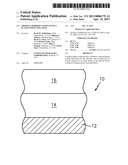
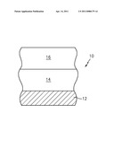
[0010] The FIGURE is a schematic representation of a thermal barrier coating system in accordance with the present invention.
DETAILED DESCRIPTION OF THE PREFERRED EMBODIMENT(S)
[0011] Referring now to the FIGURE, there is shown a turbine engine component 10, such as a blade, a vane, a combustor panel, or a seal having a substrate 12, such as an airfoil portion or a platform portion of a blade or vane or a portion of a combustor panel or a portion of a seal, and a thermal barrier coating 14 on at least one surface of the substrate 12. The substrate 12 may be formed from any suitable material known in the art such as a nickel based superalloy, a cobalt based superalloy, molybdenum, or niobium. Alternatively, the substrate 12 may be a ceramic based substrate or a ceramic matrix composite substrate.
[0012] The thermal barrier coating 14 may comprise one or more layers of a ceramic material such as a yttria stabilized zirconia material or a gadolinia stabilized zirconia material. The yttria stabilized zirconia material may contain from 1.0 to 25 wt % yttria and the balance zirconia. The gadolinia stabilized zirconia material may contain from 5.0 to 99 wt % gadolinia, more preferably 30 to 70 wt %, and the balance zirconia. The ceramic material layer(s) may be deposited using any suitable method known in the art.
[0013] The thermal barrier coating 14 may be applied using any suitable technique known in the art such as electron beam physical vapor deposition, thermal spray, sol-gel, slurry, chemical vapor deposition, and sputtering. The use of different spray parameters will create distinctly different microstructures which would differentiate between the layers, i.e. a dense top sealing layer with a porous bottom layer. A preferred method for depositing the thermal barrier coating is by electron bean physical vapor deposition (EB-PVD). The deposition may occur in a chamber with a temperature of from 1700 to 2000° F. and a pressure of from 0.05 to 2.0 millitors. The ceramic feedstock may be feed at a rate of 0.3 to 2.0 inches per hour with a coating time from 20 to 120 minutes.
[0014] If desired a bond coated may be deposited on the substrate prior to the application of the thermal barrier coating 14. The bond coat may be either a MCrAly coating where M is nickel and/or cobalt, an aluminide coating, a platinum aluminide coating, a ceramic based bond coat, or a silica based bond coat. The bond coat may be applied using any suitable technique known in the art.
[0015] After the thermal barrier coating 14 has been applied to the substrate 12, a plasma-sprayed layer 16 is applied on top of the thermal barrier coating. The plasma-sprayed layer 16 is preferably formed from a ceramic material such as yttria stabilized zirconia. The layer 16 may be formed using a plasma-spray gun operating at from 30 to 70 volts and from 300 to 900 amps. A mixture of argon and helium or argon and hydrogen may be used as the carrier gas. The gun may have a standoff distance from 2 to 8 inches and a ceramic powder flow rate of from 30 to 70 grams per minute. The resulting structure is a two-layer ceramic where the plasma-sprayed layer 16 is preferably on the outer surface. The two layers 14 and 16 may not have a defined interface, but they may rather blend together.
[0016] Plasma-sprayed coatings are formed by injecting powder, either metallic or ceramic, into a plasma plume where the material is heated and accelerated toward the substrate to be coated. The molten or semi-molten particles impact the substrate and form a splat or pancake type structure. The coating thickness is built up as additional molten particles impact the substrate and form splats. As these splats build up, defects are incorporated into the coating such as porosity (both micro and macro), cracks, and splat boundaries. Spray parameters can be adjusted to yield a very dense or porous coating depending on the application. The resulting structure of the outer plasma-sprayed layer acts as a barrier to prevent the penetration of molten sand into the thermal barrier coating below due to its lower porosity and more tortuous path. The average porosity for the EB-PVD coating layer 14 can be anywhere from 10 to 20%, while the porosity of the plasma-sprayed coating layer 16 can be from 2.0 to 30% depending on the parameters used.
[0017] The benefit of the present invention is a thermal barrier coating system that resists penetration of molten silicate material and provides enhanced durability in environments where sand induced distress of turbine airfoils occurs. The outer plasma sprayed layer seals the surface of the thermal barrier coating to limit molten sand from penetrating therein.
[0018] It is apparent that there has been provided in accordance with the present invention a thermal barrier coating with a plasma-spray top layer which fully satisfies the objects, means, and advantages set forth hereinbefore. While the present invention has been described in the context of specific embodiments thereof, other unforseeable alternatives, modifications and variations may become apparent to those skilled in the art having read the foregoing description. Accordingly, it is intended to embrace those alternatives, modifications, and variations as fall within the broad scope of the appended claims.
User Contributions:
comments("1"); ?> comment_form("1"); ?>Inventors list |
Agents list |
Assignees list |
List by place |
Classification tree browser |
Top 100 Inventors |
Top 100 Agents |
Top 100 Assignees |
Usenet FAQ Index |
Documents |
Other FAQs |
User Contributions:
Comment about this patent or add new information about this topic:
| People who visited this patent also read: | |
| Patent application number | Title |
|---|---|
| 20140111867 | LIGHT COMBINING SYSTEM |
| 20140111866 | OPTICAL ASSEMBLY AND LASER ALIGNMENT APPARATUS |
| 20140111865 | OPTICAL DEVICE, IMAGE DISPLAY APPARATUS, AND METHOD FOR MANUFACTURING OPTICAL DEVICE |
| 20140111864 | HELMET MOUNTED DISPLAY SYSTEM ADJUSTABLE FOR BRIGHT AMBIENT LIGHT CONDITIONS |
| 20140111863 | ENHANCED PRISM FILM |
Images included with this patent application:
 |  |
| New patent applications from these inventors: | |
| Date | Title |
|---|---|
| 2021-10-21 | Thermal barrier coating for gas turbine engine components |
| 2017-06-22 | Article having multi-layered coating |
| 2017-06-22 | Method for joining dissimilar engine components |
| 2016-11-17 | Physical vapor deposition using rotational speed selected with respect to deposition rate |
| Top Inventors for class "Coating processes" | |
| Rank | Inventor's name |
|---|---|
| 1 | Xinjian Lei |
| 2 | Shou-Shan Fan |
| 3 | Shunpei Yamazaki |
| 4 | Stephen D. Pacetti |
| 5 | Kai-Li Jiang |