Patent application title: CHEMICAL STORAGE TANK
Inventors:
Chi-Lung Tsai (Kao-Hsiung County, TW)
Assignees:
CHI MEN PRECISION INDUSTRIAL CO., LTD.
IPC8 Class: AB65D632FI
USPC Class:
220612
Class name: End wall structure joint or seam between sidewall and end wall adhered (e.g., welded, cemented, soldered, bonded, etc.)
Publication date: 2011-04-14
Patent application number: 20110084080
Inventors list |
Agents list |
Assignees list |
List by place |
Classification tree browser |
Top 100 Inventors |
Top 100 Agents |
Top 100 Assignees |
Usenet FAQ Index |
Documents |
Other FAQs |
Patent application title: CHEMICAL STORAGE TANK
Inventors:
CHI-LUNG TSAI
Agents:
Assignees:
Origin: ,
IPC8 Class: AB65D632FI
USPC Class:
Publication date: 04/14/2011
Patent application number: 20110084080
Abstract:
A chemical storage tank includes at least a main body and two sealing
members combined together with each other, integrally made of acid-proof
and alkali-proof materials, with a storage space formed inside it for
storing any chemical material or product, and with a circumferential wall
having its upper and its lower end respectively formed with a connecting
opening. The sealing members are integrally made of the same plastic
material of the main body, respectively combined together with the upper
and the lower connecting opening of the main body by Electronics high
frequency welding or heater welding. Thus, the welding portions between
the main body and the sealing members are located around the
circumferential wall, able to prevent pressure in the tank from damaging
the chemical storage tank to insure safety.Claims:
1. A chemical storage tank comprising: at least a main body integrally
made of acid-proof and alkali-proof plastics and provided with a storage
space formed inside it, a connecting opening formed in two ends of a
circumferential wall of said main body; and at least two sealing members
integrally made of acid-proof and alkali-proof plastics, wherein each of
the sealing members comprises; a circumferential wall having a connecting
opening formed in one of its two ends, said circumferential wall has a
thickness between 10.about.45 mm, said connecting opening combined
together with said connecting opening of said main body by electrics high
frequency welding or heater welding.
2. The chemical storage tank as claimed in claim 1, wherein said main body and said sealing members are made of a same material.
3. The chemical storage tank as claimed in claim 1, wherein each of said sealing members is provided with a linking portion formed with an arc for jointing its circumferential wall and its top portion.
4. The chemical storage tank as claimed in claim 1, wherein each of said sealing members is provided with plural reinforcing ribs positioned spaced apart equidistantly in said top portion.
5. The chemical storage tank as claimed in claim 1, wherein said sealing member is made up by welding plural units together.
Description:
CROSS-REFERENCE TO RELATED APPLICATIONS
[0001] This application is a continuation-in-part of application Ser. No. 12/137,405 filed on Jun. 11, 2008, now pending, the content of witch is hereby incorporated by reference in its entirety.
FIELD OF THE INVENTION
[0002] This invention relates to a chemical storage tank, particularly to one consisting of a main body and two sealing members integrally made of acid-proof and alkali-proof plastic materials respectively, leaving no weak portions possibly attacked by the pressure of the chemicals stored in it after having the main body welded together with the sealing members, ensuring the chemicals securely stored in it.
BACKGROUND OF THE INVENTION
[0003] US Patent Application Publication No. 2008/0067179A1, entitled "WATER TANK AND METHOD FOR MANUFACTURING A WATER TANK", describes in the "DESCRIPTION OF THE PREFERED EMBODUMENT" section, paragraph [0048] that: A centering member 31 having the shape of a double cone is inserted into the insertion socket 25 which are aligned with each other. The centering member 31 seats with axial clearance a land in the cavity as defined by both recesses 24. The inner and outer fitting surfaces 16, 17 and also the rib ends 18, in some case, may abut on each other. The sealing means 28 is inserted into the sealing channels 26. The sealing means may be a unitary sealing or, as shown, may be combined from two sealing strips 33 which have mirror image cross-sections. The flange 22 of each opening edge structure R is formed with an outwardly protruding prolonging flange 32 at which the clamping skewbacks 23 are formed. The quick connectors 29 are C-shaped clamps which are pushed over the clamping skewbacks 23 and which hold the sealing 33 compressed. The widths of the inner and outer fitting surfaces 16, 17 in relation to the thickness x of the tank part wall 30 and the outer sealing channel wall 34 already have been explained for to FIG. 7.
[0004] Apparently, in foresaid US Patent Application Publication No. 2008/0067179A1, the sealing means 28 are necessary to be filled in the sealing channels 26 of the inner and the outer fitting surfaces 16, 17 of the two members 1 located at the water tank so that the two members 1 of the water tank can be combined and welded together. Different from foresaid structure, the main body and the sealing members of this invention can be firmly combined together, needless to use the sealing means 28.
[0005] US Patent Application Publication No. 2006/0169704A1, entitled "DOUBLE-WALL CONTAINER FOR CRYOGENIC LIQUID", describes in the "DETAIL DESCRIPTION" section, that: "In FIG. 1 and FIG. 2, . . . . The inner container 1 comprises a central part 5 and end parts 6, 7. These parts 5, 6, 7 are assembled from fiber-reinforced elements or are themselves such elements . . . ;" (Paragraph [0023]) "In the same manner, the outer container 2 comprises a central part 15 which is adjoined on both sides by the end parts 16, 17. . . . ;" (Paragraph [0025]) and "The finished inner container 1 with the collars 11, 12, which are used as the support, is fitted in the outer container 2, which is not yet completely assembled, by said inner container being pushed into the central part 15 of the outer container 2, which part is optionally already connected to one of the two end parts 16, 17, and then the two end parts 16, 17 of the outer container 2 or only the other end part is/are connected to the central part of the outer container. The centering slugs 8, 9 prove useful again here. Only then is the outer container wrapped up with the filament 20. The vessel is then essentially finished." (Paragraph [0026]).
[0006] In foresaid US Patent Application Publication No. 2006/0169704A1, the water tank is composed of the inner container 1 and the outer container 2 secured together by the collars 11, 12 provided therebetween. Different in structure, the water tank of this invention is a single one, and the main body and the sealing member can be firmly combined together, unnecessary to employ the collars 11, 12.
[0007] Another U.S. Pat. No. 2,787,397, entitled "SELF-SEALING PRESSURIZED PLASTICS CONTAINER", includes a character 10 composed of a cap or an upper part and a body or a lower part. The side wall of the cap is constructed to flare outwardly to form a blister as at 16 and then bent inwardly and back upon itself to form an annular recess 17 which terminates in an upturned peripheral rim 18. The cap terminates in a skirt portion 19 extending downwardly from annular rim 18. Only by the annular recess 17, 25 in the annular rim 18, 26 of the blister cap 1626, can the cap or upper part with longitudinal lands 12 at outer sides, and the body or lower part of the character 10 be combined together. Different from foresaid structure, this invention has the main body and the sealing members combined together by high frequency and heat welding.
SUMMARY OF THE INVENTION
[0008] One object of this invention is to offer a chemical storage tank having its main body and its sealing members integrally formed respectively. With two connecting openings of the main body respectively welded with a circumferential wall of the sealing members, welding lines are only positioned at the combining portion of the circumferential wall of the main body and those of the sealing members, able to sufficiently strengthen the structure of the storage tank for securely storing chemicals.
[0009] Another object of this invention is to offer a chemical storage tank having its main body and its sealing members integrally made of acid-proof and alkali-proof plastic material to prevent it from being attacked by chemicals with a high acid value or a high alkaline value. [0010] 1. The chemical storage tank has its main body integrally made of acid-proof and alkali-proof plastic material in any shapes, provided with a storage space for storing chemical material or products. [0011] 2. The circumferential wall of the main body has its upper end and its lower end respectively formed with a connecting opening for being welded together with the sealing members. [0012] 3. The sealing members are integrally made of acid-proof and alkali-proof plastic materials. [0013] 4. Each of the sealing members is provided with a circumferential wall employed to combine with the connecting openings of the circumferential wall of the main body by Electrics high frequency welding or heater welding. [0014] 5. Each of the sealing members is provided with plural reinforcing ribs to strengthen its structure. [0015] 6. The sealing members have a thickness ranging between 10 mm and 45 mm.
BRIEF DESCRIPTION OF DRAWINGS
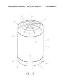
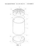
[0016] FIG. 1 is an exploded perspective view of a preferred embodiment of a chemical storage tank in the present invention;
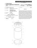
[0017] FIG. 2 is a cross-sectional view of the preferred embodiment of a chemical storage tank in the present invention; and
[0018] FIG. 3 is a perspective view of the preferred embodiment of a chemical storage tank in the present invention.
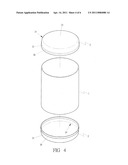
[0019] FIG. 4 is an exploded perspective view of a second preferred embodiment of a chemical storage tank in the present invention;
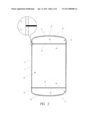
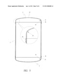
[0020] FIG. 5 is a cross-sectional view of the second preferred embodiment of a chemical storage tank in the present invention; and
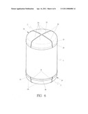
[0021] FIG. 6 is a perspective view of a third preferred embodiment of a chemical storage tank in the present invention.
DESCRIPTION OF THE INVENTION
[0022] As shown in FIGS. 1 and 2, a preferred embodiment of a chemical storage tank in the present invention includes a main body 1 and plural sealing members 2.
[0023] The main body 1 is formed cylindrical, made of acid-proof and alkali-proof plastics. Of course, the main body 1 can be as well shaped annular, elliptic or square. But, an annular one is preferable as it can homogeneously bear a higher pressure. The main body 1 is provided with a storing space 10 formed inside it for disposing chemical material or products, a circumferential wall 11, two connecting openings 12 respectively formed in an upper end and a lower end of the circumferential wall 11.
[0024] The sealing members 2 are integrally made of the same materials of the main body 1 so as to be compatibly welded together with it. The number of the sealing members 2 is equal to that of the connecting openings 12 formed in the upper end and the lower end of the circumferential wall 11 of the main body 1. Each of the sealing members 2 is provided with a circumferential wall 21, said circumferential wall has a thickness between 10˜45 mm, and a connecting opening 22 formed in one end of the circumferential wall 21 for matching with one of the connecting openings 12 of the main body 1 by electric high frequency welding or heater welding. And, as shown in FIGS. 2 and 3, the welding portions between the main body 1 and the sealing members 2 are all located around the circumferential wall of the storage tank, ensuring the whole storage tank to possess sufficient strength against pressure of a chemical stored in it, keeping the storage tank secure in use.
[0025] In addition, as shown in FIGS. 1 and 2 again, each of the sealing members 2 is provided with a linking portion 24 formed with an arc for jointing the circumferential wall 21 and a top portion 23. In stead of a sharp corner designed in the conventional one, the linking portion 24 is strong enough to withstand the pressure of a storing chemical.
[0026] Moreover, as shown in FIGS. 2 and 3, each of the sealing members 2 is also provided with a plurality of reinforcing ribs 25 positioned among the top portion 23 for strengthening the structure of the sealing members 2, so as to enable the storage tank to withstand more pressure, advancing security in service.
[0027] A second preferred embodiment of a chemical storage tank in the present invention, as shown in FIGS. 4 and 5, includes a main body 1 and sealing members 2, which are derived from those described in the first preferred embodiment. The jointing portion 24 of the top portion 23 and the circumferential wall 21 of the sealing member 2 is formed with an arc for preventing pressure in the chemical storage tank from directly attacking the jointing portion 24 to enhance safety of the chemical storage tank. Unlike the first preferred embodiment, the top portion 23 of the sealing member 2 of the second preferred embodiment is provided with no reinforcing ribs 25. For facilitating combination with the main body 1, the top portion 23 of the sealing member 2 is formed with a downward-extending circumferential wall 26 that is covered around a partial circumferential wall of the main body 1, and then the main body and the sealing members 2 are combined together by high frequency welding or heat welding.
[0028] A third preferred embodiment of a chemical storage tank in the present invention, as shown in FIG. 6, includes a main body 1 and a sealing member 2. The main body 1 is the same as that described in the first preferred embodiment, but the sealing member 2 is composed of a plurality of units 2A respectively shaped in advance and then welded together to form the sealing member 2. As shown in FIG. 5, the jointing portion 24 of both the top portion 23 and the circumferential wall 21 of the sealing member 2 are arc-shaped for preventing the jointing portion 24 from being attacked directly by the pressure inside the chemical storage tank, thus able to elevate safety of the chemical storage tank. However, unlike the top portion in the first preferred embodiment, the top portion 23 of the sealing member 2 in the third preferred embodiment is provided with no reinforcing ribs 25. Being closely combined with the main body 1, the top portion 23 of the sealing member 2 is formed with a circumferential wall 26 extending downward and covering a partial circumferential wall of the main body 1, and then the main body 1 and the sealing member 2 are firmly combined together by high frequency welding or heat welding.
[0029] While the preferred embodiment of the invention has been described above, it will be recognized and understood that various modifications may be made therein and the appended claims are intended to cover all such modifications that may fall within the spirit and scope of the invention.
User Contributions:
comments("1"); ?> comment_form("1"); ?>Inventors list |
Agents list |
Assignees list |
List by place |
Classification tree browser |
Top 100 Inventors |
Top 100 Agents |
Top 100 Assignees |
Usenet FAQ Index |
Documents |
Other FAQs |
User Contributions:
Comment about this patent or add new information about this topic:
| People who visited this patent also read: | |
| Patent application number | Title |
|---|---|
| 20220297885 | PALLET APPARATUS |
| 20220297884 | PALLET REASSEMBLY SYSTEM |
| 20220297883 | STACKABLE CONTAINER HAVING HINGED WALLS |
| 20220297882 | FOLDABLE BOX |
| 20220297881 | SLIDER DRAWER TISSUE CARTON |
Images included with this patent application:
 |  |
 |  |
 |  |
 |
| Similar patent applications: | |
| Date | Title |
|---|---|
| 2009-12-17 | Chemical storage tank |
| 2010-04-01 | Detachable bamboo material-based storage container |
| 2009-10-29 | Method and apparatus for abating fugitive emissions from a volatile liquid storage tank |
| 2010-04-01 | Cap assembly with sectional storage chamber for secondary material |
| 2011-12-29 | Method and system for reducing and preventing emissions from liquid storage tanks |
| New patent applications in this class: | |
| Date | Title |
|---|---|
| 2015-04-30 | Fluid reservoir |
| 2015-03-19 | Plastic container for packing of filling product under pressure, and method for the manufacture thereof |
| 2014-12-18 | Disposable container and mixing system comprising the container |
| 2014-07-17 | Three-piece can |
| 2012-11-08 | Attachment systems and methods usable to form enclosures |
| New patent applications from these inventors: | |
| Date | Title |
|---|---|
| 2009-12-17 | Butterfly valve |
| Top Inventors for class "Receptacles" | |
| Rank | Inventor's name |
|---|---|
| 1 | Daniel Lee Bizzell |
| 2 | Frank Yang |
| 3 | Terry Vovan |
| 4 | William P. Apps |
| 5 | Lowell L. Wood, Jr. |