Patent application title: EVAPORATOR FOR LOOP HEAT PIPE SYSTEM
Inventors:
Jung Hyun Yoo (Seoul, KR)
Jee Hoon Choi (Gyeonggi-Do, KR)
Min Whan Seo (Gyeonggi-Do, KR)
IPC8 Class: AF28D1504FI
USPC Class:
16510426
Class name: Liquid fluent heat exchange material utilizing change of state utilizing capillary attraction
Publication date: 2011-03-31
Patent application number: 20110073284
Inventors list |
Agents list |
Assignees list |
List by place |
Classification tree browser |
Top 100 Inventors |
Top 100 Agents |
Top 100 Assignees |
Usenet FAQ Index |
Documents |
Other FAQs |
Patent application title: EVAPORATOR FOR LOOP HEAT PIPE SYSTEM
Inventors:
Jung Hyun YOO
Jee Hoon CHOI
Min Whan SEO
Agents:
Assignees:
Origin: ,
IPC8 Class: AF28D1504FI
USPC Class:
Publication date: 03/31/2011
Patent application number: 20110073284
Abstract:
An evaporator for a loop heat pipe (LHP) system. The evaporator an
evaporator body for accommodating a sintered wick formed by sintering
metal powders, a discharging hole for discharging a working fluid filled
into voids formed between particles of the sintered wick and changed into
a vapor due to being heated, and an inlet hole for introducing the
working fluid changed into a liquid; a first chamber portion coupled to a
side of the inlet hole, and including an inlet for introducing the
working fluid in a liquid phase, and an accommodation space portion for
accommodating the working fluid in a liquid phase; and a capillary
structure that is porous and that is inserted into the accommodating
space portion, wherein the working fluid in a liquid phase introduced
through the inlet is introduced to the evaporator body through the
capillary structure.Claims:
1. An evaporator for a loop heat pipe (LHP) system, the evaporator
comprising:an evaporator body for accommodating a sintered wick formed by
sintering metal powders, a discharging hole for discharging a working
fluid filled into voids formed between particles of the sintered wick and
changed into a vapor due to being heated, and an inlet hole for
introducing the working fluid changed into a liquid;a first chamber
portion coupled to a side of the inlet hole, and comprising an inlet for
introducing the working fluid in a liquid phase, and an accommodation
space portion for accommodating the working fluid in a liquid phase; anda
capillary structure that is porous and that is inserted into the
accommodating space portion,wherein the working fluid in a liquid phase
introduced through the inlet is introduced to the evaporator body through
the capillary structure.
2. The evaporator of claim 1, wherein at least a portion of the capillary structure contacts the sintered wick.
3. The evaporator of claim 1, wherein the capillary structure occupies all portions of the accommodation space portion.
4. The evaporator of claim 1, wherein a capillary pressure of the sintered wick is greater than a capillary pressure of the capillary structure.
5. The evaporator of claim 1, wherein a transmittance of the sintered wick is smaller than a transmittance of the capillary structure.
6. The evaporator of claim 1, further comprising a second chamber portion comprising an outlet coupled to the discharging hole, for discharging the working fluid changed into a vapor, and a vapor accommodation portion for accommodating the working fluid changed into a vapor.
7. The evaporator of claim 1, wherein the sintered wick comprises a space portion, and has a rectangular parallelepiped shape with an open surface, andwherein an outer surface of the sintered wick is coupled to an inner surface of the sintered wick accommodating portion,wherein the open surface is connected to the discharging hole.
8. The evaporator of claim 1, wherein the sintered wick has a rectangular parallelepiped shape,wherein the sintered wick comprises a plurality of vapor paths for guiding the working fluid changed into a vapor, andwherein the plurality of vapor paths are connected to the discharging hole, and each has a circular cross section.
9. The evaporator of claim 7, wherein the sintered wick comprises first sub-sintered wicks that connect top and bottom surfaces of the sintered wick and are spaced apart from each other by a predetermined interval.
10. The evaporator of claim 7, wherein the sintered wick comprises protrusions that protrude from top and bottom surface of the sintered wick and are spaced apart from each other by a predetermined interval.
11. The evaporator of claim 7, wherein the sintered wick comprises: plate-type first sub-sintered wicks that connect top and bottom surfaces of the sintered wick and are spaced apart from each other by a predetermined interval; andsecond sub-sintered wicks of a pin type that protrude from the bottom surface of the sintered wick,wherein the second sub-sintered wicks are disposed between the first sub-sintered wicks and are spaced apart from each other by a predetermined interval.
Description:
CROSS-REFERENCE TO RELATED PATENT APPLICATION
[0001]This application claims the benefit of Korean Patent Application No. 10-2009-0091141, filed on Sep. 25, 2009, in the Korean Intellectual Property Office, the disclosure of which is incorporated herein in its entirety by reference.
BACKGROUND OF THE INVENTION
[0002]1. Field of the Invention
[0003]One or more aspects of the present invention relate to an evaporator for a loop heat pipe (LHP) including a condenser, a vapor transport line, a liquid transport line, and the evaporator, and more particularly, to an evaporator for an LHP system having an improved structure in which bubbles are prevented to from being formed in a working fluid due to heat generated from a heat component when the working fluid in a vapor phase is changed into a liquid while passing through a condenser and then accommodated in a first chamber.
[0004]2. Description of the Related Art
[0005]Electronic parts such as central processing units (CPUs) or semiconductor chips used for various electronic devices such as computers generate a large amount of heat during operation. Such electronic devices are usually designed to operate at room temperature. Accordingly, when heat generated during operation of an electronic device is not effectively removed, performance of the electronic device is severely deteriorated and, in some cases, the electronic device itself may be damaged.
[0006]As a method of removing heat generated by various electronic parts, many approaches have been developed, such as a heat conduction method using a heat sink, a method of using natural convection of air or radiation, a forced convection method using a fan, a method using circulation of a liquid, and a submerged cooling method.
[0007]However, nowadays, as many released electronic products are being made slimmer, an installation distance between electronic parts that generate heat during operation is continuously decreasing and thus heat may not be appropriately removed. Also, since a heat load of electronic parts has continuously increased due to high integration and high performance of the electronic parts, the above-described cooling methods are not able to effectively cool down the electronic parts.
[0008]As a new technology to solve the above problems, a phase change heat transport system that can cool down an electronic part having a high heat load density per unit has been introduced. A thermosyphon system and a cylindrical heat pipe system are examples of the phase change heat transport system.
[0009]According to the thermosyphon system, cooling is achieved using a natural circulation method via a liquid-vapor phase change and a specific gravity difference of a working fluid. As illustrated in FIG. 1, in a conventional cylindrical heat pipe 100, cooling is obtained by circulating the working fluid using a capillary pumping force generated by a sintered wick 102 installed in an interior wall of the pipe 100. When heat is transferred to the working fluid contained in a heat source 101 from a heat source 101, the working fluid is vaporized, and is moved in a direction of an arrow 103 indicating a flow of a vapor. Then, the working fluid is liquefied again while a heat sink 104 takes heat from the working fluid, moves through the sintered wick 102 in a direction of an arrow 105 indicating a flow of a liquid due to a capillary pumping force, and circulates throughout the conventional cylindrical heat pipe 100.
[0010]However, in the thermosyphon system, a condenser section needs to be located higher than an evaporator section. Although this problem is less severe when using a heat pipe of the thermosyphon system, a heat transport ability of the heat pipe is quite deteriorated when a condenser section thereof is located lower with respect to gravity than an evaporator section thereof. Accordingly, since there is a limitation in a positional relationship between the constituent elements in the above two systems, this limitation prevents electronic devices employing the above cooling systems from being made slim.
[0011]Also, since a vapor and a liquid flow in opposite directions in a linear pipe of the thermosyphon system or the cylindrical heat pipe system, the vapor and the liquid may mix together in a middle portion of the pipe. The mixture may make the amount of heat actually transported less than that that can be ideally transported.
[0012]A loop heat pipe (LHP) system has been suggested as an ideal heat transport system that can solve these problems, that is, a positional limitation and mixing between a vapor and a liquid.
[0013]The LHP system is a sort of capillary pumped loop heat pipe (CLP) technology developed by NASA, U.S.A., to remove a large amount of heat generated from communications equipment or electronic equipment used for artificial satellites.
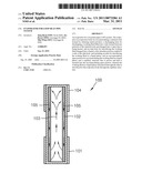
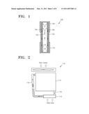
[0014]FIG. 2 is a conceptual view of a conventional LHP system 110. FIG. 3 is a cross-sectional view of an evaporator 114 of the conventional LHP system 110. The conventional LHP system 110 includes a condenser 112, an evaporator 114, a vapor line 116, and a liquid line 118, which form a loop. The vapor line 116 and the liquid line 118 are connected between the condenser 112 and the evaporator 114.
[0015]In addition, the evaporator 114 includes a chamber portion 1144 that accommodates and buffers a liquefied working fluid before the working fluid permeates into a sintered wick 1142 inserted into the evaporator 114. In the conventional LHP system 110, the sintered wick 1142 is installed only in the evaporator 114 unlike in a conventional linear heat pipe (refer to FIG. 1).
[0016]The conventional LHP system 110 operates in the following manner.
[0017]Heat is applied to a contact surface 1148 of the evaporator 114 that contacts a heat source such as a heating component. In this case, at a point of time when the sintered wick 1142 is saturated with the working fluid in a liquid phase, due to the heat applied to the sintered wick 1142, the applied heat vaporizes the working fluid and thus the working fluid changes into a vapor. The vapor is moved towards the condenser 112 along the vapor line 116 connected to a side of the evaporator 114. As the vapor passes through the condenser 112, heat is dissipated externally and thus the vapor is liquefied. The liquefied working fluid is moved towards the evaporator 114 along the liquid line 118 at a side of the condenser 112. The above-described process is repeated so that the heat source can be cooled down. As illustrated in FIG. 3, the sintered wick 1142 is coupled onto an inner surface of the evaporator 114. A space within an inner surface of the sintered wick 1142 functions as a vapor path along which the working fluid changed into a vapor is moved towards the vapor line 116.
[0018]The working fluid liquefied while passing through the condenser 112 moves back to the evaporator 114. In this case, the working fluid is accommodated in the chamber portion 1144 before being absorbed into the sintered wick 1142. The liquefied working fluid stays in the chamber portion 1144 until it is absorbed into the sintered wick 1142 through a through hole 1146 of the chamber portion 1144 due to a capillary pressure of the sintered wick 1142. In addition, the chamber portion 1144 prevents the liquefied working fluid, which is to flow towards the evaporator 114 along the liquid line 118, from flowing backwards along the liquid line 118.
[0019]However, the evaporator 114 of the conventional LHP system 110 makes the conventional LHP system 110 unstable due to the working fluid accommodated in the chamber portion 1144.
[0020]In detail, all of heat generated from heating components needs to be transferred to the evaporator 114 as vaporization energy. However, some sensible heat is transferred to the evaporator 114 through an outer wall of the evaporator 114 and the sintered wick 1142 and thus bubbles are generated in the working fluid accommodated in the chamber portion 1144. These bubbles forms a bubble layer around the liquid line 118 connected to the chamber portion 1144, and acts as a boundary layer that prevents the working fluid from smoothly moving into the chamber portion 1144. Thus, since the working fluid does not smoothly permeate into the sintered wick 1142 of the evaporator 114, the sintered wick 1142 may dry, and the conventional LHP system 110 may not operate any more.
[0021]In addition, the working fluid in the chamber portion 1144 is vaporized and thus may flow backwards along the liquid line 118, or bubbles in the working fluid may flow backwards along the liquid line 118 and collide with an inner surface of the liquid line 118. Thus, since a temperature of each component of the conventional LHP system 110 oscillates, the conventional LHP system 110 may become unstable.
[0022]If, except for the through hole 1146, the chamber portion 1144 is not completely sealed, the working fluid accommodated in the chamber portion 1144 may excessively flow into a space in which the sintered wick 1142 is inserted. That is, if an amount of the working fluid in the space is greater than an ideal amount of the working fluids due to the capillary pressure of the sintered wick 1142, bubbles may be generated in the space by the heat source, and the generated bubbles may prevent the working fluid accommodated in the sintered wick 1142 from being vaporized. Accordingly, an overall temperature of the conventional LHP system 110 may be increased, and the conventional LHP system 110 becomes unstable, thereby reducing the cooling efficiency of the conventional LHP system 110.
SUMMARY OF THE INVENTION
[0023]One or more aspects of the present invention provide evaporators for a loop heat pipe (LHP) system, the evaporators including a porous capillary structure inserted into a chamber portion so that a working fluid in a liquid phase passes through the capillary structure along a liquid line and permeates into a sintered wick, thereby preventing bubbles from being formed so as to increase cooling efficiency of the LHP system.
[0024]According to an aspect of the present invention, there is provided an evaporator for a loop heat pipe (LHP) system, the evaporator including an evaporator body for accommodating a sintered wick formed by sintering metal powders, a discharging hole for discharging a working fluid filled into voids formed between particles of the sintered wick and changed into a vapor due to being heated, and an inlet hole for introducing the working fluid changed into a liquid; a first chamber portion coupled to a side of the inlet hole, and including an inlet for introducing the working fluid in a liquid phase, and an accommodation space portion for accommodating the working fluid in a liquid phase; and a capillary structure that is porous and that is inserted into the accommodating space portion, wherein the working fluid in a liquid phase introduced through the inlet is introduced to the evaporator body through the capillary structure.
[0025]At least a portion of the capillary structure may contact the sintered wick.
[0026]The capillary structure may occupy all portions of the accommodation space portion.
[0027]A capillary pressure of the sintered wick may be greater than a capillary pressure of the capillary structure.
[0028]A transmittance of the sintered wick may be smaller than a transmittance of the capillary structure.
[0029]The evaporator may further include a second chamber portion including an outlet coupled to the discharging hole, for discharging the working fluid changed into a vapor, and a vapor accommodation portion for accommodating the working fluid changed into a vapor.
[0030]The sintered wick may include a space portion, and may have a rectangular parallelepiped shape with an open surface, and an outer surface of the sintered wick may be coupled to an inner surface of the sintered wick accommodating portion, wherein the open surface may be connected to the discharging hole.
[0031]The sintered wick may have a rectangular parallelepiped shape, the sintered wick may include a plurality of vapor paths for guiding the working fluid changed into a vapor, and the plurality of vapor paths may be connected to the discharging hole, and may each have a circular cross section.
[0032]The sintered wick may include first sub-sintered wicks that connect top and bottom surfaces of the sintered wick and are spaced apart from each other by a predetermined interval.
[0033]The sintered wick may include protrusions that protrude from top and bottom surface of the sintered wick and are spaced apart from each other by a predetermined interval.
[0034]The sintered wick may include plate-type first sub-sintered wicks that connect top and bottom surfaces of the sintered wick and are spaced apart from each other by a predetermined interval; and second sub-sintered wicks of a pin type that protrude from the bottom surface of the sintered wick, wherein the second sub-sintered wicks may be disposed between the first sub-sintered wicks and are spaced apart from each other by a predetermined interval.
BRIEF DESCRIPTION OF THE DRAWINGS
[0035]The above and other features and advantages of the present invention will become more apparent by describing in detail exemplary embodiments thereof with reference to the attached drawings in which:
[0036]FIG. 1 is a schematic view for explaining an operation of a conventional cylindrical heat pipe;
[0037]FIG. 2 is a conceptual view of a conventional loop heat pipe (LHP) system;
[0038]FIG. 3 is a cross-sectional view of an evaporator of the conventional LHP system;
[0039]FIG. 4 is a schematic perspective view of an LHP system including an evaporator according to an embodiment of the present invention;
[0040]FIG. 5 is a disassembled perspective view of an evaporator for an LHP system, according to an embodiment of the present invention;
[0041]FIG. 6 is a cross-sectional view of the evaporator taken along a line VI-VI of FIG. 5;
[0042]FIG. 7 is a cross-sectional view of the evaporator taken along a line VII-VII of FIG. 5;
[0043]FIGS. 8 and 9 are cross-sectional views for explaining capillary pressure and transmittance.
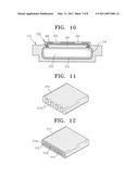
[0044]FIG. 10 is a cross-sectional view of an evaporator for an LHP system, according to another embodiment of the present invention;
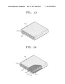
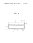
[0045]FIGS. 11 through 14 illustrate a sintered wick of an evaporator for an LHP system, according to various embodiments of the present invention
DETAILED DESCRIPTION OF THE INVENTION
[0046]The present invention will now be described more fully with reference to the accompanying drawings, in which exemplary embodiments of the invention are shown.
[0047]The present invention relates to an evaporator 200 for a loop heat pipe (LHP) system including a condenser 20, a vapor transport line 40, and a liquid transport line 30.
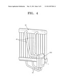
[0048]Referring to FIG. 4, the LHP system includes the evaporator 200, the condenser 20, the vapor transport line 40, and the liquid transport line 30.
[0049]The condenser 20 changes a working fluid received from the evaporator 200 from being in a vapor phase. The condenser 20 takes heat from the working fluid and exhausts the heat to outside air.
[0050]The vapor transport line 40 is a pipe member for connecting the evaporator 200 and the condenser 20 to each other so as to guide the working fluid in a vapor phase due to the evaporator 200 to the condenser 20. The liquid transport line 30 is a pipe member for connecting the condenser 20 and the evaporator 200 to each other so as to guide the working fluid in a liquid phase due to the condenser 20 back to the evaporator 200.
[0051]General operations of the condenser 20, the vapor transport line 40, and the liquid transport line 30 are the same as those described in the Description of the Related Art.
[0052]The present invention is directed to the evaporator 200. The evaporator 200 as well as the condenser 20, the liquid transport line 30, and the vapor transport line 40 is one of components of the LHP system.
[0053]The evaporator 200 for the LHP system will be described in detail with reference to FIGS. 5 through 9.
[0054]FIG. 5 is a disassembled perspective view of the evaporator 200 for the LHP system, according to an embodiment of the present invention. FIG. 6 is a cross-sectional view of the evaporator 200 taken along a line VI-VI of FIG. 5. FIG. 7 is a cross-sectional view of the evaporator 200 taken along a line VII-VII of FIG. 5. FIGS. 8 and 9 are cross-sectional views for explaining capillary pressure and transmittance.
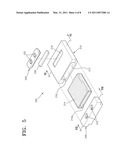
[0055]Referring to FIG. 5, the evaporator 200 includes an evaporator body 210, a first chamber portion 220, and a capillary structure 230.
[0056]The evaporator body 210 contacts a heating component 1 so as to receive heat from the heating component 1. As illustrated in FIG. 4, the heating component 1 contacts an outer surface of the evaporator body 210.
[0057]The evaporator body 210 includes a sintered wick accommodation portion 212 for accommodating a sintered wick 214 formed by sintering metal powders, a discharging hole 218 for discharging the working fluid filled in voids of the sintered wick 214 and changed into a vapor due to being heated, and an inlet hole 216 for introducing the working fluid changed into a liquid.
[0058]The sintered wick accommodation portion 212 is a space for accommodating the sintered wick 214, and has a rectangular parallelepiped shape.
[0059]The discharging hole 218 is formed in the evaporator body 210 so as to discharge the working fluid filled in the voids of the sintered wick 214 and vaporized due to being heated by the heating component 1. According to the present embodiment, an open surface of the sintered wick accommodation portion 212 is the discharging hole 218.
[0060]The inlet hole 216 is formed in the evaporator body 210 so that the working fluid in a vapor phase changed into a liquid by passing through the condenser 20 may flow to the evaporator body 210 along the liquid transport line 30. According to the present embodiment, the inlet hole 216 is formed in a top surface of the evaporator body 210. Of course, a position of the inlet hole 216 may be variously changed. For example, the inlet hole 216 may be formed opposite to the discharging hole 218.
[0061]The sintered wick 214 formed by sintering metal powders is inserted into the sintered wick accommodation portion 212. According to the present embodiment, the sintered wick 214 includes a space formed therein, and has a rectangular parallelepiped shape with an open surface. An outer surface of the sintered wick 214 is coupled to an inner surface of the sintered wick accommodation portion 212. The open surface functions as a vapor path 214a along which the working fluid changed into a vapor flows.
[0062]Numerous voids are formed in the sintered wick 214. The working fluid in a liquid phase permeates into the voids. Generally, the working fluid may be water, acetone, pentane, ammonia, refrigerant (R-134a), or the like.
[0063]The first chamber portion 220 is coupled to a side of the inlet hole 216, and accommodates the working fluid in a liquid phase moved to the evaporator body 210 along the liquid transport line 30. The first chamber portion 220 includes inlets 222, and an accommodation space portion 224.
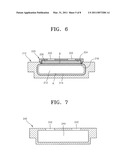
[0064]The inlets 222 are connected to the inlet hole 216 of the evaporator body 210, and are portions for coupling the first chamber portion 220 to the liquid transport line 30. The accommodation space portion 224 accommodates the working fluid in a liquid phase until the working fluid is introduced to the evaporator body 210. As illustrated in FIG. 6, two inlets 222 are formed in a top surface of the first chamber portion 220. The accommodation space portion 224 is formed below the inlets 222. The accommodation space portion 224 includes an open surface that is open downwards.
[0065]The capillary structure 230 is formed of a porous material, and is inserted into the accommodation space portion 224. In this case, the working fluid in a liquid phase introduced through the inlet 222 is introduced to the evaporator body 210 through the capillary structure 230. According to the present embodiment, the capillary structure 230 occupies all portions of the accommodation space portion 224. In addition, a bottom surface of the capillary structure 230 contacts the sintered wick 214 inserted into the evaporator body 210.
[0066]A capillary pressure of the capillary structure 230 is smaller than that of the sintered wick 214, and a transmittance of the capillary structure 230 is greater than that of the sintered wick 214.
[0067]Capillary pressure and transmittance will be described in detail with reference to FIGS. 8 and 9. FIG. 8 is a magnified diagram of a portion "A" of FIG. 6, and is a schematic cross-sectional view of particles constituting the sintered wick 214. FIG. 9 is a magnified diagram of a portion "B" of FIG. 8, and is a schematic cross-sectional view of particles constituting the capillary structure 230.
[0068]A capillary pressure is given by the following equation.
P = 2 σ r ##EQU00001##
[0069]In this equation, `P` is a capillary pressure, `σ` is a surface tension, and `r` is an effective radius of a void formed between particles.
[0070]Since a surface tension of a working fluid is constant, a capillary pressure is determined according to an effective radius of a void formed between particles.
[0071]As illustrated in FIGS. 8 and 9, an effective radius of a void formed between particles 2 constituting the sintered wick 214 is `r1`, and an effective radius of a void formed between particles 3 constituting the capillary structure 230 is `r2`. In this case, since r1<r2, the capillary pressure of the sintered wick 214 is greater than that of the capillary structure 230. In addition, since r1<r2, the working fluid may permeate more easily into the capillary structure 230 than in the sintered wick 214. That is, the transmittance of the capillary structure 230 is greater than that of the sintered wick 214.
[0072]Likewise, when the capillary pressure of the sintered wick 214 is greater than that of the capillary structure 230, and the transmittance of the capillary structure 230 is greater than that of the sintered wick 214, the working fluid in a liquid phase introduced in the first chamber portion 220 may permeate into the sintered wick 214 through the capillary structure 230. If the capillary pressure of the sintered wick 214 is smaller than that of the capillary structure 230, since the working fluid in a liquid phase introduced into the first chamber portion 220 permeates more into the capillary structure 230 than into the sintered wick 214, and thus is not easily moved to the sintered wick 214, the working fluid does not circulate smoothly.
[0073]As illustrated in FIGS. 4 and 5, the evaporator 200 for the LHP system includes a second portion 240.
[0074]The second portion 240 is coupled to a side of the discharging hole 218, and includes an outlet 242, and a vapor accommodation portion 244. The outlet 242 is a portion for discharging the working fluid changed into a vapor, and is coupled to the vapor transport line 40. The vapor accommodation portion 244 accommodates the working fluid in a liquid phase introduced via the vapor path 214a of the sintered wick 214. The vapor accommodation portion 244 prevents a sudden drop in pressure when the working fluid in a vapor phase is moved to the vapor transport line 40. Since a sudden drop in pressure may momentarily increase a moving speed of the working fluid in a vapor phase, which makes the LHP system unstable, the vapor accommodation portion 244 accommodates the working fluid in a vapor phase so as to prevent a sudden drop in pressure in advance.
[0075]Hereinafter, operations and effects of the evaporator 200 for the LHP system will be described in detail.
[0076]Heat generated from the heating component 1 while a surface of the evaporator body 210 is in contact with the heating component 1 is applied to the sintered wick 214 inserted into the evaporator body 210. The working fluid permeated in the sintered wick 214 is changed to a vapor due to the heat applied to the sintered wick 214.
[0077]The working fluid in a vapor phase is moved towards the second portion 240 through the discharging hole 218, is temporally accommodated in the vapor accommodation portion 244 of the second portion 240, and then is moved to the condenser 20 along the vapor transport line 40.
[0078]Heat is taken from the working fluid in a vapor phase and thus the working fluid is changed to a liquid in the condenser 20, and then the working fluid is moved to the first chamber portion 220 along the liquid transport line 30.
[0079]The capillary structure 230 inserted into the accommodation space portion 224 of the first chamber portion 220 absorbs the working fluid in a liquid phase. In addition, the working fluid permeates into the sintered wick 214, which contact the capillary structure 230.
[0080]In this case, since a bottom side of the accommodation space portion 224 is open downwards, and the bottom surface of the capillary structure 230 inserted into the accommodation space portion 224 contacts the outer surface of the sintered wick 214, the working fluid in a liquid phase is absorbed into the capillary structure 230, and then permeates into the voids of the sintered wick 214 due to the capillary pressure of the sintered wick 214.
[0081]The working fluid in a liquid phase permeated into the voids of the sintered wick 214 is heated by heat generated by the heating component 1, and is changed to a vapor. The working fluid in a vapor phase cools down the heating component 1 while circulating through the LHP system.
[0082]Likewise, since the evaporator 200 for the LHP system according to the present embodiment includes the capillary structure 230 inserted into the first chamber portion 220, which has a greater transmittance than the sintered wick 214 and a smaller capillary pressure than the sintered wick 214, the working fluid in a liquid phase introduced through the inlet 222 may be absorbed into the capillary structure 230 in a relatively short time, and the working fluid in a liquid phase absorbed into the capillary structure 230 may permeate into the voids of the sintered wick 214 due to the capillary pressure of the sintered wick 214.
[0083]Thus, bubbles are prevented from being formed in the working fluid in a liquid phase absorbed into the capillary structure 230 of the first chamber portion 220 even though heat generated by the heating component 1 is transmitted to the first chamber portion 220. In addition, since the capillary structure 230 absorbs the working fluid in a liquid phase in a relatively short time, time taken to heat the working fluid using heat generated by the heating component 1 is reduced, thereby preventing bubbles from being formed.
[0084]Even if heat of the heating component 1 is transmitted to the sintered wick 214 or the evaporator body 210, bubbles may be prevented from being formed in the working fluid accommodated in the first chamber portion 220. Thus, the working fluid is prevented from flowing backwards along the liquid transport line 30 due to bubbles. Introduction of the working fluid is not interrupted by a bubble layer formed in the first chamber portion 220. In addition, the sintered wick 214 is prevented from being dried. Thus, the LHP system is maintained more stably than a conventional LHP system.
[0085]In order to prevent the working fluid absorbed into the capillary structure 230 of the first chamber portion 220 from being introduced in a coupling gap between the sintered wick 214 and the evaporator body 210, the sintered wick 214 is formed directly on the evaporator body 210, or the sintered wick 214 and the evaporator body 210 are coupled by using a thermal coupling manner, a metallic bonding manner, or the like, thereby preventing bubbles from being formed between the sintered wick 214 and the evaporator body 210. Thus, since bubbles are prevented from being formed in the coupling gap between the sintered wick 214 and the evaporator body 210, introduction of the working fluid is not interrupted by a bubble layer formed in the first chamber portion 220, and the sintered wick 214 is prevented from being dried due to a bubble layer in advance.
[0086]Accordingly, heat generated from the heating component 1 is used only as vaporization energy for the working fluid permeated in the sintered wick 214, and thus the vaporization energy is effectively ensured, thereby increasing cooling efficiency.
[0087]FIG. 10 is a cross-sectional view of an evaporator for an LHP system, according to another embodiment of the present invention. In FIG. 10, components having the same function as components in FIG. 6 are denoted by the same numerals as shown in FIG. 6, and thus a detailed description thereof will not be repeated.
[0088]Referring to FIG. 10, the evaporator according to the present embodiment includes the capillary structure 230, which unlike as in FIG. 6, occupies only a portion of the accommodation space portion 224. That is, at least a portion of the capillary structure 230 contacts the sintered wick 214.
[0089]According to the present embodiment, a top surface of the capillary structure 230 is coupled to the first chamber portion 220 with the inlet 222, and an edge portion of the capillary structure 230 extends downwards so as to contact the sintered wick 214. The working fluid in a liquid phase introduced through the inlet 222 is absorbed directly by the top surface of the capillary structure 230, and is transmitted to the sintered wick 214 through the edge portion of the capillary structure 230.
[0090]The working fluid in a liquid phase may be accommodated between the top surface and the edge portion of the capillary structure 230. Although bubbles are formed in the working fluid in a liquid phase accommodated in a space formed between the sintered wick 214 and the capillary structure 230, since the top surface of the capillary structure 230 coupled to the first chamber portion 220 with the inlet 222, bubbles are prevented from flowing backwards through the inlet 222. In addition, since the top surface of the capillary structure 230 coupled to the first chamber portion 220 with the inlet 222, introduction of the working fluid is not interrupted by bubbles.
[0091]In order to prevent the working fluid from being introduced in a coupling gap between the sintered wick 214 and the evaporator body 210 and bubbles being formed therebetween, the sintered wick 214 is formed directly on the evaporator body 210, or the sintered wick 214 and the evaporator body 210 are coupled by using a thermal coupling manner, a metallic bonding manner, or the like.
[0092]Operations and effects of the evaporator according to the present embodiment are similar to in FIG. 6, and thus a detailed description thereof will be omitted.
[0093]FIGS. 11 through 14 illustrate a sintered wick 214 of an evaporator for an LHP system, according to various embodiments of the present invention. In FIGS. 11 through 14, components having the same function as those in FIG. 6 are denoted by the same numeral as shown in FIG. 6, and thus a detailed description thereof will not be repeated.
[0094]Referring to FIG. 11, the sintered wick 214 inserted into the evaporator body 210 has a rectangular parallelepiped shape, and includes a plurality of vapor paths 214b for guiding the working fluid permeated into the voids of the sintered wick 214 and changed into a vapor. The vapor paths 214b are connected to the discharging hole 218, and has a circular cross section.
[0095]Referring to FIG. 12, the sintered wick 214 inserted into the evaporator body 210 has a rectangular parallelepiped shape, and includes first sub-sintered wicks 215 of a plate type that connect top and bottom surfaces of the sintered wick 214. The first sub-sintered wicks 215 are spaced apart from each other by a predetermined interval. Spaces formed between the first sub-sintered wicks 215 may form vapor paths 214c for the working fluid in a vapor phase.
[0096]Referring to FIG. 13, the sintered wick 214 inserted into the evaporator body 210 has a rectangular parallelepiped shape, and includes protrusions 215 that protrude from top and bottom surfaces of the sintered wick 214. The protrusions 215 are spaced apart from each other by a predetermined interval. Spaces formed between the protrusions 215, and spaces formed by the top and bottom surfaces may form vapor paths 214d for the working fluid changed into a vapor.
[0097]Referring to FIG. 14, the sintered wick 214 inserted into the evaporator body 210 has a rectangular parallelepiped shape, and includes first sub-sintered wicks 215 of a plate type that connect top and bottom surfaces of the sintered wick 214, and second sub-sintered wicks 219 of a pin type that are disposed between the first sub-sintered wicks 215.
[0098]Like in FIG. 11, the first sub-sintered wicks 215 connect the top and bottom surfaces of the sintered wick 214, and are spaced apart from each other by a predetermined interval. The second sub-sintered wicks 219 are of a plate type protruding from the bottom surface. Upper ends of the second sub-sintered wicks 219 are spaced apart from the top surface of the sintered wick 214. The second sub-sintered wicks 219 are spaced apart from each other by a predetermined interval between the first sub-sintered wicks 215. Spaces formed by the upper ends of the second sub-sintered wicks 219, the top surface of the sintered wick 214, and the first sub-sintered wicks 215 may form vapor paths 214e for the working fluid changed into a vapor.
[0099]Of course, although an outer appearance of the sintered wick 214 illustrated in FIGS. 11 through 14 has a rectangular parallelepiped shape, the sintered wick 214 may be changed so as to correspond to the sintered wick accommodation portion 212 by changing a shape of the sintered wick accommodation portion 212.
[0100]Operations and effects of evaporator of FIGS. 11 through 14 are similar to those in FIG. 6, and will not be repeated.
[0101]According to one or more embodiments of the present invention, since an evaporator for an LHP system includes a capillary structure that is inserted into a chamber portion, a working fluid in a liquid phase may primarily pass through the capillary structure. In addition, since a capillary pressure of the capillary structure is smaller than that of a sintered wick, the working fluid in a liquid phase passed through the capillary structure may permeate into the sintered wick, instead of staying in the chamber portion for a long time, thereby preventing the working fluid from being heated and forming of bubbles in the chamber portion.
[0102]While the present invention has been particularly shown and described with reference to exemplary embodiments thereof, it will be understood by those of ordinary skill in the art that various changes in form and details may be made therein without departing from the spirit and scope of the present invention as defined by the following claims.
User Contributions:
comments("1"); ?> comment_form("1"); ?>Inventors list |
Agents list |
Assignees list |
List by place |
Classification tree browser |
Top 100 Inventors |
Top 100 Agents |
Top 100 Assignees |
Usenet FAQ Index |
Documents |
Other FAQs |
User Contributions:
Comment about this patent or add new information about this topic:
Images included with this patent application:
 |  |
 |  |
 |  |
 |  |
 |
| Similar patent applications: | |
| Date | Title |
|---|---|
| 2009-12-24 | Evaporator for loop heat pipe system |
| 2010-03-25 | Evaporator for looped heat pipe system |
| 2010-06-24 | Evaporator and loop heat pipe employing it |
| 2009-02-05 | Evaporator, loop heat pipe module and heat generating apparatus |
| 2011-02-17 | Integral evaporator and defrost heater system |
| New patent applications in this class: | |
| Date | Title |
|---|---|
| 2019-05-16 | Method for preparing porous wick and product prepared by the same |
| 2019-05-16 | Semiconductor device assembly with vapor chamber |
| 2019-05-16 | Straight-through structure of heat dissipation unit |
| 2018-01-25 | Diphasic cooling loop with satellite evaporators |
| 2017-08-17 | Heat pipe |
| New patent applications from these inventors: | |
| Date | Title |
|---|---|
| 2016-01-28 | Electronic apparatus for executing virtual machine and method for executing virtual machine |
| 2014-05-29 | Evaporator for looped heat pipe system and method of manufacturing the same |
| 2013-05-09 | Evaporator for looped heat pipe system and method of manufacturing the same |
| Top Inventors for class "Heat exchange" | |
| Rank | Inventor's name |
|---|---|
| 1 | Levi A. Campbell |
| 2 | Chun-Chi Chen |
| 3 | Tai-Her Yang |
| 4 | Robert E. Simons |
| 5 | Richard C. Chu |