Patent application title: CONTROL DEVICE OF AN INVERTED VEHICLE
Inventors:
Fukashi Andoh (Toyota-Shi, JP)
Assignees:
TOYOTA JIDOSHA KABUSHIKI KAISHA
IPC8 Class: AB60G17018FI
USPC Class:
701 37
Class name: Vehicle control, guidance, operation, or indication vehicle subsystem or accessory control suspension control
Publication date: 2011-03-24
Patent application number: 20110071728
present invention applies only a damping to a
vehicle if a load angular position is in the vicinity of a load angular
position reference input. In the preferred embodiment, a control portion
has a control switching unit and a switching linear torque unit. The
switching linear torque unit calculates a damping torque and a linear
feedback torque, the damping torque being obtained by applying a negative
sign to a product of the load angular speed and the damping parameter,
the linear feedback torque being obtained by multiplying at least one of
a position tracking error, a speed tracking error, and an acceleration
tracking error by a predetermined gain. The control switching unit
switches and outputs the damping torque and the linear feedback torque.
The control switching unit outputs the damping torque if the load angular
position is in the vicinity of the load angular position reference input,
and outputs the linear feedback torque otherwise. The embodiment enables
the inverted vehicle to stably travel at a desired speed without
vibration.Claims:
1. A control device controlling motions of an inverted vehicle which keeps
an inverted state, the inverted vehicle having driving means having a
wheel and a load controlled to keep the inverted state above the wheel
through a link, the control device executing the following control
of:defining an angle between a straight line connecting a center of
gravity of the load with a center of gravity of the wheel and a vertical
straight line as a load angular position; andapplying only a damping to
the inverted vehicle if the load angular position is in the vicinity of a
load angular position reference input that is a desired load angular
position.
2. The control device of the inverted vehicle according to claim 1, wherein a damping range as a width in the vicinity of the load angular position reference input is calculated by multiplying an absolute value of the load angular position reference input by a predetermined coefficient.
3. The control device of the inverted vehicle according to claim 1 or 2, wherein the damping is defined as a viscous friction.
4. The control device of the inverted vehicle according to claim 3, wherein a damping parameter as the viscous friction is calculated as a function of a load angular position tracking error and the load angular position reference input, where the load angular position tracking error is obtained by subtracting the load angular position from the load angular position reference input.
5. The control device of the inverted vehicle according to claim 4, wherein the damping parameter is calculated by subtracting half of an absolute value of the load angular position reference input from the load angular position tracking error, dividing an absolute value of the subtracted value by the absolute value of the load angular position reference input, and multiplying the divided value by a constant.
6. The control device of the inverted vehicle according to claim 3, wherein the damping parameter as the viscous friction is defined as a constant value.
7. The control device of the inverted vehicle according to any one of claim 4 to claim 6, the control device comprising:a switching linear torque unit calculating a damping torque and a linear feedback torque, the damping torque being obtained by applying a negative sign to a product of the load angular speed and the damping parameter, the linear feedback torque being obtained by multiplying at least one of a position tracking error, a speed tracking error, and an acceleration tracking error by a predetermined gain; anda control switching unit switching and outputting the damping torque and the linear feedback torque calculated by the switching linear torque unit.
8. The control device of the inverted vehicle according to claim 7, wherein the control switching unit outputs the damping torque if 0.ltoreq.sgn (θ1*)•e<h, and outputs the linear feedback torque otherwise,where e=θ1*-.theta.1 holds, θ1* is the load angular position reference input, θ1 is the load angular position, sgn (•) is a signum function indicating +1 if • is positive, -1 if • is negative, and 0 if • is zero, and h is the damping range calculated by multiplying the absolute value of the load angular position reference input by a predetermined coefficient.Description:
TECHNICAL FIELD
[0001]The present invention relates to a control device (control portion) of an inverted vehicle, and particularly to the control device of the inverted vehicle which has wheel driving means and a link like load and moves while balance controlling to maintain the link like load at an inverted state.
BACKGROUND ART
[0002]A vehicle which has a left and right pair of wheels coaxially disposed and moves while keeping at an inverted state is known. For example, an inverted two-wheels moving robot which autonomously moves while keeping the inverted state is disclosed in patent document 1 (Japanese Unexamined Patent Application Publication No. 2006-123014). A coaxial two-wheel vehicle which moves while balancing in a state in which a human stands on a step is disclosed in patent document 2 (Japanese Unexamined Patent Application Publication No. 2006-315666).
[0003]FIG. 10 is a diagram showing a configuration of a controller of the inverted two-wheel moving robot disclosed in the patent document 1.
[0004]In FIG. 10, 1001 denotes a friction observer, 1002 denotes a target state generator, 1003 denotes state feedback gains, and 1004 denotes an inverted robot.
[0005]An angular speed reference input is input to the friction observer 1001, and the friction observer 1001 calculates a friction of a motor and a friction between a wheel and a road as an estimated friction and outputs the estimated friction.
[0006]The angular speed reference input and the estimated friction are input to the target state generator 1002, and the target state generator 1002 calculates a target state of the inverted robot 1004 as a plant and outputs the calculation result.
[0007]A signal in which a state variable of the inverted robot 1004 is subtracted from the target state is input to the state feedback gains 1003, and the state feedback gains 1003 calculate state feedback signals, which make the inverted robot 1004 move in a desired manner, based on the input signal and output the state feedback signals.
[0008]The inverted robot 1004 is driven by the sum of the state feedback signals and the estimated friction.
[0009]As mentioned above, the conventional method of the inverted two-wheel moving robot controls the motions of the inverted robot 1004 based on a linearized model which linearlizes the inverted robot 1004 as a plant in the vicinity of a desired posture.
CITATION LIST
Patent Literature
[0010]Patent document 1 [0011]Japanese Unexamined Patent Application Publication No. 2006-123014 (FIG. 4)
SUMMARY OF INVENTION
Technical Problem
[0012]As explained above, the conventional inverted control executes a simple linear feedback control, however the inverted robot or the coaxial two-wheel vehicle has a structure in which a long link is disposed above the coaxial wheels, and which makes the link portion not stable at a target posture and easy to swing.
[0013]There is a problem that the link portion is not stable at a target posture and a vibration occurs in the vicinity of the target posture if the feedback control is continuously executed in accordance with tracking error from the target posture, for example, in the conventional method.
[0014]Incidentally, feedback gains are adjusted to suppress the vibrations in the vicinity of the target posture in the conventional method; however the simple adjustment of the feedback gains is not sufficient to maintain the vehicle at the target posture for the purpose of preventing overturning when the posture is apart from the target posture and at the same time to prevent vibrations in the vicinity of the target posture.
[0015]The present invention aims to provide the control device of the inverted vehicle which is capable of moving at a desired horizontal speed while executing a stable inverted balance control without the vibrations.
Solution to Problem
[0016]The present invention has a following structure to solve the problems mentioned above.
[0017]That is, the present invention provides a control device controlling a travel motion of an inverted vehicle which keeps an inverted state, the inverted vehicle having driving means having a wheel and a load controlled to keep the inverted state above the wheel through a link, the control device executing the following control of: defining an angle between a straight line connecting a center of gravity of the load with a center of gravity of the wheel and a vertical straight line as a load angular position; and applying only a damping to the inverted vehicle if the load angular position is in the vicinity of a load angular position reference input as a desired load angular position.
[0018]In the present invention, it is preferable that a damping range as a width in the vicinity of the load angular position reference input is calculated by multiplying an absolute value of the load angular position reference input by a predetermined coefficient.
[0019]In the present invention, it is preferable to define the damping as a viscous friction.
[0020]In the present invention, it is preferable that a damping parameter as the viscous friction is calculated as a function of a load angular position tracking error and the load angular position reference input, the load angular position tracking error being defined as a value in which the load angular position is subtracted from the load angular position reference input.
[0021]In the present invention, it is preferable that the damping parameter is calculated by subtracting half of the absolute value of the load angular position reference input from the load angular position tracking error, dividing an absolute value of the subtracted value by the absolute value of the load angular position reference input, and multiplying the divided value by a constant.
[0022]In the present invention, it is preferable that the damping parameter as the viscous friction is defined as a constant value.
[0023]In the present invention, it is preferable that the control device has: a switching linear torque unit calculating a damping torque and a linear feedback torque, the damping torque being obtained by applying a negative sign to a product of the load angular speed and the damping parameter, the linear feedback torque being obtained by multiplying at least one of a position tracking error, a speed tracking error, and an acceleration tracking error by a predetermined gain; and a control switching unit switching and outputting the damping torque and the linear feedback torque calculated by the switching linear torque unit.
[0024]In the present invention, it is preferable that the control switching unit outputs the damping torque if 0≦sgn (θ1*)•e<h, and outputs the linear feedback torque otherwise where e=θ1*-θ1 is satisfied, θ1* is the load angular position reference input, θ1 is the load angular position, sgn (•) is a signum function indicating +1 if • is positive, -1 if • is negative, and 0 if • is zero, and h is the damping range calculated by multiplying the absolute value of the load angular position reference input by a predetermined coefficient.
ADVANTAGEOUS EFFECTS OF INVENTION
[0025]According to the present invention as mentioned above, it is possible to prevent the load angular position of the vehicle from vibrating in the vicinity of a desired value. Then, it is possible to converge the load angular position of the vehicle on the desired value without the vibration, and the vehicle can safely move at a desired speed.
BRIEF DESCRIPTION OF DRAWINGS
[0026]FIG. 1 shows a first embodiment according to an inverted vehicle of the present invention.
[0027]FIG. 2 shows a model of the vehicle.
[0028]FIG. 3 shows a simulation result of the load angular position.
[0029]FIG. 4 shows a simulation result of wheel horizontal speed.
[0030]FIG. 5 shows the first modified example.
[0031]FIG. 6 shows the second modified example.
[0032]FIG. 7 shows a coaxial two-wheel vehicle as the inverted vehicle.
[0033]FIG. 8 shows an inverted autonomous moving robot as the inverted vehicle.
[0034]FIG. 9 shows an inverted vehicle having a link mechanism swingably disposed above wheel driving means for four wheels.
[0035]FIG. 10 shows a diagram of a controller of an inverted two-wheel moving robot in the conventional method.
DESCRIPTION OF EMBODIMENTS
First Embodiment
[0036]An embodiment according to the present invention is explained hereinafter with referring to drawings.
[0037]FIG. 1 shows the first embodiment according to an inverted vehicle of the present invention.
[0038]The inverted vehicle has a vehicle 141 as a plant, sensors 142 measuring the states of the vehicle 141, a reference portion 100 generating a desired target state, and a control portion 110 executing control based on measurement signals from the sensors 142 and a reference input from the reference portion 100.
[0039]The vehicle 141 is generally exemplified by a coaxial two-wheel vehicle (FIG. 7), an inverted type autonomous moving robot (FIG. 8), and so on.
[0040]The vehicle is not limited to above examples and might be a vehicle which has driving means with wheel and a link like load, and executes a balance control to maintain the link-like load at an inverted state.
[0041]For example, the vehicle might be a structure illustrated in FIG. 9.
[0042]FIG. 9 is a structure in which a link mechanism 902 is swingably disposed above wheel driving means 901 for four wheels.
[0043]For example, an upper side of the link mechanism 902 might be formed like a basket 903, so that the wheel driving means 401 may carry goods in the basket 903.
[0044]Hereinafter, the vehicle 141 as mentioned above is modeled on FIG. 2 or the like.
[0045]In FIG. 2, 201 denotes a load, 202 denotes wheels, and 203 denotes a road.
[0046]The vehicle 141 keeps an inverted state and moves as illustrated in FIG. 2.
[0047]The load 201 is a body of a robot, a passenger or a baggage mounted on the vehicle 141.
[0048]The wheels 202 carry the load 201 and propel the load 201 using a friction force acting on the road 203.
[0049]The sensors 142 measure an angle (θ1) of the load 201 and an angle (θ2) of the wheel 202.
[0050]The reference portion 100 has a wheel horizontal speed reference input generator 101 and a load angular position reference input unit 102.
[0051]The wheel horizontal speed reference input generator 101 generates and outputs a wheel horizontal speed reference input as a desired horizontal moving speed of the wheel 202 of the vehicle 141.
[0052]The load angular position reference input unit 102 to which the wheel horizontal speed reference is input calculates and outputs a load angular position reference input such that the wheel horizontal speed tracks the wheel horizontal speed reference input when the road 203 on which the vehicle 141 moves is horizontal.
[0053]The control portion 110 has a switching linear control portion 120, a nonlinear control portion 130, and a torque reference input unit 111.
[0054]The switching linear control unit 120 has a damping range unit 121, a damping parameter unit 122, a switching linear torque unit 123, and a control switching unit 124.
[0055]The load angular position reference input from the load angular position reference input unit 102, the load angular position θ1, and the wheel angle θ2, both being measurement signals from sensors 142, are input to the damping range unit 121.
[0056]The damping range unit 121 calculates a range of the load angular position as a damping range within which only a viscous friction is added by the control of the vehicle 141, as based on the input signals and outputs the calculation result.
[0057]The load angular position reference input (θ1*) from the load angular position reference input unit 102, the load angular position (θ1), and the wheel angle (θ2), both being measurement signals from sensors 142, are input to the damping parameter unit 122.
[0058]The damping parameter unit 122 calculates based on the input signals and outputs a damping parameter, which is used for a control within the damping range.
[0059]The load angular position reference input (θ1*) from the load angular position reference input unit 102, the damping parameter from the damping parameter unit 122, the load angular position (θ1), and the wheel angle (θ2), both being measurement signals from sensors 142, are input to the switching linear torque unit 123.
[0060]The switching linear torque unit 123 calculates and outputs a damping torque and a linear feedback torque. The damping torque is obtained by changing the sign of a product of the load angular speed and the damping parameter, and the linear feedback torque is obtained by multiplying at least one of a position tracking error, a speed tracking error, and an acceleration tracking error, and a predetermined gain.
[0061]The damping range calculated by the damping range unit 121, the measurement signals from sensors 142, and the switching linear torque calculated by the switching linear torque unit 123 are input to the control switching unit 124. The control switching unit 124 outputs the switching linear torque calculated by the switching linear torque unit 123 while switching.
[0062]The nonlinear control unit 130 has a wheel vertical acceleration observer 131, a wheel horizontal speed observer 132, and a nonlinear torque unit 133.
[0063]The measurement signals from the sensors 142 are input to the wheel vertical acceleration observer 131, and the wheel vertical acceleration observer 131 estimates a vertical acceleration of the wheel 202 based on the input signals and outputs the estimation result as an estimated wheel vertical speed.
[0064]The measurement signals are input to the wheel horizontal speed observer 132, and the wheel horizontal speed observer 132 estimates a horizontal speed of wheel 202 based on the input signals and outputs it as an estimated wheel horizontal speed.
[0065]The estimated wheel vertical acceleration and the estimated wheel horizontal speed are input to the nonlinear torque unit 133, and the nonlinear torque unit 133 calculates and outputs a nonlinear torque indicating nonlinear dynamics of the vehicle 141.
[0066]The switching linear torque, which is switched and output by the control switching unit 124, and the nonlinear torque, which is output from nonlinear torque unit 133, are input to the torque reference input unit 111, and the torque reference input unit 111 outputs a torque reference input obtained by dividing a sum of these input signals and a radius of the wheel 202.
[0067]The vehicle 141 is driven by the torque reference input.
[0068]Hereinafter, a detailed control mechanism of the control portion 110 according to the first embodiment for motion cotrol of the vehicle 141 is explained.
[0069]In FIG. 2, the parameters are set as described below.
[0070]The symbol m1 is a load mass,
[0071]J1 is a load inertia moment,
[0072]m2 is a wheel mass,
[0073]J2 is a wheel inertia moment,
[0074]I is a distance between the center of gravity of the load and the center of the gravity of the wheel,
[0075]r is a wheel radius,
[0076]θ1 is the load angular position,
[0077]θ2 is the wheel angle, and
[0078]Tref is the torque reference input.
[0079]Furthermore, assuming that a wheel horizontal position is x2 and a wheel vertical position is y2, and a load horizontal position x1 and a load vertical position y1 are respectively described by a equation (1) and a equation (2) as indicated below.
Equation 1
x1=l sin θ1+x2 (1)
Equation 2
y1=l cos θ1+y2 (2)
[0080]A kinetic energy T and a potential energy V of the vehicle 141 are respectively described by a equation (3) and a equation (4) as indicated below using equation (1) and equation (2).
[ Equation 3 ] T = 1 2 m 1 ( x . 1 2 + y . 1 2 ) + 1 2 J 1 θ . 1 2 + 1 2 m 2 ( x . 2 2 + y . 2 2 ) + 1 2 J 2 θ . 2 2 = 1 2 m 1 ( x . 2 2 + y . 2 2 + l 2 θ . 1 2 + 2 l θ . 1 x . 2 cos θ 1 + 2 r θ . 2 x . 2 - 2 l θ . 1 y . 2 sin θ 1 ) + 1 2 J 1 θ . 1 2 + 1 2 m 2 ( x . 2 2 + y . 2 2 ) + 1 2 J 2 θ . 2 2 ( 3 ) ##EQU00001## Equation 4
V=m1gy1+m2gy2 (4)
[0081]Then, the equation of motion of the vehicle 141 is derived as equations (5) through (8) using the Euler-Lagrange equation.
[ Equation 5 ] ( m 1 l 2 + J 1 ) θ 1 + m 1 l x 2 cos θ 1 - m 1 l y 2 sin θ 1 - m 1 l θ . 1 x . 2 sin θ 1 - m 1 l θ . 1 y . 2 cos θ 1 + m 1 l θ . 1 x 2 sin θ 1 + m 1 l θ 1 x . 2 sin θ 1 + m 1 l θ . 1 2 x . 2 cos θ 1 + m 1 l θ 1 y . 2 cos θ 1 + m 1 l θ . 1 y 2 cos θ 1 - m 1 l θ . 1 2 y . 2 sin θ 1 = 0 ( 5 ) ##EQU00002## Equation 6
J2{umlaut over (θ)}2=Tref (6)
Equation 7
(m1+m2){umlaut over (x)}2+m1l{umlaut over (x)}2 cos θ1-m1l{dot over (θ)}1{dot over (x)}2 sin θ1=0 (7)
Equation 8
(m1+m2) 2-m1l{umlaut over (θ)}1 sin θ1-m1l{dot over (θ)}12 cos θ1+m2g=0 (8)
[0082]The symbol g is the gravitational acceleration.
[0083]Furthermore, equation (6) and equation (7) are rewritten as equation (9) and equation (10) taking into account a viscous friction between the wheel 202 and the road 203.
[0084]The symbol D is the viscous friction coefficient.
[ Equation 9 ] J 2 θ 2 + D ( θ . 2 - x . 2 r ) = T ref ( 9 ) ##EQU00003## Equation 10
(m1+m2){umlaut over (x)}2+m1l{umlaut over (x)}2 cos θ1-m1l{dot over (θ)}1{dot over (x)}2 sin θ1D(r{dot over (θ)}2-{dot over (x)}2)=0 (10)
[0085]Equation (11) is derived from equation (9) and equation (10).
Equation 1
(m1+m2){umlaut over (x)}2+m1l{umlaut over (x)}2 cos θ1-m1l{dot over (θ)}1{dot over (x)}2 sin θ1-rJ2{umlaut over (θ)}2=-rTref (11)
[0086]Equation (12) is obtained by subtracting equation (11) from equation (5).
[ Equation 12 ] ( m 1 l 2 + J 1 ) θ 1 + N x + N y = r T ref N x = - ( m 1 + m 2 ) x 2 + m 1 l θ . 1 x 2 sin θ 1 + m 1 l θ 1 x . 2 sin θ 1 + m 1 l θ . 1 2 x . 2 cos θ 1 N y = r J 2 θ 2 - m 1 l y 2 sin θ 1 - m 1 l θ . 1 y . 2 cos θ 1 + m 1 l θ 1 y . 2 cos θ 1 + m 1 l θ . 1 y 2 cos θ 1 - m 1 l θ . 1 2 y . 2 sin θ 1 ( 12 ) ##EQU00004##
[0087]The symbol NX is a nonlinear term that is a function of the wheel horizontal position x2, and the symbol Ny is a nonlinear term that is a function of the wheel vertical position y2.
[0088]Assuming that the load angular position θ1 varies much slower than the wheel horizontal position x2, equation (11) is rewritten as equation (13).
Equation 13
c1{umlaut over (x)}2+c2{dot over (x)}2=rJ2{umlaut over (θ)}2-rTref
c1=m1+m2+m1l cos θ1
c2=-m1l{dot over (θ)}1 sin θ1 (13)
[0089]Portions of equation (13) varying much slower than the wheel horizontal position x2 are expressed as constants c1, c2 and c3.
[0090]A wheel horizontal speed dx2/dt is described as equation (14) using equation (13).
[ Equation 14 ] x . 2 = L - 1 { 1 c 1 s + c 2 ( s 2 Θ 2 - r T ref ) } ( 14 ) ##EQU00005##
[0091]The symbol s2Θ2 is the Laplace transform of a wheel acceleration (d2θ2/dt2), and the symbol L is the Laplace transform.
[0092]The wheel horizontal speed observer 132 calculates the estimated wheel horizontal speed using equation (14).
[0093]Meanwhile, equation (15) is derived by solving equation (8) for a wheel vertical acceleration (d2y2/dt2).
[ Equation 15 ] y 2 = m 1 l θ 1 sin θ 1 + m 1 l θ . 1 2 cos θ 1 - m 2 g ( m 1 + m 2 ) ( 15 ) ##EQU00006##
[0094]The wheel vertical acceleration observer 131 calculates the estimated wheel vertical acceleration using equation (15).
[0095]Assuming that the wheel horizontal speed reference input is v2* (=the first order time derivative of x2*), the load angular position reference input θ1*, which is the load angular position θ1 when the wheel horizontal speed (dx2/dt) equals to the wheel horizontal speed reference input v2* for the flat road 203, is described by equation (16). That is, the load angular position reference input θ1* is the arctangent of the value obtained by dividing the wheel horizontal speed reference input by the gravitational acceleration.
[ Equation 16 ] θ 1 * = tan - 1 x 2 * g ( 16 ) ##EQU00007##
[0096]The wheel horizontal speed reference input generator 101 outputs the wheel horizontal speed reference input v2* (=the first order time derivative of x2*), and the load angular position reference input unit 102 calculates the load angular position reference input θ1* using equation (16) and outputs the calculation result.
[0097]Equation (17) is derived by substituting equation (14) and equation (15) into equation (12).
Equation 17
(m1l2+J1){umlaut over (θ)}1+Nx+Ny=rTref (17)
[0098]Equation (17) is rewritten as equation (18).
Equation 18
(m1l2+J1){umlaut over (θ)}1=u
u=rTref-Nx-Ny (18)
[0099]The symbol u is the switching linear torque.
[0100]Then, consider the switching linear torque u in equation (19) such that the load angular position θ1 converges to the load angular position reference input θ1*.
[ Equation 19 ] u = { β e . + κ sgn ( θ 1 * ) < 0 - γ θ . 1 0 ≦ sgn ( θ 1 * ) < h β e . + κ sgn ( θ 1 * ) ≧ h ( 19 ) ##EQU00008##
[0101]Where, e=θ1*-θ1 is the load angular position tracking error,
[0102]β is a speed proportional control gain,
[0103]θ is a position proportional control gain,
[0104]γ is the damping parameter, and
[0105]sgn (•) is the signum function indicating +1 if • is positive, -1 if • is negative, and 0 if • is zero.
[0106]Further, h=c|θ1*| is the damping range to prevent a chattering by the feedback control, and c is a parameter of the damping range h.
[0107]The switching torque u in equation (19) implies that it is possible to stably converge the load angular position θ1 on the load angular position reference input θ1* without chattering by causing a motion of the load 201 having viscous friction with the damping parameter γ when the tracking error between the load angular position θ1 and the load angular position reference input θ1* is small, in particular, when the tracking error in the direction of decrease of the absolute value of the load angular position θ1 is within the damping range h.
[0108]Furthermore, the switching torque u implies that it is possible to converge the load angular position θ1 on the load angular position reference input θ1* doing a feedback control with stiffness given by the position proportional control gain κ and with the viscous friction given by the speed proportional control gain β when the tracking error is outside of the damping range h.
[0109]It is preferable to set the damping parameter γ as a function of the load angular position reference input θ1* and the load angular position tracking error e as in equation (20), for example.
[ Equation 20 ] γ = 2 β θ 1 * - θ 1 * 2 ( 20 ) ##EQU00009##
[0110]In other words, the switching linear control unit 120 receives the load angular position reference input θ1* from the load angular position reference input unit 102, and the load angular position reference input θ1* is input to the damping range unit 121, damping parameter unit 122, and switching linear torque unit 123.
[0111]Then, the damping range unit 121 calculates the damping range as h=c|θ1*| using the load angular position reference input θ1* and parameter c.
[0112]The obtained damping range h is output to the control switching unit 124.
[0113]The damping parameter unit 122 calculates the damping parameter γ in accordance with equation (20), and outputs the calculation result to the switching linear torque unit 123.
[0114]The switching linear torque unit 123 calculates the switching linear torque u described in equation (19) using the damping parameter γ from the damping parameter unit 122, the speed proportional control gain β, and the position proportional control gain κ, both gains being previously determined.
[0115]The calculated switching linear torque u is output to the control switching unit 124.
[0116]The control switching unit 124 switches and selects the switching linear torque u calculated by the switching linear torque unit 123 with reference to the load angular position tracking error e and the damping range h.
[0117]The switching linear torque selected by the control switching unit 124 is output to the torque reference input unit 111.
[0118]Furthermore, the nonlinear torque unit 133 calculates the nonlinear torque as Nx+Ny in equation (12) based on the estimated wheel vertical acceleration calculated using equation (15) and the estimated wheel horizontal speed calculated using equation (14) and outputs the calculation result.
[0119]The torque reference input unit 111 calculates the torque reference input Tref using the switching linear torque u and the nonlinear torque Nx+Ny in accordance with equation (21) and output the calculation result.
[ Equation 21 ] T ref = u + N x + N y r ( 21 ) ##EQU00010##
[0120]Where, r is the wheel radius.
[0121]The vehicle 141 is driven and controlled by the torque Tref.
[0122]The first embodiment having the structure as described above has following effects.
[0123](1) In the first embodiment, the load angular position θ1 is divided into three ranges as described in equation (19), and the optimum torque reference input can be calculated in each range.
[0124]Furthermore, the control switching unit 124 switches the control depending on whether within the damping range or out of the damping range.
[0125]Therefore, it is possible to smoothly converge the load angular position θ1 on the load angular position reference input θ1* without the vibration of the load angular position θ1 in the vicinity of the load angular position reference input θ1*.
[0126]As a result, it is possible to accomplish a stable horizontal travel motion.
[0127](2) The damping parameter unit 122 is disposed and the damping parameter γ is set by equation (20). Therefore, it is possible to converge the load angular position θ1 on the load angular position reference input θ1* more smoothly and quickly than when the damping parameter γ is a constant value.
[0128](3) The vehicle 141 is controlled using the estimated wheel horizontal speed in equation (14), and it is possible to converge the wheel horizontal speed v2 (=the first order time derivative of x2) of the vehicle 141 on the wheel horizontal speed reference input v2* (=the first order time derivative of x2*) if the wheel 202 relatively slips on the road 203.
[0129](4) The vehicle 141 is controlled using the estimated wheel vertical acceleration in equation (15), and it is possible to stably control the load angular position θ1 as long as the wheel 202 contacts with the road 203, even if the road 203 is bumpy.
An Experimental Example
[0130]Hereinafter, an experimental example verifying the effects of the present invention is described.
[0131]A simulation result of the first embodiment is described as the experimental example.
[0132]Here are the values used for the simulation:
[0133]m1=70 [kg],
[0134]J1=25.2 [kgm2],
[0135]m2=15 [kg],
[0136]J2=0.075 [kgm2],
[0137]l=0.9 [m],
[0138]r=0.1 [m],
[0139]D=0.1 [Ns/m],
[0140]g=9.8 [m/s2],
[0141]T=1×10⁻³ [s],
[0142]κ=40 [s-1]
[0143]J10=m1×I2+J1 [kgm2],
[0144]β0=2πκ [s-1],
[0145]β=β0×J10 [Nms/rad],
[0146]γ=0.1 [Nms/rad],
[0147]pc1=[-49.9,-201.4] [rad/s], and
[0148]td=0.5 [s].
[0149]Where, m1 is the load mass,
[0150]J1 is the load inertia moment,
[0151]m2 is the wheel mass,
[0152]J2 is the wheel inertia moment,
[0153]l is the distance between the center of gravity of the load and the center of gravity of the wheel,
[0154]r is the wheel radius,
[0155]D is the viscous friction between the wheel and the road,
[0156]g is the gravitational acceleration,
[0157]T is a sampling time,
[0158]κ is the position proportional control gain according to the present invention,
[0159]J10 is a nominal inertia moment,
[0160]β0 is a normalized speed proportional control gain according to the present invention,
[0161]β is a speed proportional control gain according to the present invention,
[0162]γ is the friction parameter according to the present invention,
[0163]pc1 is a closed loop pole according to the conventional method, and
[0164]td is an impulse disturbance time.
[0165]The viscous friction between the wheel and the road D is a viscous friction acting between the wheel 202 and the road 203 illustrated in FIG. 2.
[0166]The nominal inertia moment J10 is a parameter normalizing a speed control loop in the present invention.
[0167]The symbol pc1 is a pole of a closed loop disposed at a state feedback control according to the conventional method.
[0168]Consider a case that there is an impulse-like acceleration disturbance input to the wheel 202 in the upward vertical direction at the impulse disturbance time td.
[0169]FIG. 3 and FIG. 4 are plots showing the simulation result.
[0170]FIG. 3 shows a variation of the load angular position.
[0171]In FIG. 3, a solid line L10 denotes the load angular position with proposed control, the broken line L11 denotes the load angular position reference input, and the chain line L12 denotes the load angular position with the conventional method.
[0172]It turns out that the present invention and the conventional method equally track the load angular position reference input before the 0.5 [s] when the acceleration disturbance is applied; however, after 0.5[s], the load angular position oscillates in the conventional method, on the other hand, the load angular position continues to track the load angular position reference input without the oscillation after the acceleration disturbance is applied in the present invention.
[0173]Then, the time change of the load angular position of the present invention becomes a polygonal line due to the control applying only the damping within the damping range in equation (19). This implies that it is difficult for the load angular position to vibrate in the vicinity of the load angular position reference input by employing the damping range.
[0174]Furthermore, the wheel vertical acceleration observer 131 calculates the estimated wheel vertical acceleration in equation the (15), and the nonlinear torque unit 133 calculates the nonlinear torque Ny. As a result, it is possible to compensate the acceleration disturbance applied to the wheel 202 in the vertical direction due to the bumps on the road 203. This shows that it is possible to stabilize the load angular position in the present invention even if the acceleration disturbance is applied.
[0175]FIG. 4 shows a variation of the horizontal speed of the wheel.
[0176]In FIG. 4, a solid line L20 denotes the wheel horizontal speed with the proposed control, the broken line L21 denotes the desired wheel horizontal speed, and the chain line L22 denotes the wheel horizontal speed with the conventional method.
[0177]It turns out that both the present invention and the conventional method track the desired wheel horizontal speed before 0.5 [s] when the acceleration disturbance is applied; however, after 0.5[s], the wheel horizontal speed becomes vibrational in the conventional method, on the other hand, the wheel horizontal speed does not become vibrational and tracks the desired wheel horizontal speed in the present invention.
Modified Example 1
[0178]In the first embodiment, the damping parameter γ is calculated by the damping parameter unit 122 in accordance with equation (20); however, the damping parameter γ may be a predetermined fixed value.
[0179]In other words, the predetermined damping parameter may be set and stored to a damping parameter memory (damping parameter memory) 125 as shown in FIG. 5. Then, the damping parameter memory 125 may supply a value of the damping parameter γ to the switching linear torque unit 123.
Modified Example 2
[0180]In the first embodiment, it is explained as the most preferable embodiment that the nonlinear control unit 130 is disposed. However, it is not be necessary to dispose the nonlinear control unit 130 if a stable control which smoothly converges the load angular position θ1 on the load angular position reference input θ1* is accomplished without the vibration in the vicinity of the load angular position reference input θ1*.
[0181]In other words, the nonlinear control unit 130 may be omitted from the control portion 610 as illustrated in FIG. 6.
[0182]Here, if the nonlinear control unit 130 is omitted and only the switching linear control unit 120 is disposed, it is preferable to set the gains to suppress the nonlinear terms as the disturbance as much as possible, by adjusting the gains of the linear feedback torque of the switching linear torque u calculated in the switching linear torque unit 123.
[0183]Needless to say, it is preferable to dispose the nonlinear control unit 130 to take into account the nonlinear terms due to travelling on the uneven and bumpy road, a collision with an obstacle, and a slipping of the wheel.
[0184]The present invention is not limited to the above embodiments and includes modifications and improvements within a range accomplishing the purpose of the present invention.
[0185]For example, the position P/speed P control may be replaced with any control law such as the position P/speed PI control, the position P/speed I-P control, and the position PID control in equation (19).
[0186]This application is based on and claims the benefit of priority from Japanese patent application No. 2009-109591, filed on Apr. 28, 2009, the disclosure of which is incorporated herein its entirety by reference.
INDUSTRIAL APPLICABILITY
[0187]According to the present invention, the inverted two-wheel vehicle can move at the desired horizontal speed without a turnover and an oscillation even if there is unevenness on the road or even if the vehicle collides with a human or an object. Therefore, the present invention is widely applicable to a two-wheel robot travelling at the inverted state, an electric wheelchair, an automatic delivery device, a robot working at narrow space such as a lifesaving at the time of disaster, an assembly apparatus assembling the electric device sensitive to a vibration, and so on.
REFERENCE SIGNS LIST
[0188]100 REFERENCE PORTION [0189]101 WHEEL HORIZONTAL SPEED REFERENCE INPUT GENERATOR [0190]102 LOAD ANGULAR POSITION REFERENCE INPUT UNIT [0191]110, 610 CONTROL PORTION [0192]111 TORQUE REFERENCE INPUT UNIT [0193]120 SWITCHING LINEAR CONTROL UNIT [0194]121 DAMPING RANGE UNIT [0195]122 DAMPING PARAMETER UNIT [0196]123 SWITCHING LINEAR TORQUE UNIT [0197]124 CONTROL SWITCHING UNIT [0198]125 DAMPING PARAMETER MEMORY [0199]130 NONLINEAR CONTROL UNIT [0200]131 WHEEL VERTICAL ACCELERATION OBSERVER [0201]132 WHEEL HORIZONTAL SPEED OBSERVER [0202]133 NONLINEAR TORQUE UNIT [0203]141 VEHICLE [0204]142 SENSORS [0205]201 LOAD [0206]202 WHEEL [0207]203 ROAD [0208]1001 FRICTION OBSERVER [0209]1002 TARGET STATE GENERATOR [0210]1003 STATE FEEDBACK GAINS [0211]1004 INVERTED ROBOT
Claims:
1. A control device controlling motions of an inverted vehicle which keeps
an inverted state, the inverted vehicle having driving means having a
wheel and a load controlled to keep the inverted state above the wheel
through a link, the control device executing the following control
of:defining an angle between a straight line connecting a center of
gravity of the load with a center of gravity of the wheel and a vertical
straight line as a load angular position; andapplying only a damping to
the inverted vehicle if the load angular position is in the vicinity of a
load angular position reference input that is a desired load angular
position.
2. The control device of the inverted vehicle according to claim 1, wherein a damping range as a width in the vicinity of the load angular position reference input is calculated by multiplying an absolute value of the load angular position reference input by a predetermined coefficient.
3. The control device of the inverted vehicle according to claim 1 or 2, wherein the damping is defined as a viscous friction.
4. The control device of the inverted vehicle according to claim 3, wherein a damping parameter as the viscous friction is calculated as a function of a load angular position tracking error and the load angular position reference input, where the load angular position tracking error is obtained by subtracting the load angular position from the load angular position reference input.
5. The control device of the inverted vehicle according to claim 4, wherein the damping parameter is calculated by subtracting half of an absolute value of the load angular position reference input from the load angular position tracking error, dividing an absolute value of the subtracted value by the absolute value of the load angular position reference input, and multiplying the divided value by a constant.
6. The control device of the inverted vehicle according to claim 3, wherein the damping parameter as the viscous friction is defined as a constant value.
7. The control device of the inverted vehicle according to any one of claim 4 to claim 6, the control device comprising:a switching linear torque unit calculating a damping torque and a linear feedback torque, the damping torque being obtained by applying a negative sign to a product of the load angular speed and the damping parameter, the linear feedback torque being obtained by multiplying at least one of a position tracking error, a speed tracking error, and an acceleration tracking error by a predetermined gain; anda control switching unit switching and outputting the damping torque and the linear feedback torque calculated by the switching linear torque unit.
8. The control device of the inverted vehicle according to claim 7, wherein the control switching unit outputs the damping torque if 0.ltoreq.sgn (θ1*)•e<h, and outputs the linear feedback torque otherwise,where e=θ1*-.theta.1 holds, θ1* is the load angular position reference input, θ1 is the load angular position, sgn (•) is a signum function indicating +1 if • is positive, -1 if • is negative, and 0 if • is zero, and h is the damping range calculated by multiplying the absolute value of the load angular position reference input by a predetermined coefficient.
Description:
TECHNICAL FIELD
[0001]The present invention relates to a control device (control portion) of an inverted vehicle, and particularly to the control device of the inverted vehicle which has wheel driving means and a link like load and moves while balance controlling to maintain the link like load at an inverted state.
BACKGROUND ART
[0002]A vehicle which has a left and right pair of wheels coaxially disposed and moves while keeping at an inverted state is known. For example, an inverted two-wheels moving robot which autonomously moves while keeping the inverted state is disclosed in patent document 1 (Japanese Unexamined Patent Application Publication No. 2006-123014). A coaxial two-wheel vehicle which moves while balancing in a state in which a human stands on a step is disclosed in patent document 2 (Japanese Unexamined Patent Application Publication No. 2006-315666).
[0003]FIG. 10 is a diagram showing a configuration of a controller of the inverted two-wheel moving robot disclosed in the patent document 1.
[0004]In FIG. 10, 1001 denotes a friction observer, 1002 denotes a target state generator, 1003 denotes state feedback gains, and 1004 denotes an inverted robot.
[0005]An angular speed reference input is input to the friction observer 1001, and the friction observer 1001 calculates a friction of a motor and a friction between a wheel and a road as an estimated friction and outputs the estimated friction.
[0006]The angular speed reference input and the estimated friction are input to the target state generator 1002, and the target state generator 1002 calculates a target state of the inverted robot 1004 as a plant and outputs the calculation result.
[0007]A signal in which a state variable of the inverted robot 1004 is subtracted from the target state is input to the state feedback gains 1003, and the state feedback gains 1003 calculate state feedback signals, which make the inverted robot 1004 move in a desired manner, based on the input signal and output the state feedback signals.
[0008]The inverted robot 1004 is driven by the sum of the state feedback signals and the estimated friction.
[0009]As mentioned above, the conventional method of the inverted two-wheel moving robot controls the motions of the inverted robot 1004 based on a linearized model which linearlizes the inverted robot 1004 as a plant in the vicinity of a desired posture.
CITATION LIST
Patent Literature
[0010]Patent document 1 [0011]Japanese Unexamined Patent Application Publication No. 2006-123014 (FIG. 4)
SUMMARY OF INVENTION
Technical Problem
[0012]As explained above, the conventional inverted control executes a simple linear feedback control, however the inverted robot or the coaxial two-wheel vehicle has a structure in which a long link is disposed above the coaxial wheels, and which makes the link portion not stable at a target posture and easy to swing.
[0013]There is a problem that the link portion is not stable at a target posture and a vibration occurs in the vicinity of the target posture if the feedback control is continuously executed in accordance with tracking error from the target posture, for example, in the conventional method.
[0014]Incidentally, feedback gains are adjusted to suppress the vibrations in the vicinity of the target posture in the conventional method; however the simple adjustment of the feedback gains is not sufficient to maintain the vehicle at the target posture for the purpose of preventing overturning when the posture is apart from the target posture and at the same time to prevent vibrations in the vicinity of the target posture.
[0015]The present invention aims to provide the control device of the inverted vehicle which is capable of moving at a desired horizontal speed while executing a stable inverted balance control without the vibrations.
Solution to Problem
[0016]The present invention has a following structure to solve the problems mentioned above.
[0017]That is, the present invention provides a control device controlling a travel motion of an inverted vehicle which keeps an inverted state, the inverted vehicle having driving means having a wheel and a load controlled to keep the inverted state above the wheel through a link, the control device executing the following control of: defining an angle between a straight line connecting a center of gravity of the load with a center of gravity of the wheel and a vertical straight line as a load angular position; and applying only a damping to the inverted vehicle if the load angular position is in the vicinity of a load angular position reference input as a desired load angular position.
[0018]In the present invention, it is preferable that a damping range as a width in the vicinity of the load angular position reference input is calculated by multiplying an absolute value of the load angular position reference input by a predetermined coefficient.
[0019]In the present invention, it is preferable to define the damping as a viscous friction.
[0020]In the present invention, it is preferable that a damping parameter as the viscous friction is calculated as a function of a load angular position tracking error and the load angular position reference input, the load angular position tracking error being defined as a value in which the load angular position is subtracted from the load angular position reference input.
[0021]In the present invention, it is preferable that the damping parameter is calculated by subtracting half of the absolute value of the load angular position reference input from the load angular position tracking error, dividing an absolute value of the subtracted value by the absolute value of the load angular position reference input, and multiplying the divided value by a constant.
[0022]In the present invention, it is preferable that the damping parameter as the viscous friction is defined as a constant value.
[0023]In the present invention, it is preferable that the control device has: a switching linear torque unit calculating a damping torque and a linear feedback torque, the damping torque being obtained by applying a negative sign to a product of the load angular speed and the damping parameter, the linear feedback torque being obtained by multiplying at least one of a position tracking error, a speed tracking error, and an acceleration tracking error by a predetermined gain; and a control switching unit switching and outputting the damping torque and the linear feedback torque calculated by the switching linear torque unit.
[0024]In the present invention, it is preferable that the control switching unit outputs the damping torque if 0≦sgn (θ1*)•e<h, and outputs the linear feedback torque otherwise where e=θ1*-θ1 is satisfied, θ1* is the load angular position reference input, θ1 is the load angular position, sgn (•) is a signum function indicating +1 if • is positive, -1 if • is negative, and 0 if • is zero, and h is the damping range calculated by multiplying the absolute value of the load angular position reference input by a predetermined coefficient.
ADVANTAGEOUS EFFECTS OF INVENTION
[0025]According to the present invention as mentioned above, it is possible to prevent the load angular position of the vehicle from vibrating in the vicinity of a desired value. Then, it is possible to converge the load angular position of the vehicle on the desired value without the vibration, and the vehicle can safely move at a desired speed.
BRIEF DESCRIPTION OF DRAWINGS
[0026]FIG. 1 shows a first embodiment according to an inverted vehicle of the present invention.
[0027]FIG. 2 shows a model of the vehicle.
[0028]FIG. 3 shows a simulation result of the load angular position.
[0029]FIG. 4 shows a simulation result of wheel horizontal speed.
[0030]FIG. 5 shows the first modified example.
[0031]FIG. 6 shows the second modified example.
[0032]FIG. 7 shows a coaxial two-wheel vehicle as the inverted vehicle.
[0033]FIG. 8 shows an inverted autonomous moving robot as the inverted vehicle.
[0034]FIG. 9 shows an inverted vehicle having a link mechanism swingably disposed above wheel driving means for four wheels.
[0035]FIG. 10 shows a diagram of a controller of an inverted two-wheel moving robot in the conventional method.
DESCRIPTION OF EMBODIMENTS
First Embodiment
[0036]An embodiment according to the present invention is explained hereinafter with referring to drawings.
[0037]FIG. 1 shows the first embodiment according to an inverted vehicle of the present invention.
[0038]The inverted vehicle has a vehicle 141 as a plant, sensors 142 measuring the states of the vehicle 141, a reference portion 100 generating a desired target state, and a control portion 110 executing control based on measurement signals from the sensors 142 and a reference input from the reference portion 100.
[0039]The vehicle 141 is generally exemplified by a coaxial two-wheel vehicle (FIG. 7), an inverted type autonomous moving robot (FIG. 8), and so on.
[0040]The vehicle is not limited to above examples and might be a vehicle which has driving means with wheel and a link like load, and executes a balance control to maintain the link-like load at an inverted state.
[0041]For example, the vehicle might be a structure illustrated in FIG. 9.
[0042]FIG. 9 is a structure in which a link mechanism 902 is swingably disposed above wheel driving means 901 for four wheels.
[0043]For example, an upper side of the link mechanism 902 might be formed like a basket 903, so that the wheel driving means 401 may carry goods in the basket 903.
[0044]Hereinafter, the vehicle 141 as mentioned above is modeled on FIG. 2 or the like.
[0045]In FIG. 2, 201 denotes a load, 202 denotes wheels, and 203 denotes a road.
[0046]The vehicle 141 keeps an inverted state and moves as illustrated in FIG. 2.
[0047]The load 201 is a body of a robot, a passenger or a baggage mounted on the vehicle 141.
[0048]The wheels 202 carry the load 201 and propel the load 201 using a friction force acting on the road 203.
[0049]The sensors 142 measure an angle (θ1) of the load 201 and an angle (θ2) of the wheel 202.
[0050]The reference portion 100 has a wheel horizontal speed reference input generator 101 and a load angular position reference input unit 102.
[0051]The wheel horizontal speed reference input generator 101 generates and outputs a wheel horizontal speed reference input as a desired horizontal moving speed of the wheel 202 of the vehicle 141.
[0052]The load angular position reference input unit 102 to which the wheel horizontal speed reference is input calculates and outputs a load angular position reference input such that the wheel horizontal speed tracks the wheel horizontal speed reference input when the road 203 on which the vehicle 141 moves is horizontal.
[0053]The control portion 110 has a switching linear control portion 120, a nonlinear control portion 130, and a torque reference input unit 111.
[0054]The switching linear control unit 120 has a damping range unit 121, a damping parameter unit 122, a switching linear torque unit 123, and a control switching unit 124.
[0055]The load angular position reference input from the load angular position reference input unit 102, the load angular position θ1, and the wheel angle θ2, both being measurement signals from sensors 142, are input to the damping range unit 121.
[0056]The damping range unit 121 calculates a range of the load angular position as a damping range within which only a viscous friction is added by the control of the vehicle 141, as based on the input signals and outputs the calculation result.
[0057]The load angular position reference input (θ1*) from the load angular position reference input unit 102, the load angular position (θ1), and the wheel angle (θ2), both being measurement signals from sensors 142, are input to the damping parameter unit 122.
[0058]The damping parameter unit 122 calculates based on the input signals and outputs a damping parameter, which is used for a control within the damping range.
[0059]The load angular position reference input (θ1*) from the load angular position reference input unit 102, the damping parameter from the damping parameter unit 122, the load angular position (θ1), and the wheel angle (θ2), both being measurement signals from sensors 142, are input to the switching linear torque unit 123.
[0060]The switching linear torque unit 123 calculates and outputs a damping torque and a linear feedback torque. The damping torque is obtained by changing the sign of a product of the load angular speed and the damping parameter, and the linear feedback torque is obtained by multiplying at least one of a position tracking error, a speed tracking error, and an acceleration tracking error, and a predetermined gain.
[0061]The damping range calculated by the damping range unit 121, the measurement signals from sensors 142, and the switching linear torque calculated by the switching linear torque unit 123 are input to the control switching unit 124. The control switching unit 124 outputs the switching linear torque calculated by the switching linear torque unit 123 while switching.
[0062]The nonlinear control unit 130 has a wheel vertical acceleration observer 131, a wheel horizontal speed observer 132, and a nonlinear torque unit 133.
[0063]The measurement signals from the sensors 142 are input to the wheel vertical acceleration observer 131, and the wheel vertical acceleration observer 131 estimates a vertical acceleration of the wheel 202 based on the input signals and outputs the estimation result as an estimated wheel vertical speed.
[0064]The measurement signals are input to the wheel horizontal speed observer 132, and the wheel horizontal speed observer 132 estimates a horizontal speed of wheel 202 based on the input signals and outputs it as an estimated wheel horizontal speed.
[0065]The estimated wheel vertical acceleration and the estimated wheel horizontal speed are input to the nonlinear torque unit 133, and the nonlinear torque unit 133 calculates and outputs a nonlinear torque indicating nonlinear dynamics of the vehicle 141.
[0066]The switching linear torque, which is switched and output by the control switching unit 124, and the nonlinear torque, which is output from nonlinear torque unit 133, are input to the torque reference input unit 111, and the torque reference input unit 111 outputs a torque reference input obtained by dividing a sum of these input signals and a radius of the wheel 202.
[0067]The vehicle 141 is driven by the torque reference input.
[0068]Hereinafter, a detailed control mechanism of the control portion 110 according to the first embodiment for motion cotrol of the vehicle 141 is explained.
[0069]In FIG. 2, the parameters are set as described below.
[0070]The symbol m1 is a load mass,
[0071]J1 is a load inertia moment,
[0072]m2 is a wheel mass,
[0073]J2 is a wheel inertia moment,
[0074]I is a distance between the center of gravity of the load and the center of the gravity of the wheel,
[0075]r is a wheel radius,
[0076]θ1 is the load angular position,
[0077]θ2 is the wheel angle, and
[0078]Tref is the torque reference input.
[0079]Furthermore, assuming that a wheel horizontal position is x2 and a wheel vertical position is y2, and a load horizontal position x1 and a load vertical position y1 are respectively described by a equation (1) and a equation (2) as indicated below.
Equation 1
x1=l sin θ1+x2 (1)
Equation 2
y1=l cos θ1+y2 (2)
[0080]A kinetic energy T and a potential energy V of the vehicle 141 are respectively described by a equation (3) and a equation (4) as indicated below using equation (1) and equation (2).
[ Equation 3 ] T = 1 2 m 1 ( x . 1 2 + y . 1 2 ) + 1 2 J 1 θ . 1 2 + 1 2 m 2 ( x . 2 2 + y . 2 2 ) + 1 2 J 2 θ . 2 2 = 1 2 m 1 ( x . 2 2 + y . 2 2 + l 2 θ . 1 2 + 2 l θ . 1 x . 2 cos θ 1 + 2 r θ . 2 x . 2 - 2 l θ . 1 y . 2 sin θ 1 ) + 1 2 J 1 θ . 1 2 + 1 2 m 2 ( x . 2 2 + y . 2 2 ) + 1 2 J 2 θ . 2 2 ( 3 ) ##EQU00001## Equation 4
V=m1gy1+m2gy2 (4)
[0081]Then, the equation of motion of the vehicle 141 is derived as equations (5) through (8) using the Euler-Lagrange equation.
[ Equation 5 ] ( m 1 l 2 + J 1 ) θ 1 + m 1 l x 2 cos θ 1 - m 1 l y 2 sin θ 1 - m 1 l θ . 1 x . 2 sin θ 1 - m 1 l θ . 1 y . 2 cos θ 1 + m 1 l θ . 1 x 2 sin θ 1 + m 1 l θ 1 x . 2 sin θ 1 + m 1 l θ . 1 2 x . 2 cos θ 1 + m 1 l θ 1 y . 2 cos θ 1 + m 1 l θ . 1 y 2 cos θ 1 - m 1 l θ . 1 2 y . 2 sin θ 1 = 0 ( 5 ) ##EQU00002## Equation 6
J2{umlaut over (θ)}2=Tref (6)
Equation 7
(m1+m2){umlaut over (x)}2+m1l{umlaut over (x)}2 cos θ1-m1l{dot over (θ)}1{dot over (x)}2 sin θ1=0 (7)
Equation 8
(m1+m2) 2-m1l{umlaut over (θ)}1 sin θ1-m1l{dot over (θ)}12 cos θ1+m2g=0 (8)
[0082]The symbol g is the gravitational acceleration.
[0083]Furthermore, equation (6) and equation (7) are rewritten as equation (9) and equation (10) taking into account a viscous friction between the wheel 202 and the road 203.
[0084]The symbol D is the viscous friction coefficient.
[ Equation 9 ] J 2 θ 2 + D ( θ . 2 - x . 2 r ) = T ref ( 9 ) ##EQU00003## Equation 10
(m1+m2){umlaut over (x)}2+m1l{umlaut over (x)}2 cos θ1-m1l{dot over (θ)}1{dot over (x)}2 sin θ1D(r{dot over (θ)}2-{dot over (x)}2)=0 (10)
[0085]Equation (11) is derived from equation (9) and equation (10).
Equation 1
(m1+m2){umlaut over (x)}2+m1l{umlaut over (x)}2 cos θ1-m1l{dot over (θ)}1{dot over (x)}2 sin θ1-rJ2{umlaut over (θ)}2=-rTref (11)
[0086]Equation (12) is obtained by subtracting equation (11) from equation (5).
[ Equation 12 ] ( m 1 l 2 + J 1 ) θ 1 + N x + N y = r T ref N x = - ( m 1 + m 2 ) x 2 + m 1 l θ . 1 x 2 sin θ 1 + m 1 l θ 1 x . 2 sin θ 1 + m 1 l θ . 1 2 x . 2 cos θ 1 N y = r J 2 θ 2 - m 1 l y 2 sin θ 1 - m 1 l θ . 1 y . 2 cos θ 1 + m 1 l θ 1 y . 2 cos θ 1 + m 1 l θ . 1 y 2 cos θ 1 - m 1 l θ . 1 2 y . 2 sin θ 1 ( 12 ) ##EQU00004##
[0087]The symbol NX is a nonlinear term that is a function of the wheel horizontal position x2, and the symbol Ny is a nonlinear term that is a function of the wheel vertical position y2.
[0088]Assuming that the load angular position θ1 varies much slower than the wheel horizontal position x2, equation (11) is rewritten as equation (13).
Equation 13
c1{umlaut over (x)}2+c2{dot over (x)}2=rJ2{umlaut over (θ)}2-rTref
c1=m1+m2+m1l cos θ1
c2=-m1l{dot over (θ)}1 sin θ1 (13)
[0089]Portions of equation (13) varying much slower than the wheel horizontal position x2 are expressed as constants c1, c2 and c3.
[0090]A wheel horizontal speed dx2/dt is described as equation (14) using equation (13).
[ Equation 14 ] x . 2 = L - 1 { 1 c 1 s + c 2 ( s 2 Θ 2 - r T ref ) } ( 14 ) ##EQU00005##
[0091]The symbol s2Θ2 is the Laplace transform of a wheel acceleration (d2θ2/dt2), and the symbol L is the Laplace transform.
[0092]The wheel horizontal speed observer 132 calculates the estimated wheel horizontal speed using equation (14).
[0093]Meanwhile, equation (15) is derived by solving equation (8) for a wheel vertical acceleration (d2y2/dt2).
[ Equation 15 ] y 2 = m 1 l θ 1 sin θ 1 + m 1 l θ . 1 2 cos θ 1 - m 2 g ( m 1 + m 2 ) ( 15 ) ##EQU00006##
[0094]The wheel vertical acceleration observer 131 calculates the estimated wheel vertical acceleration using equation (15).
[0095]Assuming that the wheel horizontal speed reference input is v2* (=the first order time derivative of x2*), the load angular position reference input θ1*, which is the load angular position θ1 when the wheel horizontal speed (dx2/dt) equals to the wheel horizontal speed reference input v2* for the flat road 203, is described by equation (16). That is, the load angular position reference input θ1* is the arctangent of the value obtained by dividing the wheel horizontal speed reference input by the gravitational acceleration.
[ Equation 16 ] θ 1 * = tan - 1 x 2 * g ( 16 ) ##EQU00007##
[0096]The wheel horizontal speed reference input generator 101 outputs the wheel horizontal speed reference input v2* (=the first order time derivative of x2*), and the load angular position reference input unit 102 calculates the load angular position reference input θ1* using equation (16) and outputs the calculation result.
[0097]Equation (17) is derived by substituting equation (14) and equation (15) into equation (12).
Equation 17
(m1l2+J1){umlaut over (θ)}1+Nx+Ny=rTref (17)
[0098]Equation (17) is rewritten as equation (18).
Equation 18
(m1l2+J1){umlaut over (θ)}1=u
u=rTref-Nx-Ny (18)
[0099]The symbol u is the switching linear torque.
[0100]Then, consider the switching linear torque u in equation (19) such that the load angular position θ1 converges to the load angular position reference input θ1*.
[ Equation 19 ] u = { β e . + κ sgn ( θ 1 * ) < 0 - γ θ . 1 0 ≦ sgn ( θ 1 * ) < h β e . + κ sgn ( θ 1 * ) ≧ h ( 19 ) ##EQU00008##
[0101]Where, e=θ1*-θ1 is the load angular position tracking error,
[0102]β is a speed proportional control gain,
[0103]θ is a position proportional control gain,
[0104]γ is the damping parameter, and
[0105]sgn (•) is the signum function indicating +1 if • is positive, -1 if • is negative, and 0 if • is zero.
[0106]Further, h=c|θ1*| is the damping range to prevent a chattering by the feedback control, and c is a parameter of the damping range h.
[0107]The switching torque u in equation (19) implies that it is possible to stably converge the load angular position θ1 on the load angular position reference input θ1* without chattering by causing a motion of the load 201 having viscous friction with the damping parameter γ when the tracking error between the load angular position θ1 and the load angular position reference input θ1* is small, in particular, when the tracking error in the direction of decrease of the absolute value of the load angular position θ1 is within the damping range h.
[0108]Furthermore, the switching torque u implies that it is possible to converge the load angular position θ1 on the load angular position reference input θ1* doing a feedback control with stiffness given by the position proportional control gain κ and with the viscous friction given by the speed proportional control gain β when the tracking error is outside of the damping range h.
[0109]It is preferable to set the damping parameter γ as a function of the load angular position reference input θ1* and the load angular position tracking error e as in equation (20), for example.
[ Equation 20 ] γ = 2 β θ 1 * - θ 1 * 2 ( 20 ) ##EQU00009##
[0110]In other words, the switching linear control unit 120 receives the load angular position reference input θ1* from the load angular position reference input unit 102, and the load angular position reference input θ1* is input to the damping range unit 121, damping parameter unit 122, and switching linear torque unit 123.
[0111]Then, the damping range unit 121 calculates the damping range as h=c|θ1*| using the load angular position reference input θ1* and parameter c.
[0112]The obtained damping range h is output to the control switching unit 124.
[0113]The damping parameter unit 122 calculates the damping parameter γ in accordance with equation (20), and outputs the calculation result to the switching linear torque unit 123.
[0114]The switching linear torque unit 123 calculates the switching linear torque u described in equation (19) using the damping parameter γ from the damping parameter unit 122, the speed proportional control gain β, and the position proportional control gain κ, both gains being previously determined.
[0115]The calculated switching linear torque u is output to the control switching unit 124.
[0116]The control switching unit 124 switches and selects the switching linear torque u calculated by the switching linear torque unit 123 with reference to the load angular position tracking error e and the damping range h.
[0117]The switching linear torque selected by the control switching unit 124 is output to the torque reference input unit 111.
[0118]Furthermore, the nonlinear torque unit 133 calculates the nonlinear torque as Nx+Ny in equation (12) based on the estimated wheel vertical acceleration calculated using equation (15) and the estimated wheel horizontal speed calculated using equation (14) and outputs the calculation result.
[0119]The torque reference input unit 111 calculates the torque reference input Tref using the switching linear torque u and the nonlinear torque Nx+Ny in accordance with equation (21) and output the calculation result.
[ Equation 21 ] T ref = u + N x + N y r ( 21 ) ##EQU00010##
[0120]Where, r is the wheel radius.
[0121]The vehicle 141 is driven and controlled by the torque Tref.
[0122]The first embodiment having the structure as described above has following effects.
[0123](1) In the first embodiment, the load angular position θ1 is divided into three ranges as described in equation (19), and the optimum torque reference input can be calculated in each range.
[0124]Furthermore, the control switching unit 124 switches the control depending on whether within the damping range or out of the damping range.
[0125]Therefore, it is possible to smoothly converge the load angular position θ1 on the load angular position reference input θ1* without the vibration of the load angular position θ1 in the vicinity of the load angular position reference input θ1*.
[0126]As a result, it is possible to accomplish a stable horizontal travel motion.
[0127](2) The damping parameter unit 122 is disposed and the damping parameter γ is set by equation (20). Therefore, it is possible to converge the load angular position θ1 on the load angular position reference input θ1* more smoothly and quickly than when the damping parameter γ is a constant value.
[0128](3) The vehicle 141 is controlled using the estimated wheel horizontal speed in equation (14), and it is possible to converge the wheel horizontal speed v2 (=the first order time derivative of x2) of the vehicle 141 on the wheel horizontal speed reference input v2* (=the first order time derivative of x2*) if the wheel 202 relatively slips on the road 203.
[0129](4) The vehicle 141 is controlled using the estimated wheel vertical acceleration in equation (15), and it is possible to stably control the load angular position θ1 as long as the wheel 202 contacts with the road 203, even if the road 203 is bumpy.
An Experimental Example
[0130]Hereinafter, an experimental example verifying the effects of the present invention is described.
[0131]A simulation result of the first embodiment is described as the experimental example.
[0132]Here are the values used for the simulation:
[0133]m1=70 [kg],
[0134]J1=25.2 [kgm2],
[0135]m2=15 [kg],
[0136]J2=0.075 [kgm2],
[0137]l=0.9 [m],
[0138]r=0.1 [m],
[0139]D=0.1 [Ns/m],
[0140]g=9.8 [m/s2],
[0141]T=1×10⁻³ [s],
[0142]κ=40 [s-1]
[0143]J10=m1×I2+J1 [kgm2],
[0144]β0=2πκ [s-1],
[0145]β=β0×J10 [Nms/rad],
[0146]γ=0.1 [Nms/rad],
[0147]pc1=[-49.9,-201.4] [rad/s], and
[0148]td=0.5 [s].
[0149]Where, m1 is the load mass,
[0150]J1 is the load inertia moment,
[0151]m2 is the wheel mass,
[0152]J2 is the wheel inertia moment,
[0153]l is the distance between the center of gravity of the load and the center of gravity of the wheel,
[0154]r is the wheel radius,
[0155]D is the viscous friction between the wheel and the road,
[0156]g is the gravitational acceleration,
[0157]T is a sampling time,
[0158]κ is the position proportional control gain according to the present invention,
[0159]J10 is a nominal inertia moment,
[0160]β0 is a normalized speed proportional control gain according to the present invention,
[0161]β is a speed proportional control gain according to the present invention,
[0162]γ is the friction parameter according to the present invention,
[0163]pc1 is a closed loop pole according to the conventional method, and
[0164]td is an impulse disturbance time.
[0165]The viscous friction between the wheel and the road D is a viscous friction acting between the wheel 202 and the road 203 illustrated in FIG. 2.
[0166]The nominal inertia moment J10 is a parameter normalizing a speed control loop in the present invention.
[0167]The symbol pc1 is a pole of a closed loop disposed at a state feedback control according to the conventional method.
[0168]Consider a case that there is an impulse-like acceleration disturbance input to the wheel 202 in the upward vertical direction at the impulse disturbance time td.
[0169]FIG. 3 and FIG. 4 are plots showing the simulation result.
[0170]FIG. 3 shows a variation of the load angular position.
[0171]In FIG. 3, a solid line L10 denotes the load angular position with proposed control, the broken line L11 denotes the load angular position reference input, and the chain line L12 denotes the load angular position with the conventional method.
[0172]It turns out that the present invention and the conventional method equally track the load angular position reference input before the 0.5 [s] when the acceleration disturbance is applied; however, after 0.5[s], the load angular position oscillates in the conventional method, on the other hand, the load angular position continues to track the load angular position reference input without the oscillation after the acceleration disturbance is applied in the present invention.
[0173]Then, the time change of the load angular position of the present invention becomes a polygonal line due to the control applying only the damping within the damping range in equation (19). This implies that it is difficult for the load angular position to vibrate in the vicinity of the load angular position reference input by employing the damping range.
[0174]Furthermore, the wheel vertical acceleration observer 131 calculates the estimated wheel vertical acceleration in equation the (15), and the nonlinear torque unit 133 calculates the nonlinear torque Ny. As a result, it is possible to compensate the acceleration disturbance applied to the wheel 202 in the vertical direction due to the bumps on the road 203. This shows that it is possible to stabilize the load angular position in the present invention even if the acceleration disturbance is applied.
[0175]FIG. 4 shows a variation of the horizontal speed of the wheel.
[0176]In FIG. 4, a solid line L20 denotes the wheel horizontal speed with the proposed control, the broken line L21 denotes the desired wheel horizontal speed, and the chain line L22 denotes the wheel horizontal speed with the conventional method.
[0177]It turns out that both the present invention and the conventional method track the desired wheel horizontal speed before 0.5 [s] when the acceleration disturbance is applied; however, after 0.5[s], the wheel horizontal speed becomes vibrational in the conventional method, on the other hand, the wheel horizontal speed does not become vibrational and tracks the desired wheel horizontal speed in the present invention.
Modified Example 1
[0178]In the first embodiment, the damping parameter γ is calculated by the damping parameter unit 122 in accordance with equation (20); however, the damping parameter γ may be a predetermined fixed value.
[0179]In other words, the predetermined damping parameter may be set and stored to a damping parameter memory (damping parameter memory) 125 as shown in FIG. 5. Then, the damping parameter memory 125 may supply a value of the damping parameter γ to the switching linear torque unit 123.
Modified Example 2
[0180]In the first embodiment, it is explained as the most preferable embodiment that the nonlinear control unit 130 is disposed. However, it is not be necessary to dispose the nonlinear control unit 130 if a stable control which smoothly converges the load angular position θ1 on the load angular position reference input θ1* is accomplished without the vibration in the vicinity of the load angular position reference input θ1*.
[0181]In other words, the nonlinear control unit 130 may be omitted from the control portion 610 as illustrated in FIG. 6.
[0182]Here, if the nonlinear control unit 130 is omitted and only the switching linear control unit 120 is disposed, it is preferable to set the gains to suppress the nonlinear terms as the disturbance as much as possible, by adjusting the gains of the linear feedback torque of the switching linear torque u calculated in the switching linear torque unit 123.
[0183]Needless to say, it is preferable to dispose the nonlinear control unit 130 to take into account the nonlinear terms due to travelling on the uneven and bumpy road, a collision with an obstacle, and a slipping of the wheel.
[0184]The present invention is not limited to the above embodiments and includes modifications and improvements within a range accomplishing the purpose of the present invention.
[0185]For example, the position P/speed P control may be replaced with any control law such as the position P/speed PI control, the position P/speed I-P control, and the position PID control in equation (19).
[0186]This application is based on and claims the benefit of priority from Japanese patent application No. 2009-109591, filed on Apr. 28, 2009, the disclosure of which is incorporated herein its entirety by reference.
INDUSTRIAL APPLICABILITY
[0187]According to the present invention, the inverted two-wheel vehicle can move at the desired horizontal speed without a turnover and an oscillation even if there is unevenness on the road or even if the vehicle collides with a human or an object. Therefore, the present invention is widely applicable to a two-wheel robot travelling at the inverted state, an electric wheelchair, an automatic delivery device, a robot working at narrow space such as a lifesaving at the time of disaster, an assembly apparatus assembling the electric device sensitive to a vibration, and so on.
REFERENCE SIGNS LIST
[0188]100 REFERENCE PORTION [0189]101 WHEEL HORIZONTAL SPEED REFERENCE INPUT GENERATOR [0190]102 LOAD ANGULAR POSITION REFERENCE INPUT UNIT [0191]110, 610 CONTROL PORTION [0192]111 TORQUE REFERENCE INPUT UNIT [0193]120 SWITCHING LINEAR CONTROL UNIT [0194]121 DAMPING RANGE UNIT [0195]122 DAMPING PARAMETER UNIT [0196]123 SWITCHING LINEAR TORQUE UNIT [0197]124 CONTROL SWITCHING UNIT [0198]125 DAMPING PARAMETER MEMORY [0199]130 NONLINEAR CONTROL UNIT [0200]131 WHEEL VERTICAL ACCELERATION OBSERVER [0201]132 WHEEL HORIZONTAL SPEED OBSERVER [0202]133 NONLINEAR TORQUE UNIT [0203]141 VEHICLE [0204]142 SENSORS [0205]201 LOAD [0206]202 WHEEL [0207]203 ROAD [0208]1001 FRICTION OBSERVER [0209]1002 TARGET STATE GENERATOR [0210]1003 STATE FEEDBACK GAINS [0211]1004 INVERTED ROBOT
User Contributions:
Comment about this patent or add new information about this topic:
Images included with this patent application:
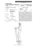 | 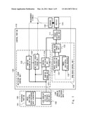 |
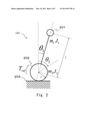 | 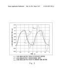 |
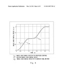 | 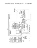 |
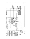 | 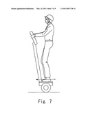 |
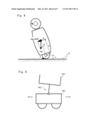 | 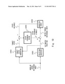 |
 |  |
| Similar patent applications: | |
| Date | Title |
|---|---|
| 2009-05-28 | Control device of an adjustment apparatus of a motor vehicle |
| 2009-04-16 | Method and system for controlling the loading of a container associated with a vehicle |
| 2009-07-02 | Control device module, especially in or for a motor vehicle |
| 2009-11-12 | Cruise control cancel device for passengers in vehicles |
| 2009-12-03 | Guided control device for unmanned vehicle |
| New patent applications in this class: | |
| Date | Title |
|---|---|
| 2022-05-05 | Real-time commercial vehicle weight measurement and use |
| 2022-05-05 | Vibration damping control apparatus |
| 2019-05-16 | Automated vehicle configuration |
| 2018-01-25 | Vehicle control apparatus, distance calculation apparatus, and distance calculation method |
| 2016-07-14 | Active damping system having electrically controlled actuator |
| New patent applications from these inventors: | |
| Date | Title |
|---|---|
| 2014-06-19 | Inverted vehicle control apparatus, and method and program therefor |
| 2013-01-10 | Vehicle control apparatus, control method thereof, and control software |
| 2012-01-05 | Robot apparatus and control method therefor |
| 2011-09-15 | Robot controller, robot control method, and legged robot |
| Top Inventors for class "Data processing: vehicles, navigation, and relative location" | |
| Rank | Inventor's name |
|---|---|
| 1 | Anthony H. Heap |
| 2 | Ajith Kuttannair Kumar |
| 3 | Christopher P. Ricci |
| 4 | Roderick A. Hyde |
| 5 | Lowell L. Wood, Jr. |