Patent application title: WATERPROOF PANEL FRAME STRUCTURE
Inventors:
Wen-Hung Huang (Taipei County, TW)
IPC8 Class: AA47B8100FI
USPC Class:
3122231
Class name: Supports: cabinet structure for particular electrical device or component
Publication date: 2011-03-24
Patent application number: 20110068664
structure comprises a front housing and a panel
supporter. The front housing and the panel supporter are matched with
each other to form conjunctive slants at right and left sides which slant
inward and to form conjunctive slants at upper and down sides which slant
downward. The front housing and the panel supporter comprise a groove and
a ridge matched with each other and disposed at the conjunctive position
between the front housing and the panel supporter for keeping water or
liquid from infiltrating under atmosphere pressure.Claims:
1. A waterproof panel frame structure for a flat panel display,
comprising:a display panel;a support frame disposed to surround the
display panel so as to fix the display panel;a front housing disposed on
the outer of the waterproof panel frame structure;a panel supporter
sandwiched between the front housing and the support frame, securely
fixed to the front housing, and snapped with the support frame, wherein
the front housing and the panel supporter are matched with each other to
form conjunctive slants at right and left sides of panel frame which
slant inward and conjunctive slants at upper and down sides of panel
frame which slant downward, and the front housing and the panel supporter
comprise a groove and a ridge matched with each other and disposed at a
conjunctive position between the front housing and the panel supporter;
anda protective cover closely attached to the display panel and securely
fixed to the panel supporter.
2. The waterproof panel frame structure as claimed in claim 1, wherein the groove and the ridge are disposed on the conjunctive slants, and closely matched with each other.
3. The waterproof panel frame structure as claimed in claim 1, wherein the groove and the ridge are disposed on the conjunctive slants and planes behind the conjunctive slants.
4. The waterproof panel frame structure as claimed in claim 1, wherein the groove and the ridge are in the shape of a closely-matched convex and a closely-matched concave.
5. The waterproof panel frame structure as claimed in claim 3, wherein the groove and the ridge are closely-matched zigzag in shape.Description:
BACKGROUND OF THE INVENTION
[0001]1. Technical Field
[0002]The present invention is related to a waterproof panel frame structure comprising a front housing and a panel supporter. The front housing and the panel supporter are matched with each other to form conjunctive slants at right and left sides of the panel frame which slant inward and conjunctive slants at upper and down sides of the panel frame which slant downward. The front housing and the panel supporter comprise a groove and a ridge matched with each other and disposed at the conjunctive position between the front housing and the panel supporter.
[0003]2. Description of the Related Art
[0004]The known waterproof structure for 3C electronic products all are suitable for being used under atmosphere pressure, some of them only provide waterproof function, and some of them provide anti-dust functions and even shockproof functions.
[0005]For example, United States Patent Application Publication No. 2008/0245452 A1, entitled "Weatherproofing Apparatus and Method for Cameras and Video Recorders,` discloses a waterproof apparatus having a groove and a ridge snapped and matched with each other so as to achieve the function of waterproofing. However, the disclosed waterproof apparatus can not be waterproofed for a long time, and there is still possibility of water infiltration.
[0006]Also, U.S. Pat. No. 5,125,175, entitled "Children's waterproof, safety picture frame,` discloses a picture frame capable of keeping the humidity in air or water in normal condition from infiltrating. However, a sealant and precise tolerance are necessary for achieving the waterproof function, so the manufacturing processes will be complex and costly.
[0007]Further, Taiwan utility model patent application No. 97212449 discloses a sealed waterproof structure, which uses a rectangular loop structure and a snapping-locking structure for providing sealing, anti-dust, waterproof, and shockproof functions. However, the disclosed structure also need to have elastic sealing material, such as rubber, for sealing, anti-dust and shockproof, and the manufacturing processes will be complex and costly.
SUMMARY OF THE INVENTION
[0008]It is a object of the present invention to provide a waterproof structure which can be manufactured without complex processes, is low in cost and simple in structure, and is able to keep water or liquid from infiltrating under atmosphere pressure.
[0009]The present invention provides a waterproof panel frame structure for a flat panel display comprising a display panel, a support frame, a front housing, a panel supporter, and a protective cover. The support frame is disposed to surround the display panel so as to fix the display panel. The front housing is disposed on the outer of the waterproof panel frame structure. The panel supporter is sandwiched between the front housing and the support frame, securely fixed to the front housing, and snapped with the support frame. The front housing and the panel supporter are matched with each other to form conjunctive slants at right and left sides of panel frame which slant inward and conjunctive slants at upper and down sides of panel frame which slant downward. The front housing and the panel supporter comprise a groove and a ridge matched with each other and disposed at the conjunctive position between the front housing and the panel supporter. The protective cover is closely attached to the display panel and securely fixed to the panel supporter.
[0010]Further, the groove and the ridge are disposed on the conjunctive slants of the front housing and the panel supporter, and closely matched with each other.
[0011]Further, the groove and the ridge are disposed on the conjunctive slants of the front housing and the panel supporter and on planes behind the conjunctive slants.
[0012]Further, the groove and the ridge are in the shape of a closely-matched convex and concave.
[0013]Still further, the groove and the ridge are closely-matched zigzag in shape.
[0014]The invention may best be understood by reference to the following description of the presently preferred embodiments together with the accompanying drawings.
BRIEF DESCRIPTION OF THE DRAWINGS
[0015]FIG. 1 is a top cross-sectional view of a waterproof panel frame structure according to an embodiment of the present invention.
[0016]FIG. 2 is an enlarged top cross-sectional view of the waterproof panel frame structure according to an embodiment of the present invention.
[0017]FIG. 3 is a side cross-sectional view of a waterproof panel frame structure according to an embodiment of the present invention.
[0018]FIG. 4 is an upper enlarged side cross-sectional view of a waterproof panel frame structure according to an embodiment of the present invention.
[0019]FIG. 5 is a lower enlarged side cross-sectional view of a waterproof panel frame structure according to an embodiment of the present invention.
[0020]FIG. 6 is a top cross-sectional view of a waterproof panel frame structure according to another embodiment of the present invention.
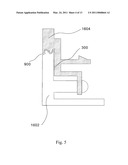
[0021]FIG. 7 is an enlarged top cross-sectional view of the waterproof panel frame structure according to another embodiment of the present invention.
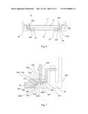
[0022]FIG. 8 is a side cross-sectional view of a waterproof panel frame structure according to another embodiment of the present invention.
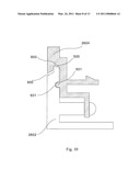
[0023]FIG. 9 is an upper enlarged side cross-sectional view of a waterproof panel frame structure according to another embodiment of the present invention.
[0024]FIG. 10 is a lower enlarged side cross-sectional view of a waterproof panel frame structure according to another embodiment of the present invention.
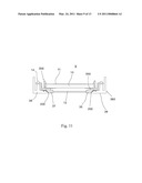
[0025]FIG. 11 is a top cross-sectional view of a waterproof panel frame structure according to still another embodiment of the present invention.
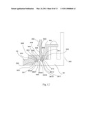
[0026]FIG. 12 is an enlarged top cross-sectional view of the waterproof panel frame structure according to still another embodiment of the present invention.
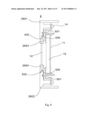
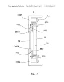
[0027]FIG. 13 is a side cross-sectional view of a waterproof panel frame structure according to still another embodiment of the present invention.
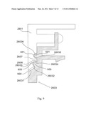
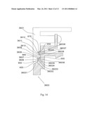
[0028]FIG. 14 is an upper enlarged side cross-sectional view of a waterproof panel frame structure according to still another embodiment of the present invention.
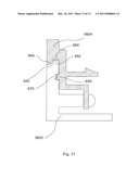
[0029]FIG. 15 is a lower enlarged side cross-sectional view of a waterproof panel frame structure according to still another embodiment of the present invention.
DETAILED DESCRIPTION OF THE INVENTION
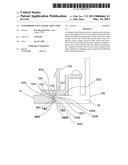
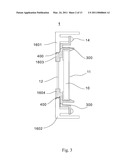
[0030]Referring to FIG. 1, FIG. 2, FIG. 3, a waterproof panel frame structure 1 according to a first embodiment of the present invention is shown, and comprises a display panel 10, a support frame 11, a protective cover 12, a front housing 160 and a panel supporter 150. The support frame 11 is disposed to surround the display panel 10 so as to fix the display panel 10. The protective cover 12 is disposed in front of the waterproof panel frame structure 1. The front housing 160 is disposed on the both sides of the waterproof panel frame structure 1. The panel supporter 150 is sandwiched between the front housing 160 and the support frame 11, securely fixed to the front housing 160 by means of fixing screws 14, and snapped with the support frame 11. An S-shaped conjunctive slant 200 is formed at the conjunction between the front housing 160 and the panel supporter 150, which are coupled to each other via a ridge 500 matching with a coupling groove 800, a groove 600 matching with a coupling ridge 700 and a coupling plane 300. The front housing 160 comprises a front housing right portion 16, a front housing left portion 18, a front housing upper portion 1601 and a front housing lower portion 1602. The panel supporter 150 also comprises a panel right supporter 15, a panel left supporter 17, a panel upper supporter 1603, and a panel lower supporter 1604.
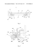
[0031]The panel right supporter 15 comprises the continuous ridge 500 and the continuous groove 600 along by the conjunctive slant 200. The ridge 500 and the panel right supporter 15 are formed at an acute angle so as to form a first waterproof convex 152 and a first waterproof reservoir 151. The groove 600 is formed as a third waterproof reservoir 156. A second waterproof reservoir 154 and a first turning angle 155 are formed between the ridge 500 and the groove 600. A second turning angle 157 is formed between the groove 600 and the coupling plane 300. As such, when water or liquid spills and infiltrates through an assembling gap 900, the infiltrating water flows along the conjunctive slant 200. The flow of the infiltrating water will be blocked by the first reservoir 151 until the infiltrating waster accumulates to certain volume and then turned to the first waterproof convex 152. Then, the flow of the infiltrating water will be blocked by the first waterproof convex 152 until the infiltrating water accumulates to certain volume and then flows over the first waterproof convex 152. Then, the flow of the infiltrating water will be blocked by a second reservoir 154 and the first turning angle 155. Then, if the flow of the infiltrating water further flows, it will be blocked by the continuous groove 600 until the infiltrating waster accumulates to certain volume. Then, before the flow of the infiltrating water or liquid flows to the coupling plane 300, it will be blocked by the third waterproof reservoir 156 and the second turning angle 157. In addition, the front housing right portion 16 is also provided with a groove 1605 and a ridge 1608 correspondent to the ridge 500 and the groove 600 of the panel right supporter 15, and is further provided with a first turning angle 1606 and the second turning angle 1607 disposed between the groove 1605 and the ridge 1608 so as to form the small and twisty assembling gap 900 for guiding and blocking the infiltrating water. The panel left supporter 17 and the front housing left portion 18 are matched with each other in the way similar to that described hereinbefore.
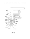
[0032]As shown in FIG. 3, FIG. 4, and FIG. 5, the panel upper supporter 1603 comprises the continuous ridge 500 and the continuous groove 600 along an extension slant 400. The ridge 500 is matched with the panel upper supporter 1603 at an acute angle so as to form a waterproof convex 16033 and a waterproof wall 16032 as well as an upper drain surface 16031 in front. The groove 600, therefore, is used to form a second reservoir 16036. A first reservoir 16034 and a first turning angle 16035 are formed between the ridge 500 and the groove 600. A second turning angle 16037 is formed between the groove 600 and the coupling plane 300. As such, when water or liquid spills and infiltrates through an assembling gap 900, the infiltrating water drains down away from the upper drain surface 16031. If the infiltrating water flows over the waterproof convex 16033, it will be blocked by the first reservoir 16034 and the first turning angle 16035 until the infiltrating waster accumulates to certain volume and then turned to the second reservoir 16036. In addition, the front housing upper portion 1601 also comprises a groove 1605 and a ridge 1608 correspondent to the ridge 500 and the groove 600 of the panel upper supporter 1603, and further comprises a first turning angle 1606, a second turning angle 1607, and a third turning angle 1609 disposed between the groove 1605 and the ridge 1608 so as to form the small and twisty assembling gap 900 for guiding and blocking the infiltrating water. The front housing lower portion 1602 and the panel lower supporter 1604 are matched with each other in the way similar to that described hereinbefore, and the only difference is that the coupling plane 300 is disposed on the lower right side of the extension slant 400.
[0033]Referring to FIG. 6, FIG. 7, and FIG. 8, a waterproof panel frame structure 2 according to a second embodiment of the present invention is shown, and comprises a display panel 10, a support frame 11, a protective cover 12, a front housing 260 and a panel supporter 250. The display panel 10, the support frame 11, the protective cover 12, the front housing 260 and the panel supporter 250 are assembled in the way similar to that described in the first embodiment, and, for purposes of brevity and clarity, the assembling position thereof will not be repetitively described.
[0034]The panel right supporter 25 comprises the continuous ridge 500 and a vertical ridge 502 along by the conjunctive slant 200. The ridge 500 and the panel right supporter 25 are formed in an acute angle so as to form a first waterproof convex 253, a waterproof wall 252 and a waterproof reservoir 251. The vertical ridge 502 is used to form a second waterproof convex 256. A second turning angle 255 and a first turning angle 254 are formed between the ridge 500 and the vertical ridge 502, and a third turning angle 257 is formed between the vertical ridge 502 and the coupling plane 300. As such, when water or liquid spills and infiltrates through the assembling gap 900, the infiltrating water flows along the conjunctive slant 200. The flow of the infiltrating water will be blocked by the reservoir 251 until the infiltrating waster accumulates to certain volume and then turned to the waterproof wall 252. Then, the flow of the infiltrating water will be blocked by the first waterproof convex 253 until the infiltrating waster accumulates to certain volume and then flows over the first waterproof convex 253. Then, the flow of the infiltrating water will tarry at the second turning angle 255 and the first turning angle 254. If the flow of the infiltrating water flows further, the flow will be blocked by the second waterproof convex 256 and then flows over the second waterproof convex 256 to the coupling plane 300. In addition, the front housing 260 is also provided with a groove 600 and a horizontal groove 601 correspondent to the ridge 500 and the vertical ridge 502 of the panel right supporter 25, and is further provided with a first turning angle 2606, a second turning angle 2607, and a third turning angle 2608 disposed between the groove 600 and the horizontal groove 601 so as to form the small and twisty assembling gap 900 for guiding and blocking the infiltrating water. The panel left supporter 27 and the front housing left portion 28 are matched with each other in the way similar to that described hereinbefore.
[0035]As shown in FIG. 8, FIG. 9, and FIG. 10, the panel upper supporter 2603 comprises the continuous ridge 500 and a horizontal ridge 501 along an extension slant 400. The ridge 500 is matched with the panel upper supporter 2603 at an acute angle so as to form a waterproof wall 26032 and a waterproof convex 26033 as well as an upper drain surface 26031 in front. The horizontal ridge 501 is used to form a second waterproof convex 26036. A first turning angle 26034 and a second turning angle 26035 are formed between the ridge 500 and the horizontal ridge 501. As such, when water or liquid spills and infiltrates through an assembling gap 900, the infiltrating water drains down away from the upper drain surface 26031. If the infiltrating water flows over the waterproof convex 26033, it will be blocked by the waterproof wall 26032 and the waterproof convex 26033 until the infiltrating waster accumulates to certain volume, and then flows and tarries at the position between the first turning angle 26034 and the second turning angle 26035 and is blocked by the second waterproof convex 26036. In addition, the front housing upper portion 2601 also comprises a groove 600 and a horizontal groove 601 correspondent to the ridge 500 and the horizontal ridge 501 of the panel upper supporter 2603, and further comprises a first turning angle 2606 and a second turning angle 2607 disposed between the groove 600 and the horizontal groove 601 so as to form the small and twisty assembling gap 900 for guiding and blocking the infiltrating water. The front housing lower portion 2602 and the panel lower supporter 2604 are matched with each other in the way similar to that described hereinbefore, and the only difference is that the panel lower supporter 2604 comprises the groove 600 and the horizontal groove 601, and the front housing lower portion 2602 comprises correspondingly the ridge 500 and the horizontal ridge 501.
[0036]Referring to FIG. 11, a waterproof panel frame structure 3 according to a third embodiment of the present invention is shown, and comprises a display panel 10, a support frame 11, a protective cover 12, a front housing 360 and a panel supporter 350. The display panel 10, the support frame 11, the protective cover 12, the front housing 360 and the panel supporter 350 are assembled in the way similar to that described in the first embodiment, and, for purposes of brevity and clarity, the assembling position thereof will not be repetitively described.
[0037]As shown in FIG. 11 and FIG. 12, the panel right supporter 35 comprises a continuous forked ridge 550 and a continuous vertical forked ridge 552, which both are zigzag in shape, along by the conjunctive slant 200. The forked ridge 550 and the panel right supporter 35 are formed in an acute angle so as to form a first waterproof convex 352 and a waterproof reservoir 351 as well as a second waterproof convex 354 and a second waterproof reservoir 353 at a slightly upper position. The vertical forked ridge 552 is used to form a third waterproof convex 355 and a third waterproof reservoir 356 as well as a fourth waterproof convex 357 at a slightly upper position. A second turning angle 359 and a first turning angle 358 are formed between the forked ridge 550 and the vertical forked ridge 552. As such, when water or liquid spills and infiltrates through the assembling gap 900, the infiltrating water flows along the conjunctive slant 200. The flow of the infiltrating water will be blocked by the reservoir 351 until the infiltrating waster accumulates to certain volume and then turned to the waterproof convex 352. Then, the flow of the infiltrating water will be blocked by the waterproof convex 352 until the infiltrating waster accumulates to certain volume and then flows over the waterproof convex 352. Then, the flow of the infiltrating water will be blocked by the second waterproof reservoir 353 and the second waterproof convex 354 before the flow tarries at the position between the first turning angle 358 and the second turning angle 359. If the flow of the infiltrating water flows further, the flow will be blocked by the third waterproof convex 355, the third waterproof reservoir 356, and the fourth waterproof convex 357 of the horizontal ridge 650 before the flow reaches the coupling plane 300. In addition, the front housing right portion 36 is also provided with a groove 660 and a horizontal groove 670 correspondent to the forked ridge 550 and the vertical forked ridge 552 of the panel right supporter 35, and is further provided with a first turning angle 3606, a second turning angle 3607, a third turning angle 3608, a fourth turning angle 3609, a fifth turning angle 3610, a sixth turning angle 3611, and a seventh turning angle 3612 disposed between the groove 660 and the horizontal groove 670 so as to form the small and twisty assembling gap 900 for guiding and blocking the infiltrating water. The panel left supporter 37 and the front housing left portion 38 are matched with each other in the way similar to that described hereinbefore.
[0038]As shown in FIG. 13, FIG. 14, and FIG. 15, the panel upper supporter 3603 comprises the forked ridge 550 and a horizontal ridge 650 along an extension slant 400. The forked ridge 550 is matched with the panel upper supporter 3603 at an acute angle so as to form a waterproof wall 36032 and a waterproof convex 36033 as well as a second waterproof convex 36035 and a first turning angle 36034 at the slightly upper position of the waterproof wall 36032. An upper drain surface 36031 is formed at the front of the waterproof wall 36032. The horizontal ridge 650 is used to form a third waterproof convex 36037, a fourth waterproof convex 36038, and a fourth turning angle 36040. A second turning angle 36036 and a third turning angle 36039 are formed between the forked ridge 550 and the horizontal ridge 650. As such, when water or liquid spills and infiltrates through an assembling gap 900, the infiltrating water drains down away from the upper drain surface 36031. If the infiltrating water flows over the waterproof convex 36033, it will be blocked by the waterproof wall 36032 and the waterproof convex 36033 until the infiltrating waster accumulates to certain volume, and then flows over the second waterproof convex 36035, tarries at the position between the second turning angle 36036 and the third turning angle 36039 and is blocked by the third waterproof convex 36037 and the fourth waterproof convex 36038. In addition, the front housing upper portion 3601 also comprises a groove 660 and a horizontal groove 670 correspondent to the forked ridge 550 and the horizontal ridge 650 of the panel upper supporter 3603, and further comprises a first turning angle 3606, a second turning angle 3607, a third turning angle 3608, a fourth turning angle 3609, a fifth turning angle 3610, a sixth turning angle 3611, and a seven turning angle 3612 disposed between the groove 660 and the horizontal groove 670 so as to form the small and twisty assembling gap 900 for guiding and blocking the infiltrating water. The front housing lower portion 3602 and the panel lower supporter 3604 are matched with each other in the way similar to that described hereinbefore, and the only difference is that the front housing lower portion 3602 comprises the forked ridge 550 and the horizontal groove 670, and the panel lower supporter 3604 comprises correspondingly the groove 660 and the horizontal ridge 650.
[0039]While the invention has been described by way of example and in terms of preferred embodiment, it is to be understood that the invention is not limited thereto. To the contrary, it is intended to cover various modifications and similar arrangements (as would be apparent to those skilled in the art). Therefore, the scope of the appended claims should be accorded the broadest interpretation so as to encompass all such modifications and similar arrangements.
Claims:
1. A waterproof panel frame structure for a flat panel display,
comprising:a display panel;a support frame disposed to surround the
display panel so as to fix the display panel;a front housing disposed on
the outer of the waterproof panel frame structure;a panel supporter
sandwiched between the front housing and the support frame, securely
fixed to the front housing, and snapped with the support frame, wherein
the front housing and the panel supporter are matched with each other to
form conjunctive slants at right and left sides of panel frame which
slant inward and conjunctive slants at upper and down sides of panel
frame which slant downward, and the front housing and the panel supporter
comprise a groove and a ridge matched with each other and disposed at a
conjunctive position between the front housing and the panel supporter;
anda protective cover closely attached to the display panel and securely
fixed to the panel supporter.
2. The waterproof panel frame structure as claimed in claim 1, wherein the groove and the ridge are disposed on the conjunctive slants, and closely matched with each other.
3. The waterproof panel frame structure as claimed in claim 1, wherein the groove and the ridge are disposed on the conjunctive slants and planes behind the conjunctive slants.
4. The waterproof panel frame structure as claimed in claim 1, wherein the groove and the ridge are in the shape of a closely-matched convex and a closely-matched concave.
5. The waterproof panel frame structure as claimed in claim 3, wherein the groove and the ridge are closely-matched zigzag in shape.
Description:
BACKGROUND OF THE INVENTION
[0001]1. Technical Field
[0002]The present invention is related to a waterproof panel frame structure comprising a front housing and a panel supporter. The front housing and the panel supporter are matched with each other to form conjunctive slants at right and left sides of the panel frame which slant inward and conjunctive slants at upper and down sides of the panel frame which slant downward. The front housing and the panel supporter comprise a groove and a ridge matched with each other and disposed at the conjunctive position between the front housing and the panel supporter.
[0003]2. Description of the Related Art
[0004]The known waterproof structure for 3C electronic products all are suitable for being used under atmosphere pressure, some of them only provide waterproof function, and some of them provide anti-dust functions and even shockproof functions.
[0005]For example, United States Patent Application Publication No. 2008/0245452 A1, entitled "Weatherproofing Apparatus and Method for Cameras and Video Recorders,` discloses a waterproof apparatus having a groove and a ridge snapped and matched with each other so as to achieve the function of waterproofing. However, the disclosed waterproof apparatus can not be waterproofed for a long time, and there is still possibility of water infiltration.
[0006]Also, U.S. Pat. No. 5,125,175, entitled "Children's waterproof, safety picture frame,` discloses a picture frame capable of keeping the humidity in air or water in normal condition from infiltrating. However, a sealant and precise tolerance are necessary for achieving the waterproof function, so the manufacturing processes will be complex and costly.
[0007]Further, Taiwan utility model patent application No. 97212449 discloses a sealed waterproof structure, which uses a rectangular loop structure and a snapping-locking structure for providing sealing, anti-dust, waterproof, and shockproof functions. However, the disclosed structure also need to have elastic sealing material, such as rubber, for sealing, anti-dust and shockproof, and the manufacturing processes will be complex and costly.
SUMMARY OF THE INVENTION
[0008]It is a object of the present invention to provide a waterproof structure which can be manufactured without complex processes, is low in cost and simple in structure, and is able to keep water or liquid from infiltrating under atmosphere pressure.
[0009]The present invention provides a waterproof panel frame structure for a flat panel display comprising a display panel, a support frame, a front housing, a panel supporter, and a protective cover. The support frame is disposed to surround the display panel so as to fix the display panel. The front housing is disposed on the outer of the waterproof panel frame structure. The panel supporter is sandwiched between the front housing and the support frame, securely fixed to the front housing, and snapped with the support frame. The front housing and the panel supporter are matched with each other to form conjunctive slants at right and left sides of panel frame which slant inward and conjunctive slants at upper and down sides of panel frame which slant downward. The front housing and the panel supporter comprise a groove and a ridge matched with each other and disposed at the conjunctive position between the front housing and the panel supporter. The protective cover is closely attached to the display panel and securely fixed to the panel supporter.
[0010]Further, the groove and the ridge are disposed on the conjunctive slants of the front housing and the panel supporter, and closely matched with each other.
[0011]Further, the groove and the ridge are disposed on the conjunctive slants of the front housing and the panel supporter and on planes behind the conjunctive slants.
[0012]Further, the groove and the ridge are in the shape of a closely-matched convex and concave.
[0013]Still further, the groove and the ridge are closely-matched zigzag in shape.
[0014]The invention may best be understood by reference to the following description of the presently preferred embodiments together with the accompanying drawings.
BRIEF DESCRIPTION OF THE DRAWINGS
[0015]FIG. 1 is a top cross-sectional view of a waterproof panel frame structure according to an embodiment of the present invention.
[0016]FIG. 2 is an enlarged top cross-sectional view of the waterproof panel frame structure according to an embodiment of the present invention.
[0017]FIG. 3 is a side cross-sectional view of a waterproof panel frame structure according to an embodiment of the present invention.
[0018]FIG. 4 is an upper enlarged side cross-sectional view of a waterproof panel frame structure according to an embodiment of the present invention.
[0019]FIG. 5 is a lower enlarged side cross-sectional view of a waterproof panel frame structure according to an embodiment of the present invention.
[0020]FIG. 6 is a top cross-sectional view of a waterproof panel frame structure according to another embodiment of the present invention.
[0021]FIG. 7 is an enlarged top cross-sectional view of the waterproof panel frame structure according to another embodiment of the present invention.
[0022]FIG. 8 is a side cross-sectional view of a waterproof panel frame structure according to another embodiment of the present invention.
[0023]FIG. 9 is an upper enlarged side cross-sectional view of a waterproof panel frame structure according to another embodiment of the present invention.
[0024]FIG. 10 is a lower enlarged side cross-sectional view of a waterproof panel frame structure according to another embodiment of the present invention.
[0025]FIG. 11 is a top cross-sectional view of a waterproof panel frame structure according to still another embodiment of the present invention.
[0026]FIG. 12 is an enlarged top cross-sectional view of the waterproof panel frame structure according to still another embodiment of the present invention.
[0027]FIG. 13 is a side cross-sectional view of a waterproof panel frame structure according to still another embodiment of the present invention.
[0028]FIG. 14 is an upper enlarged side cross-sectional view of a waterproof panel frame structure according to still another embodiment of the present invention.
[0029]FIG. 15 is a lower enlarged side cross-sectional view of a waterproof panel frame structure according to still another embodiment of the present invention.
DETAILED DESCRIPTION OF THE INVENTION
[0030]Referring to FIG. 1, FIG. 2, FIG. 3, a waterproof panel frame structure 1 according to a first embodiment of the present invention is shown, and comprises a display panel 10, a support frame 11, a protective cover 12, a front housing 160 and a panel supporter 150. The support frame 11 is disposed to surround the display panel 10 so as to fix the display panel 10. The protective cover 12 is disposed in front of the waterproof panel frame structure 1. The front housing 160 is disposed on the both sides of the waterproof panel frame structure 1. The panel supporter 150 is sandwiched between the front housing 160 and the support frame 11, securely fixed to the front housing 160 by means of fixing screws 14, and snapped with the support frame 11. An S-shaped conjunctive slant 200 is formed at the conjunction between the front housing 160 and the panel supporter 150, which are coupled to each other via a ridge 500 matching with a coupling groove 800, a groove 600 matching with a coupling ridge 700 and a coupling plane 300. The front housing 160 comprises a front housing right portion 16, a front housing left portion 18, a front housing upper portion 1601 and a front housing lower portion 1602. The panel supporter 150 also comprises a panel right supporter 15, a panel left supporter 17, a panel upper supporter 1603, and a panel lower supporter 1604.
[0031]The panel right supporter 15 comprises the continuous ridge 500 and the continuous groove 600 along by the conjunctive slant 200. The ridge 500 and the panel right supporter 15 are formed at an acute angle so as to form a first waterproof convex 152 and a first waterproof reservoir 151. The groove 600 is formed as a third waterproof reservoir 156. A second waterproof reservoir 154 and a first turning angle 155 are formed between the ridge 500 and the groove 600. A second turning angle 157 is formed between the groove 600 and the coupling plane 300. As such, when water or liquid spills and infiltrates through an assembling gap 900, the infiltrating water flows along the conjunctive slant 200. The flow of the infiltrating water will be blocked by the first reservoir 151 until the infiltrating waster accumulates to certain volume and then turned to the first waterproof convex 152. Then, the flow of the infiltrating water will be blocked by the first waterproof convex 152 until the infiltrating water accumulates to certain volume and then flows over the first waterproof convex 152. Then, the flow of the infiltrating water will be blocked by a second reservoir 154 and the first turning angle 155. Then, if the flow of the infiltrating water further flows, it will be blocked by the continuous groove 600 until the infiltrating waster accumulates to certain volume. Then, before the flow of the infiltrating water or liquid flows to the coupling plane 300, it will be blocked by the third waterproof reservoir 156 and the second turning angle 157. In addition, the front housing right portion 16 is also provided with a groove 1605 and a ridge 1608 correspondent to the ridge 500 and the groove 600 of the panel right supporter 15, and is further provided with a first turning angle 1606 and the second turning angle 1607 disposed between the groove 1605 and the ridge 1608 so as to form the small and twisty assembling gap 900 for guiding and blocking the infiltrating water. The panel left supporter 17 and the front housing left portion 18 are matched with each other in the way similar to that described hereinbefore.
[0032]As shown in FIG. 3, FIG. 4, and FIG. 5, the panel upper supporter 1603 comprises the continuous ridge 500 and the continuous groove 600 along an extension slant 400. The ridge 500 is matched with the panel upper supporter 1603 at an acute angle so as to form a waterproof convex 16033 and a waterproof wall 16032 as well as an upper drain surface 16031 in front. The groove 600, therefore, is used to form a second reservoir 16036. A first reservoir 16034 and a first turning angle 16035 are formed between the ridge 500 and the groove 600. A second turning angle 16037 is formed between the groove 600 and the coupling plane 300. As such, when water or liquid spills and infiltrates through an assembling gap 900, the infiltrating water drains down away from the upper drain surface 16031. If the infiltrating water flows over the waterproof convex 16033, it will be blocked by the first reservoir 16034 and the first turning angle 16035 until the infiltrating waster accumulates to certain volume and then turned to the second reservoir 16036. In addition, the front housing upper portion 1601 also comprises a groove 1605 and a ridge 1608 correspondent to the ridge 500 and the groove 600 of the panel upper supporter 1603, and further comprises a first turning angle 1606, a second turning angle 1607, and a third turning angle 1609 disposed between the groove 1605 and the ridge 1608 so as to form the small and twisty assembling gap 900 for guiding and blocking the infiltrating water. The front housing lower portion 1602 and the panel lower supporter 1604 are matched with each other in the way similar to that described hereinbefore, and the only difference is that the coupling plane 300 is disposed on the lower right side of the extension slant 400.
[0033]Referring to FIG. 6, FIG. 7, and FIG. 8, a waterproof panel frame structure 2 according to a second embodiment of the present invention is shown, and comprises a display panel 10, a support frame 11, a protective cover 12, a front housing 260 and a panel supporter 250. The display panel 10, the support frame 11, the protective cover 12, the front housing 260 and the panel supporter 250 are assembled in the way similar to that described in the first embodiment, and, for purposes of brevity and clarity, the assembling position thereof will not be repetitively described.
[0034]The panel right supporter 25 comprises the continuous ridge 500 and a vertical ridge 502 along by the conjunctive slant 200. The ridge 500 and the panel right supporter 25 are formed in an acute angle so as to form a first waterproof convex 253, a waterproof wall 252 and a waterproof reservoir 251. The vertical ridge 502 is used to form a second waterproof convex 256. A second turning angle 255 and a first turning angle 254 are formed between the ridge 500 and the vertical ridge 502, and a third turning angle 257 is formed between the vertical ridge 502 and the coupling plane 300. As such, when water or liquid spills and infiltrates through the assembling gap 900, the infiltrating water flows along the conjunctive slant 200. The flow of the infiltrating water will be blocked by the reservoir 251 until the infiltrating waster accumulates to certain volume and then turned to the waterproof wall 252. Then, the flow of the infiltrating water will be blocked by the first waterproof convex 253 until the infiltrating waster accumulates to certain volume and then flows over the first waterproof convex 253. Then, the flow of the infiltrating water will tarry at the second turning angle 255 and the first turning angle 254. If the flow of the infiltrating water flows further, the flow will be blocked by the second waterproof convex 256 and then flows over the second waterproof convex 256 to the coupling plane 300. In addition, the front housing 260 is also provided with a groove 600 and a horizontal groove 601 correspondent to the ridge 500 and the vertical ridge 502 of the panel right supporter 25, and is further provided with a first turning angle 2606, a second turning angle 2607, and a third turning angle 2608 disposed between the groove 600 and the horizontal groove 601 so as to form the small and twisty assembling gap 900 for guiding and blocking the infiltrating water. The panel left supporter 27 and the front housing left portion 28 are matched with each other in the way similar to that described hereinbefore.
[0035]As shown in FIG. 8, FIG. 9, and FIG. 10, the panel upper supporter 2603 comprises the continuous ridge 500 and a horizontal ridge 501 along an extension slant 400. The ridge 500 is matched with the panel upper supporter 2603 at an acute angle so as to form a waterproof wall 26032 and a waterproof convex 26033 as well as an upper drain surface 26031 in front. The horizontal ridge 501 is used to form a second waterproof convex 26036. A first turning angle 26034 and a second turning angle 26035 are formed between the ridge 500 and the horizontal ridge 501. As such, when water or liquid spills and infiltrates through an assembling gap 900, the infiltrating water drains down away from the upper drain surface 26031. If the infiltrating water flows over the waterproof convex 26033, it will be blocked by the waterproof wall 26032 and the waterproof convex 26033 until the infiltrating waster accumulates to certain volume, and then flows and tarries at the position between the first turning angle 26034 and the second turning angle 26035 and is blocked by the second waterproof convex 26036. In addition, the front housing upper portion 2601 also comprises a groove 600 and a horizontal groove 601 correspondent to the ridge 500 and the horizontal ridge 501 of the panel upper supporter 2603, and further comprises a first turning angle 2606 and a second turning angle 2607 disposed between the groove 600 and the horizontal groove 601 so as to form the small and twisty assembling gap 900 for guiding and blocking the infiltrating water. The front housing lower portion 2602 and the panel lower supporter 2604 are matched with each other in the way similar to that described hereinbefore, and the only difference is that the panel lower supporter 2604 comprises the groove 600 and the horizontal groove 601, and the front housing lower portion 2602 comprises correspondingly the ridge 500 and the horizontal ridge 501.
[0036]Referring to FIG. 11, a waterproof panel frame structure 3 according to a third embodiment of the present invention is shown, and comprises a display panel 10, a support frame 11, a protective cover 12, a front housing 360 and a panel supporter 350. The display panel 10, the support frame 11, the protective cover 12, the front housing 360 and the panel supporter 350 are assembled in the way similar to that described in the first embodiment, and, for purposes of brevity and clarity, the assembling position thereof will not be repetitively described.
[0037]As shown in FIG. 11 and FIG. 12, the panel right supporter 35 comprises a continuous forked ridge 550 and a continuous vertical forked ridge 552, which both are zigzag in shape, along by the conjunctive slant 200. The forked ridge 550 and the panel right supporter 35 are formed in an acute angle so as to form a first waterproof convex 352 and a waterproof reservoir 351 as well as a second waterproof convex 354 and a second waterproof reservoir 353 at a slightly upper position. The vertical forked ridge 552 is used to form a third waterproof convex 355 and a third waterproof reservoir 356 as well as a fourth waterproof convex 357 at a slightly upper position. A second turning angle 359 and a first turning angle 358 are formed between the forked ridge 550 and the vertical forked ridge 552. As such, when water or liquid spills and infiltrates through the assembling gap 900, the infiltrating water flows along the conjunctive slant 200. The flow of the infiltrating water will be blocked by the reservoir 351 until the infiltrating waster accumulates to certain volume and then turned to the waterproof convex 352. Then, the flow of the infiltrating water will be blocked by the waterproof convex 352 until the infiltrating waster accumulates to certain volume and then flows over the waterproof convex 352. Then, the flow of the infiltrating water will be blocked by the second waterproof reservoir 353 and the second waterproof convex 354 before the flow tarries at the position between the first turning angle 358 and the second turning angle 359. If the flow of the infiltrating water flows further, the flow will be blocked by the third waterproof convex 355, the third waterproof reservoir 356, and the fourth waterproof convex 357 of the horizontal ridge 650 before the flow reaches the coupling plane 300. In addition, the front housing right portion 36 is also provided with a groove 660 and a horizontal groove 670 correspondent to the forked ridge 550 and the vertical forked ridge 552 of the panel right supporter 35, and is further provided with a first turning angle 3606, a second turning angle 3607, a third turning angle 3608, a fourth turning angle 3609, a fifth turning angle 3610, a sixth turning angle 3611, and a seventh turning angle 3612 disposed between the groove 660 and the horizontal groove 670 so as to form the small and twisty assembling gap 900 for guiding and blocking the infiltrating water. The panel left supporter 37 and the front housing left portion 38 are matched with each other in the way similar to that described hereinbefore.
[0038]As shown in FIG. 13, FIG. 14, and FIG. 15, the panel upper supporter 3603 comprises the forked ridge 550 and a horizontal ridge 650 along an extension slant 400. The forked ridge 550 is matched with the panel upper supporter 3603 at an acute angle so as to form a waterproof wall 36032 and a waterproof convex 36033 as well as a second waterproof convex 36035 and a first turning angle 36034 at the slightly upper position of the waterproof wall 36032. An upper drain surface 36031 is formed at the front of the waterproof wall 36032. The horizontal ridge 650 is used to form a third waterproof convex 36037, a fourth waterproof convex 36038, and a fourth turning angle 36040. A second turning angle 36036 and a third turning angle 36039 are formed between the forked ridge 550 and the horizontal ridge 650. As such, when water or liquid spills and infiltrates through an assembling gap 900, the infiltrating water drains down away from the upper drain surface 36031. If the infiltrating water flows over the waterproof convex 36033, it will be blocked by the waterproof wall 36032 and the waterproof convex 36033 until the infiltrating waster accumulates to certain volume, and then flows over the second waterproof convex 36035, tarries at the position between the second turning angle 36036 and the third turning angle 36039 and is blocked by the third waterproof convex 36037 and the fourth waterproof convex 36038. In addition, the front housing upper portion 3601 also comprises a groove 660 and a horizontal groove 670 correspondent to the forked ridge 550 and the horizontal ridge 650 of the panel upper supporter 3603, and further comprises a first turning angle 3606, a second turning angle 3607, a third turning angle 3608, a fourth turning angle 3609, a fifth turning angle 3610, a sixth turning angle 3611, and a seven turning angle 3612 disposed between the groove 660 and the horizontal groove 670 so as to form the small and twisty assembling gap 900 for guiding and blocking the infiltrating water. The front housing lower portion 3602 and the panel lower supporter 3604 are matched with each other in the way similar to that described hereinbefore, and the only difference is that the front housing lower portion 3602 comprises the forked ridge 550 and the horizontal groove 670, and the panel lower supporter 3604 comprises correspondingly the groove 660 and the horizontal ridge 650.
[0039]While the invention has been described by way of example and in terms of preferred embodiment, it is to be understood that the invention is not limited thereto. To the contrary, it is intended to cover various modifications and similar arrangements (as would be apparent to those skilled in the art). Therefore, the scope of the appended claims should be accorded the broadest interpretation so as to encompass all such modifications and similar arrangements.
User Contributions:
Comment about this patent or add new information about this topic:
| People who visited this patent also read: | |
| Patent application number | Title |
|---|---|
| 20110072302 | SOLID STATE MEMORY CARTRIDGE WITH WEAR INDICATION |
| 20110072301 | SYSTEMS AND METHODS FOR RECOVERING MEMORY |
| 20110072300 | TEARING-PROOF METHOD FOR WRITING DATA IN A NONVOLATILE MEMORY |
| 20110072299 | LEAK MONITORING SYSTEM AND ASSOCIATED METHODS |
| 20110072298 | Information processing device, transfer circuit and error controlling method for information processing device |
Images included with this patent application:
 |  |
 |  |
 |  |
 |  |
 |  |
 |  |
 |  |
| Similar patent applications: | |
| Date | Title |
|---|---|
| 2010-09-16 | Stowable and releasably securable mobile structure |
| 2009-12-17 | Pull-out shelf for use in a confined space formed in a structure |
| 2011-06-30 | Waterproof housing structure for portable optical analyzer |
| 2008-11-20 | Space-suit matable enclosure providing workspace for astronauts |
| 2009-04-23 | Cable management apparatus, system, and furniture structures |
| New patent applications in this class: | |
| Date | Title |
|---|---|
| 2016-07-07 | Frame for forming image forming apparatus and manufacturing method of the frame |
| 2016-06-30 | Injection-molded case for electronic communication products |
| 2016-06-16 | Housing for electronic control unit |
| 2016-04-28 | Slidable engagement of enclosure housings |
| 2016-04-21 | Electronic device enclosure |
| New patent applications from these inventors: | |
| Date | Title |
|---|---|
| 2012-09-06 | Portable electronic device able to measure weight |
| 2012-04-26 | Display device with juice extracting function |
| 2012-03-29 | Flexible support structure |
| 2011-12-15 | Display device |
| 2011-07-14 | Computer with electric heating unit |
| Top Inventors for class "Supports: cabinet structure" | |
| Rank | Inventor's name |
|---|---|
| 1 | Yun-Lung Chen |
| 2 | Karl-Friedrich Laible |
| 3 | Jae Hoon Lim |
| 4 | Chen-Lu Fan |
| 5 | Wen-Tang Peng |