Patent application title: ANTI-SPILL VESSEL
Inventors:
John Norender Kumar Lalwani (Kowloon, HK)
Assignees:
Arismel Group Limited
IPC8 Class: AA47G1902FI
USPC Class:
220574
Class name: Receptacles table dish (e.g., plate, bowl, platter, etc.)
Publication date: 2011-03-10
Patent application number: 20110056958
Inventors list |
Agents list |
Assignees list |
List by place |
Classification tree browser |
Top 100 Inventors |
Top 100 Agents |
Top 100 Assignees |
Usenet FAQ Index |
Documents |
Other FAQs |
Patent application title: ANTI-SPILL VESSEL
Inventors:
John Norender Kumar Lalwani
Agents:
Assignees:
Origin: ,
IPC8 Class: AA47G1902FI
USPC Class:
Publication date: 03/10/2011
Patent application number: 20110056958
Abstract:
The anti-spill vessel for use on a support surface of a table, has a bowl
with a first screw-threaded portion, and a base which includes a second
screw-threaded portion The first screw-threaded portion is releasably
inter-engageable with the second screw-threaded portion such that the
bowl can be attached to the base. There is also a belt extending from the
base for fastening upon the support surface so as to releasably connect
the base to the table.Claims:
1. An anti-spill vessel for use on a support surface of a table
comprising:a receptacle having a first attachment portion;a base
including a second attachment portion which is releasably
inter-engageable with the first attachment portion such that the
receptacle is attached to the base; andan elongate pliable connector
extending from the base for fastening upon a said support surface so as
to releasably connect the base to a said table.
2. The anti-spill vessel as claimed in claim 1, wherein the first attachment portion and the second attachment portion are inter-engageable through relative rotation about a vertical axis.
3. The anti-spill vessel as claimed in claim 1, wherein the elongate pliable connector is connectable to all possible variations in design or nature of the table.
4. The anti-spill vessel as claimed in claim 1, wherein the elongate pliable connector has two free ends each provided with a part of a two-part fastener, the two parts being co-operable to fasten the elongate pliable connector upon the support surface so as to releasably connect the base onto the table.
5. The anti-spill vessel as claimed in claim 1, wherein the first attachment portion is a seat extending downwardly from a bottom of the receptacle, the seat being internally threaded, and the second attachment portion is a platform atop a bottom of the base, the platform being externally threaded for inter-engagement with the seat of the base through relative rotation.
6. The anti-spill vessel as claimed in claim 5, wherein the base has a circular groove surrounding the platform, the groove being conformed to accommodate the seat.
7. The anti-spill vessel as claimed in claim 1, wherein the base has an aperture, the elongate pliable connector extending through the aperture and hence connected with the base.
8. The anti-spill vessel as claimed in claim 7, wherein the base has two said apertures on opposite sides of the base, through both of which the elongate pliable connector extends.
9. The anti-spill vessel as claimed in claim 8, wherein the elongate pliable connector comprises two separate belts, each being attached to one of the apertures.
10. The anti-spill vessel as claimed in claim 7, wherein each aperture is provided by a loop on a periphery of the base.
11. The anti-spill vessel as claimed in claim 1, wherein the base is wider than a bottom of the receptacle, acting as a wider bottom of the receptacle for stability.
12. The anti-spill vessel as claimed in claim 1, wherein the receptacle comprises a bowl.
Description:
[0001]The present invention relates generally to an anti-spill vessel and
more specifically to an anti-spill vessel which is convenient to use.
BACKGROUND OF THE INVENTION
[0002]Knocking over utensils and in particular vessels in use by accident is unavoidable and may cause troubles or even scorching. The issue is that these utensils are not properly secured or locked in their normal position. Knocking over utensils causes breakage or substances inside the utensils to fall or to spill out.
[0003]Particularly with children who are determined to feed themselves before they have the level of co-ordination required to use a spoon or any utensil. They end up at the end of a meal wearing most of it.
[0004]The invention of securely retaining vessels has many applications. The invention is not only useful for children who tend to move or to knock over bowls and cups, but also beneficial to adults with control deficiencies in handling the unsecured vessels. Further, using unsecured vessels in a moving environment such as in a vehicle, watercraft, aircraft, spacecraft or other moving environments will easily cause dislocating of the vessels or spillage of the substances in the vessels.
[0005]To overcome the problem, it is known to mount a bowl onto a base which is connected directly onto the table by one or more screws. There are however disadvantages. The table surface is unavoidably damaged because holes are drilled in or through the table for the screws, and drilling holes is cumbersome. Also, the base is not readily removable for cleaning.
OBJECT OF THE INVENTION
[0006]It is an object of the present invention to overcome or substantially ameliorate at least one of the above disadvantages and/or more generally to provide an anti-spill vessel which is convenient to use.
SUMMARY OF THE INVENTION
[0007]According to the invention, there is provided an anti-spill vessel for use on a support surface of a table comprising a receptacle having a first attachment portion, a base including a second attachment portion which is releasably inter-engageable with the first attachment portion such that the receptacle is attached to the base; and an elongate pliable connector extending from the base for fastening upon a said support surface so as to releasably connect the base to a said table.
[0008]Preferably, the first attachment portion and the second attachment portion are inter-engageable through relative rotation about a vertical axis.
[0009]More preferably, the elongate pliable connector is connectable to all possible variations in design or nature of the table.
[0010]Further more preferably, the elongate pliable connector has two free ends each provided with a part of a two-part fastener, the two parts being co-operable to fasten the elongate pliable connector upon the support surface so as to releasably connect the base onto the table.
[0011]Preferably, the first attachment portion is a seat extending downwardly from a bottom of the receptacle, the seat being internally threaded, and the second attachment portion is a platform atop a bottom of the base, the platform being externally threaded for inter-engagement with the seat of the base through relative rotation.
[0012]More preferably, the base has a circular groove surrounding the platform, the groove being conformed to accommodate the seat.
[0013]Further more preferably, the base has an aperture, the elongate pliable connector extending through the aperture and hence connected with the base.
[0014]Preferably, the base has two said apertures on opposite sides of the base, through both of which the elongate pliable connector extends.
[0015]Further more preferably, the elongate pliable connector comprises two separate belts, each being attached to one of the apertures.
[0016]More preferably, each aperture is provided by a loop on a periphery of the base.
[0017]Preferably, the base is wider than a bottom of the receptacle, acting as a wider bottom of the receptacle for stability.
[0018]Further more preferably, the receptacle comprises a bowl.
BRIEF DESCRIPTION OF THE DRAWINGS
[0019]The invention will now be more particularly described, by way of example only, with reference to the accompanying drawings, in which:
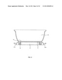
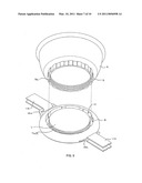
[0020]FIG. 1 is a perspective schematic illustration of an embodiment of an anti-spill vessel in accordance with the invention;
[0021]FIG. 2 is a cross-sectional schematic illustration of the anti-spill vessel of FIG. 1, taken along line A-A;
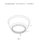
[0022]FIG. 3 is a perspective schematic illustration of a receptacle of the anti-spill vessel of FIG. 1;
[0023]FIG. 4 is a schematic illustration of a bottom of the receptacle of FIG. 3;
[0024]FIG. 5 is a cross-sectional illustration of the receptacle of FIG. 3, taken along line B-B in FIG. 4;
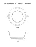
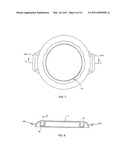
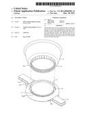
[0025]FIG. 6 is a perspective schematic illustration of a base of the anti-spill vessel of FIG. 1;
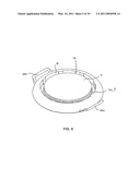
[0026]FIG. 7 is a schematic illustration of a top of the base as shown in FIG. 6;
[0027]FIG. 8 is a cross-sectional illustration of the base of FIG. 6, taken along line C-C in FIG. 7;
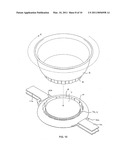
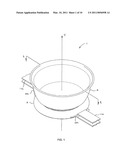
[0028]FIG. 9 is an exploded schematic illustration of the anti-spill vessel of FIG. 1;
[0029]FIG. 10 is an exploded schematic illustration of the anti-spill vessel of FIG. 1, showing the way to connect the receptacle to the base;
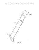
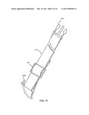
[0030]FIG. 11 is a schematic illustration of an elongate pliable member connected with a male part of a fastener; and
[0031]FIG. 12 is a schematic illustration of an elongate pliable member connected with female part of a fastener.
DETAILED DESCRIPTION OF THE INVENTION
[0032]Referring to FIGS. 1 to 12 of the drawings, there is shown an anti-spill vessel 1 embodying the invention, which has a receptacle in the form of a bowl 2 mounted on a generally flat circular base 3. The base 3 is releasably held onto a table, such as the table of a high chair, by means of a pair of Nylon belts 11a, 11b to prevent the bowl 2 from spilling or slipping off. The vessel 1 is particularly suitable for use by kids and young children learning to feed themselves.
[0033]The bowl 2 is firmly attached to the base 3 using a releasable screw-fit attachment. The bowl 2 has a bottom 6 and a flat cylindrical seat 5 lying directly on the underside of the bottom 6. The seat 5 has a screw-threaded internal wall 5a which forms a first portion of the screw-fit attachment. The seat 5 is threaded internally such that the screw threads are concealed.
[0034]The base 3 has a flat cylindrical central platform 7. The platform 7 has an externally screw-threaded peripheral wall 7a which forms a second portion of the screw-fit attachment. The base 3 has a circular groove 10 that runs around the platform 7. The groove 10 is conformed to accommodate the seat 5, that is by having the same shape and a slightly larger size. The groove 10 has an inner wall 9, which is provided by the peripheral wall 7a of the platform 7, and an outer wall 8 which conceals the screw threads on the inner wall 9.
[0035]With matching dimensions the seat 5 can fit on and around the platform 7. The screw threads on the wall 7a are engageable with the screw threads 5a in the seat 5, such that the bowl 2 and the base 3 can be screwingly connected together through relative rotation about their common vertical central axis Y.
[0036]The base 3 has a considerably larger diameter than the seat 5. It offers a wider bottom/seat for the bowl 2 when the bowl 2 is attached to the base 3, such that the bowl 2 can stand more stably. Even without the belts 11a, 11b, the bowl 2 is less likely to spill when it is used with the base 3.
[0037]The base 3 has a pair of loops 12a, 12b on its opposite left and right sides and along its periphery. The two belts 11a, 11b are connected to the base 3 through the loops 12a, 12b. Each of the belts 11a, 11b runs through a respective loop 12a, 12b and has its free ends connected with a male or female part 13a, 13b of a fastener, such as a snap-fit buckle 13. The belts 11a, 11b extend from opposite sides of the base 3 for fastening upon the table surface to thereby releasably connect the base 3 onto the table.
[0038]In operation, the belts 11a, 11b are wrapped around the table, with the male and female parts 13a, 13b of the buckle 13 then snapped together to close and fasten the belts 11a, 11b around the table, whereby the base 3 is connected to and retained on the table. The base 3 may stay on the table for as long as required, ready for use with the bowl 2 at any time.
[0039]The bowl 2 may be placed co-axially on to the base 3. By turning the bowl 2 clock-wise in direction X, the seat 5 is screwed into the groove 10. The bowl 2 should be turned until it stops to ensure that it firmly attached to the base 3. The seat 5 is concealed in the groove 10 to give an overall neat appearance.
[0040]To release the bowl 2, it should be turned anti-clockwise and lifted from the base 3. To release the base 3 from the table, the buckle parts 13a, 13b are slid apart to release the belts 11a, 11b from the table.
[0041]The belt 11a is fitted with a buckle 14 for adjusting its length such that the two belts 11a, 11b together can fit around all possible variations in design or nature of the table, for connection therewith.
[0042]The bowl 2 may be used with or without the base 3.
[0043]The foregoing description of the invention has been presented for purposes of illustration and description. It is not intended to be exhaustive or to limit the invention to the precise form disclosed, and other modifications and variations may be possible in light of the above description. The embodiment was chosen and described in order to best explain the principles of the invention and its practical application to thereby enable others skilled in the art to best utilize the invention in various embodiments and various modifications as are suited to the particular use contemplated. It is intended that the appended claims be construed to include other alternative embodiments of the invention except insofar as limited by the prior art.
[0044]For example, the bowl and the base are attached together by screw-fit attachment. In an alternative embodiment, the attachment may be effected through the use of a bayonet joint or a snap-fit connection.
[0045]For example, the fastener closing the belts is a buckle in the describe embodiment. In an alternative embodiment, the fastener may be implemented using Velcro loop-and-hoop fasteners.
[0046]As a further example, the belts are connected to the base through the use of a pair of loops. In a different embodiment, there is only one belt which is connected to the base through a flat passage at the bottom of the base.
User Contributions:
comments("1"); ?> comment_form("1"); ?>Inventors list |
Agents list |
Assignees list |
List by place |
Classification tree browser |
Top 100 Inventors |
Top 100 Agents |
Top 100 Assignees |
Usenet FAQ Index |
Documents |
Other FAQs |
User Contributions:
Comment about this patent or add new information about this topic:
| People who visited this patent also read: | |
| Patent application number | Title |
|---|---|
| 20140145677 | APPARATUS FOR TRANSFERRING ENERGY USING POWER ELECTRONICS AND MACHINE INDUCTANCE AND METHOD OF MANUFACTURING SAME |
| 20140145676 | MOUNTING SYSTEM FOR CHARGING EQUIPMENT |
| 20140145675 | SEMICONDUCTOR INTEGRATED CIRCUIT AND OPERATION METHOD OF THE SAME |
| 20140145674 | WIRELESS CHARGING APPARATUS AND ELECTRONIC APPARATUS INCLUDING THE SAME |
| 20140145673 | System for Simultaneously Charging Multiple Portable Electronic Devices |
Images included with this patent application:
 |  |
 |  |
 |  |
 |  |
 |  |
 |
| Similar patent applications: | |
| Date | Title |
|---|---|
| 2010-06-17 | Readily cleanable spill-resistant drinking vessel and valve |
| 2010-08-12 | Vented non-spill fuel cap assembly |
| 2010-11-18 | Self regulating vent for a paint supply vessel |
| 2009-02-26 | Seamless multi-section pressure vessel |
| 2010-08-26 | Headspace sealing and displacement method for removal of vacuum pressure |
| New patent applications in this class: | |
| Date | Title |
|---|---|
| 2016-12-29 | Anchoring device with directional release and attachment capability and protection against inadvertent release |
| 2016-09-01 | Decorative holder for serving/catering trays and tins |
| 2016-05-05 | Plate with retaining structure |
| 2016-04-21 | Food plate |
| 2016-03-31 | Food tray and lid apparatus |
| Top Inventors for class "Receptacles" | |
| Rank | Inventor's name |
|---|---|
| 1 | Daniel Lee Bizzell |
| 2 | Frank Yang |
| 3 | Terry Vovan |
| 4 | William P. Apps |
| 5 | Lowell L. Wood, Jr. |