Patent application title: COOLING SYSTEM AND ELECTRONIC DEVICE USING THE SAME
Inventors:
Zhi-Bin Guan (Tu-Cheng, TW)
Zhi-Bin Guan (Tu-Cheng, TW)
Assignees:
HON HAI PRECISION INDUSTRY CO., LTD.
IPC8 Class: AH05K720FI
USPC Class:
361692
Class name: Fluid air plural openings
Publication date: 2011-02-24
Patent application number: 20110043997
a system air intake, a system air outlet, a fan,
and a noise-reducing outlet. The fan includes a fan intake, and a fan
outlet. The fan drives airflow, from the system air intake through the
fan intake, the fan outlet, and the system air outlet. The noise-reducing
outlet is located adjacent to the fan outlet. When the airflow exits
through the fan outlet, a portion of the airflow exits through the
noise-reducing outlet.Claims:
1. A cooling system comprising:a system air intake;a system air outlet;a
fan comprising a fan intake, and a fan outlet, wherein the fan drives
airflow, from the system air intake, through the fan intake, the fan
outlet, and the system air outlet; anda noise-reducing outlet located
adjacent to the fan outlet, wherein when the airflow flows through the
fan outlet, a portion of the airflow exits through the noise-reducing
outlet.
2. The cooling system of claim 1, wherein the noise-reducing outlet is located between the fan outlet and the system air outlet.
3. The cooling system of claim 2, wherein airflow through the noise-reducing outlet is perpendicular to the airflow out through the system air outlet.
4. A cooling system comprising:a system air intake;a system air outlet;a plurality of fans set abreast, each comprising a fan intake facing the system air intake, and a fan outlet facing the system air outlet, wherein the plurality of fans drive airflow, from the system intake, through the fan intakes, the fan outlets, and the system air outlet; anda plurality of noise-reducing outlets each located adjacent to the fan outlet of a corresponding fan, wherein airflow through the fan outlets comprises a portion exiting through the plurality of noise-reducing outlets.
5. The cooling system of claim 4, wherein the system air intake is opposite to the system air outlet.
6. The cooling system of claim 4, wherein airflow out through the plurality of noise-reducing outlets is perpendicular to the airflow out through the system air outlet.
7. An electronic device comprising:a base comprising a bottom board, a front board extending from a front end of the bottom board, and a rear board extending from a rear end of the bottom board and opposite to the front board, wherein a system air intake is defined in the rear board, and a system air outlet is defined in the front board;a fan mounted in the base and comprising a fan intake facing the system air intake, and a fan outlet facing the system air outlet; anda top board mounted on the base and opposite to the bottom board;wherein a first noise-reducing outlet is defined in one of the bottom board and the top board, adjacent to the fan outlet.
8. The electronic device of claim 7, wherein the first noise-reducing outlet is defined in the top board.
9. The electronic device of claim 8, wherein the first noise-reducing outlet comprises a plurality of holes defined in the top board arranged in a line parallel to the front board and the rear board.
10. The electronic device of claim 9, wherein the fan is located between the system fan intake and the first noise-reducing outlet.
11. The electronic device of claim 10, wherein a second noise-reducing outlet is defined in the bottom board, aligning with the first noise-reducing outlet.
12. The electronic device of claim 8, further comprising a guide duct mounted in the base, wherein the guide duct is located between the fan outlet and the system air outlet, the guide duct comprises an intake directly connected with the fan outlet, and a top wall, a hole is defined in the top wall, adjacent to the fan and communicating with the intake of the guide duct.Description:
BACKGROUND
[0001]1. Technical Field
[0002]The present disclosure relates to a cooling system and an electronic device using the cooling system.
[0003]2. Description of Related Art
[0004]In order to reduce noise, rigid specifications for sound quality have been enacted in industry. In those specifications, loudness, tonality, and modulation strength are all important measurable parameters.
[0005]In an electronic device, such as a computer, a fan is commonly employed for dissipating heat. The fan drives the airflow to dissipate heat, however, aerodynamic noise is correspondingly generated, creating health hazards and impairing communications. Modulation strength is a major parameter of aerodynamic noise.
BRIEF DESCRIPTION OF THE DRAWINGS
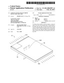
[0006]FIG. 1 is an isometric view of a first embodiment of an electronic device.
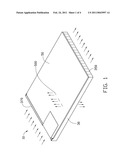
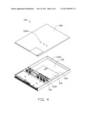
[0007]FIG. 2 is an exploded, isometric view of the electronic device in FIG. 1
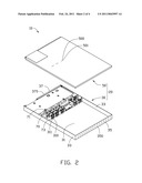
[0008]FIG. 3 is an exploded, isometric view of a second embodiment of an electronic device.
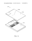
[0009]FIG. 4 is an exploded, isometric view of a third embodiment of an electronic device.
DETAILED DESCRIPTION
[0010]Referring to FIGS. 1 and 2, a first embodiment of an electronic device 10 includes a shell 20, and three fans 70 mounted in the shell 20.
[0011]The shell 20 includes a base 30, and a top board 50 removably mounted thereon. The base 30 includes a bottom board 31, two sideboards 33 extending perpendicular upward from opposite sides of the bottom board 31, and a front board 35 and a rear board 37 extending perpendicular upward from opposite ends of the bottom board 31 and between the sideboards 33. A plurality of holes (not shown) is defined in the rear board 37, to form a system air intake 370. A plurality of holes is defined in the front board 35, to form a system air outlet 350. Three first noise-reducing outlets 310 are defined in the bottom board 31. Each first noise-reducing outlet 310 includes five round first holes 311 defined in the bottom board 31. The first holes 311 are arranged in a line parallel to the front board 35 and the rear board 37. The top board 50 is opposite to the bottom board 31. The top board 50 defines three second noise-reducing outlets 500. Each second noise-reducing outlet 500 includes five round second holes 501 defined in the top board 50. The second holes 501 are arranged in a line, parallel to the front board 35 and the rear board 37. When the top board 50 is mounted on the base 30, the second noise-reducing outlets 500 are aligned with the first noise-reducing outlets 310, respectively.
[0012]The fans 70 are mounted abreast in the base 30. Each fan 70 includes a fan intake 71, and a fan outlet 73 opposite to the fan intake 71. The fans 70 are mounted between the first noise-reducing outlets 310 and the system air intake 370. The fan intakes 71 face the system air intake 370. The fan outlets 73 face the system air outlet 350. The fan outlets 73 are close and adjacent to the first noise-reducing outlets 310, respectively.
[0013]In use, the fans 70 drive airflow into the electronic device 10 through the system air intake 370 parallel to the bottom board 31, and in turn through the fan intakes 71, the fan outlets 73, and the system air outlet 350 to the exterior of the electronic device 10. When the airflow enters the electronic device 10, a portion thereof exits through the first noise-reducing outlets 310 and the second noise-reducing outlets 500 to the exterior of the electronic device 10 perpendicular to the bottom board 31.
[0014]The fan generates a pressure gradient in the electronic device 10, degrading from the system air intake 370 to the system air outlet 350. Furthermore, the change of the pressure gradient is greatest at the fan outlets 73, which is a main contributor to aerodynamic noise. Thus, the first noise-reducing outlets 310 and the second noise-reducing outlets 500 exhaust a portion of the airflow at the fan outlets 73 to the exterior of the electronic device 10, reducing the change of pressure gradient at the fan outlets 73, and, correspondingly, aerodynamic noise.
[0015]It is noted that in other embodiments, the number of fans 70 may be adjusted according to actual need. Furthermore, the number, the shape and/or arrangement of the first holes 311 and the second holes 501 of the first noise-reducing outlets 310 and the second noise-reducing outlets 500 may be similarly adjusted while remaining well within the scope of the disclosure.
[0016]Referring to FIG. 3, a second embodiment of an electronic device 10A is shown, differing from the first embodiment in FIG. 1 only in the absence of noise-reducing outlets in the bottom board 31A, with only the top board 50A defining noise-reducing outlets 500A. It can be seen that in other embodiments, the noise-reducing outlets 500A may be replaced to the bottom board 31A and omitted from other areas.
[0017]Referring to FIG. 4, a third embodiment of an electronic device 10B is shown, differing from the second embodiment in FIG. 3 only in that a guide duct 90B is added for guiding the air to help dissipating heat. The guide duct 90B is mounted to the bottom board 31B between the fan outlets of the fans 70B and the system air outlet 350B. An intake of the guide duct 90B is directly connected with the fan outlets of the fans 70B. The guide duct 90B guides airflow towards the system air outlet 350B. A plurality of elongated holes 910B is defined in a top wall 91B of the guide duct 90B, adjacent to the fans 70B and aligned with the noise-reducing outlets 500B in the top board 50B of the electronic device 10B. A portion of the airflow passes through the holes 910B to go through the noise-reducing outlets 500B to the exterior of the electronic device 10B.
[0018]It has been proven in tests that the presence of the noise-reducing outlets 310, 500, 500A, 500B can reduce modulation strength (unit: %) for an average of about 9%, which greatly advances sound quality of the electronic device 10, 10A or 10B.
[0019]Furthermore, the usage of the noise-reducing outlets 310, 500, 500A, 500B can reduce about 2.2 decibels of loudness and about 0.03 tonality unit, which further advances the sound quality.
[0020]It is to be understood, however, that even though numerous characteristics and advantages of the disclosure have been set forth in the foregoing description, together with details of the structure and function of the invention, the disclosure is illustrative only, and changes may be made in detail, especially in matters of shape, size, and arrangement of parts within the principles of the invention to the full extent indicated by the broad general meaning of the terms in which the appended claims are expressed.
Claims:
1. A cooling system comprising:a system air intake;a system air outlet;a
fan comprising a fan intake, and a fan outlet, wherein the fan drives
airflow, from the system air intake, through the fan intake, the fan
outlet, and the system air outlet; anda noise-reducing outlet located
adjacent to the fan outlet, wherein when the airflow flows through the
fan outlet, a portion of the airflow exits through the noise-reducing
outlet.
2. The cooling system of claim 1, wherein the noise-reducing outlet is located between the fan outlet and the system air outlet.
3. The cooling system of claim 2, wherein airflow through the noise-reducing outlet is perpendicular to the airflow out through the system air outlet.
4. A cooling system comprising:a system air intake;a system air outlet;a plurality of fans set abreast, each comprising a fan intake facing the system air intake, and a fan outlet facing the system air outlet, wherein the plurality of fans drive airflow, from the system intake, through the fan intakes, the fan outlets, and the system air outlet; anda plurality of noise-reducing outlets each located adjacent to the fan outlet of a corresponding fan, wherein airflow through the fan outlets comprises a portion exiting through the plurality of noise-reducing outlets.
5. The cooling system of claim 4, wherein the system air intake is opposite to the system air outlet.
6. The cooling system of claim 4, wherein airflow out through the plurality of noise-reducing outlets is perpendicular to the airflow out through the system air outlet.
7. An electronic device comprising:a base comprising a bottom board, a front board extending from a front end of the bottom board, and a rear board extending from a rear end of the bottom board and opposite to the front board, wherein a system air intake is defined in the rear board, and a system air outlet is defined in the front board;a fan mounted in the base and comprising a fan intake facing the system air intake, and a fan outlet facing the system air outlet; anda top board mounted on the base and opposite to the bottom board;wherein a first noise-reducing outlet is defined in one of the bottom board and the top board, adjacent to the fan outlet.
8. The electronic device of claim 7, wherein the first noise-reducing outlet is defined in the top board.
9. The electronic device of claim 8, wherein the first noise-reducing outlet comprises a plurality of holes defined in the top board arranged in a line parallel to the front board and the rear board.
10. The electronic device of claim 9, wherein the fan is located between the system fan intake and the first noise-reducing outlet.
11. The electronic device of claim 10, wherein a second noise-reducing outlet is defined in the bottom board, aligning with the first noise-reducing outlet.
12. The electronic device of claim 8, further comprising a guide duct mounted in the base, wherein the guide duct is located between the fan outlet and the system air outlet, the guide duct comprises an intake directly connected with the fan outlet, and a top wall, a hole is defined in the top wall, adjacent to the fan and communicating with the intake of the guide duct.
Description:
BACKGROUND
[0001]1. Technical Field
[0002]The present disclosure relates to a cooling system and an electronic device using the cooling system.
[0003]2. Description of Related Art
[0004]In order to reduce noise, rigid specifications for sound quality have been enacted in industry. In those specifications, loudness, tonality, and modulation strength are all important measurable parameters.
[0005]In an electronic device, such as a computer, a fan is commonly employed for dissipating heat. The fan drives the airflow to dissipate heat, however, aerodynamic noise is correspondingly generated, creating health hazards and impairing communications. Modulation strength is a major parameter of aerodynamic noise.
BRIEF DESCRIPTION OF THE DRAWINGS
[0006]FIG. 1 is an isometric view of a first embodiment of an electronic device.
[0007]FIG. 2 is an exploded, isometric view of the electronic device in FIG. 1
[0008]FIG. 3 is an exploded, isometric view of a second embodiment of an electronic device.
[0009]FIG. 4 is an exploded, isometric view of a third embodiment of an electronic device.
DETAILED DESCRIPTION
[0010]Referring to FIGS. 1 and 2, a first embodiment of an electronic device 10 includes a shell 20, and three fans 70 mounted in the shell 20.
[0011]The shell 20 includes a base 30, and a top board 50 removably mounted thereon. The base 30 includes a bottom board 31, two sideboards 33 extending perpendicular upward from opposite sides of the bottom board 31, and a front board 35 and a rear board 37 extending perpendicular upward from opposite ends of the bottom board 31 and between the sideboards 33. A plurality of holes (not shown) is defined in the rear board 37, to form a system air intake 370. A plurality of holes is defined in the front board 35, to form a system air outlet 350. Three first noise-reducing outlets 310 are defined in the bottom board 31. Each first noise-reducing outlet 310 includes five round first holes 311 defined in the bottom board 31. The first holes 311 are arranged in a line parallel to the front board 35 and the rear board 37. The top board 50 is opposite to the bottom board 31. The top board 50 defines three second noise-reducing outlets 500. Each second noise-reducing outlet 500 includes five round second holes 501 defined in the top board 50. The second holes 501 are arranged in a line, parallel to the front board 35 and the rear board 37. When the top board 50 is mounted on the base 30, the second noise-reducing outlets 500 are aligned with the first noise-reducing outlets 310, respectively.
[0012]The fans 70 are mounted abreast in the base 30. Each fan 70 includes a fan intake 71, and a fan outlet 73 opposite to the fan intake 71. The fans 70 are mounted between the first noise-reducing outlets 310 and the system air intake 370. The fan intakes 71 face the system air intake 370. The fan outlets 73 face the system air outlet 350. The fan outlets 73 are close and adjacent to the first noise-reducing outlets 310, respectively.
[0013]In use, the fans 70 drive airflow into the electronic device 10 through the system air intake 370 parallel to the bottom board 31, and in turn through the fan intakes 71, the fan outlets 73, and the system air outlet 350 to the exterior of the electronic device 10. When the airflow enters the electronic device 10, a portion thereof exits through the first noise-reducing outlets 310 and the second noise-reducing outlets 500 to the exterior of the electronic device 10 perpendicular to the bottom board 31.
[0014]The fan generates a pressure gradient in the electronic device 10, degrading from the system air intake 370 to the system air outlet 350. Furthermore, the change of the pressure gradient is greatest at the fan outlets 73, which is a main contributor to aerodynamic noise. Thus, the first noise-reducing outlets 310 and the second noise-reducing outlets 500 exhaust a portion of the airflow at the fan outlets 73 to the exterior of the electronic device 10, reducing the change of pressure gradient at the fan outlets 73, and, correspondingly, aerodynamic noise.
[0015]It is noted that in other embodiments, the number of fans 70 may be adjusted according to actual need. Furthermore, the number, the shape and/or arrangement of the first holes 311 and the second holes 501 of the first noise-reducing outlets 310 and the second noise-reducing outlets 500 may be similarly adjusted while remaining well within the scope of the disclosure.
[0016]Referring to FIG. 3, a second embodiment of an electronic device 10A is shown, differing from the first embodiment in FIG. 1 only in the absence of noise-reducing outlets in the bottom board 31A, with only the top board 50A defining noise-reducing outlets 500A. It can be seen that in other embodiments, the noise-reducing outlets 500A may be replaced to the bottom board 31A and omitted from other areas.
[0017]Referring to FIG. 4, a third embodiment of an electronic device 10B is shown, differing from the second embodiment in FIG. 3 only in that a guide duct 90B is added for guiding the air to help dissipating heat. The guide duct 90B is mounted to the bottom board 31B between the fan outlets of the fans 70B and the system air outlet 350B. An intake of the guide duct 90B is directly connected with the fan outlets of the fans 70B. The guide duct 90B guides airflow towards the system air outlet 350B. A plurality of elongated holes 910B is defined in a top wall 91B of the guide duct 90B, adjacent to the fans 70B and aligned with the noise-reducing outlets 500B in the top board 50B of the electronic device 10B. A portion of the airflow passes through the holes 910B to go through the noise-reducing outlets 500B to the exterior of the electronic device 10B.
[0018]It has been proven in tests that the presence of the noise-reducing outlets 310, 500, 500A, 500B can reduce modulation strength (unit: %) for an average of about 9%, which greatly advances sound quality of the electronic device 10, 10A or 10B.
[0019]Furthermore, the usage of the noise-reducing outlets 310, 500, 500A, 500B can reduce about 2.2 decibels of loudness and about 0.03 tonality unit, which further advances the sound quality.
[0020]It is to be understood, however, that even though numerous characteristics and advantages of the disclosure have been set forth in the foregoing description, together with details of the structure and function of the invention, the disclosure is illustrative only, and changes may be made in detail, especially in matters of shape, size, and arrangement of parts within the principles of the invention to the full extent indicated by the broad general meaning of the terms in which the appended claims are expressed.
User Contributions:
Comment about this patent or add new information about this topic:
| People who visited this patent also read: | |
| Patent application number | Title |
|---|---|
| 20110044883 | METHOD OF PURIFYING GYPSUM |
| 20110044882 | METHOD OF MAKING HIGH PURITY LITHIUM HYDROXIDE AND HYDROCHLORIC ACID |
| 20110044881 | Method For The Catalytic Extraction Of Coal |
| 20110044880 | METHOD AND FACILITY FOR RECOVERING CO2 GAS IN CEMENT MANUFACTURING FACILITY |
| 20110044879 | PROCESS FOR THE TREATMENT AND PURIFICATION OF DANGEROUS WASTES CONTAINING AMMONIUM SALTS, PARTICULARLY AMMONIUM CHLORIDE, DERIVED FROM PHARMACEUTICAL AND CHEMICAL TECHNOLOGIES |
Images included with this patent application:
 |  |
 |  |
 |
| Similar patent applications: | |
| Date | Title |
|---|---|
| 2012-02-09 | Stand fixing mechanism and electronic device using the same |
| 2012-02-02 | Housing and electronic device using the same |
| 2012-01-26 | Shell and electronic device using the same |
| 2012-02-02 | Axial fan and electronic device including the same |
| 2011-12-29 | Hinge and an electronic device with the same |
| New patent applications in this class: | |
| Date | Title |
|---|---|
| 2019-05-16 | Electronic device |
| 2016-07-07 | Display device |
| 2016-06-30 | Heat dissipation device and electronic device |
| 2016-06-16 | Cooling architecture for a chassis with orthogonal connector system |
| 2016-06-09 | Thermal module and electronic device having the thermal module |
| New patent applications from these inventors: | |
| Date | Title |
|---|---|
| 2014-02-06 | Airflow guiding member and electronic device having the airflow guiding member |
| 2014-01-02 | Electronic device incorporating fan module |
| 2013-09-05 | Cooling system |
| 2013-01-24 | All-in-one computer |
| 2012-06-28 | Heat dissipation device |
| Top Inventors for class "Electricity: electrical systems and devices" | |
| Rank | Inventor's name |
|---|---|
| 1 | Zheng-Heng Sun |
| 2 | Levi A. Campbell |
| 3 | Li-Ping Chen |
| 4 | Robert E. Simons |
| 5 | Richard C. Chu |