Patent application title: SEAT TUBE OF A BICYCLE
Inventors:
Peng-Yu Tseng (Taipei, TW)
IPC8 Class: AB62K1936FI
USPC Class:
2485031
Class name: Hold-down vehicle-mounted; for vehicle appurtenance for seat
Publication date: 2011-02-24
Patent application number: 20110042543
has a tubular body and a tightening block. The
tubular body has an insertion hole and a stationary block. The insertion
hole is defined in the tubular body and has an inner surface and a
tightening recess. The inner surface is formed in the tubular body. The
tightening recess is defined in the inner surface. The stationary block
is embedded in the tightening recess and has an oblique surface and a
fastener hole. The fastener hole is defined in the oblique surface. The
tightening block is mounted slidably on the oblique surface and has a
tightening surface, a through hole and a fastener. The tightening surface
is shaped to correspond to the inner surface. The through hole is defined
through the tightening block. The fastener is mounted through the through
hole and engages the fastener hole.Claims:
1. A seat tube of a bicycle comprising:a tubular body havinga top end;an
insertion hole axially defined in the top end of the tubular body and
having an inner surface formed in the insertion hole;a tightening recess
defined in the inner surface at the top end of the tubular body and
havingan opening formed on the top end of the tubular body;a stationary
block embedded in the tightening recess and havinga top;an inner end
shaped corresponding to the inner surface, facing the insertion hole and
having a thickness;an outer end havinga thickness larger than that of the
inner end;an oblique surface defined in the top of the stationary block;a
fastener hole defined in the oblique surface;a tightening block embedded
in the tightening recess, mounted slidably on the stationary block,
shaped corresponding to the tightening recess and havinga sliding surface
shaped obliquely, abutting and mounted slidably on the oblique surface of
the stationary block;a tightening surface shaped corresponding to the
inner surface;a through hole defined through the tightening block;a
fastener mounted through the through hole and engaging the fastener hole
of the stationary block and havinga fastener head abutting against the
sliding block.
2. The seat tube of a bicycle as claimed in claim 1, wherein the tightening recess has a bottom end, and the stationary block is formed on the bottom end of the tightening recess.
3. The seat tube of a bicycle as claimed in claim 1, wherein the insertion hole is fan-shaped and hastwo sides;a V-shaped surface formed on one of the sides of the insertion hole; andthe inner surface is curved, is formed on the other side of the insertion hole and is opposite to the V-shaped surface.
4. The seat tube of a bicycle as claimed in claim 2, whereinthe insertion hole is fan-shaped and hastwo sides;a V-shaped surface formed on one of the sides of the insertion hole; andthe inner surface is curved, is formed on the other side of the insertion hole and is opposite to the V-shaped surface.Description:
BACKGROUND OF THE INVENTION
[0001]1. Field of the Invention
[0002]The present invention relates to a seat tube of a bicycle, and more particularly to a seat tube having a device for adjusting a height of a saddle of a bicycle.
[0003]2. Description of Related Art
[0004]A seat post is connected between a seat tube and a saddle, so a height of the saddle can be adjusted by sliding the seat post relative to the seat tube.
[0005]In order to hold the seat post in position relative to the seat tube, the seat tube has a top end, two fastening rings and a slit. The fastening rings protrude from the top end of the seat tube. The slit is defined in the top end of the seat tube between the fastening rings. When fasteners are tightened against the fastening rings, the slit is narrowed to hold the seat post in position.
[0006]However, with the fastening rings and the fasteners protruding from the seat post, users are easily injured by the fastening rings and fasteners.
[0007]To overcome the shortcomings, the present invention tends to provide a seat tube of a bicycle to mitigate or obviate the aforementioned problems.
SUMMARY OF THE INVENTION
[0008]A seat tube of a bicycle has a tubular body and a tightening block. The tubular body has an insertion hole and a stationary block. The insertion hole is defined in the tubular body and has an inner surface and a tightening recess. The inner surface is formed in the tubular body. The tightening recess is defined in the inner surface. The stationary block is embedded in the tightening recess and has an oblique surface and a fastener hole. The fastener hole is defined in the oblique surface. The tightening block is mounted slidably on the oblique surface and has a tightening surface, a through hole and a fastener. The tightening surface is shaped to correspond to the inner surface of the tubular body. The through hole is defined through the tightening block. The fastener is mounted through the through hole engages the fastener hole. Therefore, the stationary block and the tightening block are concealed in the tightening recess for improved safety and aesthetic appearance.
[0009]Other objects, advantages and novel features of the invention will become more apparent from the following detailed description when taken in conjunction with the accompanying drawings.
BRIEF DESCRIPTION OF THE DRAWINGS
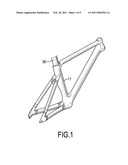
[0010]FIG. 1 is a perspective view of a bicycle frame with a first embodiment of a seat tube in accordance with the present invention;
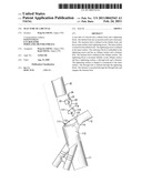
[0011]FIG. 2 is an enlarged partially exploded perspective view of the seat tube in FIG. 1;
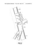
[0012]FIG. 3 is an enlarged side view in partial section of the seat tube in FIG. 1;
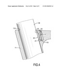
[0013]FIG. 4 is an enlarged operational side view in partial section of the seat tube in FIG. 1; and
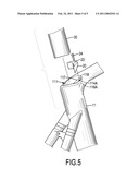
[0014]FIG. 5 is a partially exploded perspective view of a bicycle frame with a second embodiment of a seat tube in accordance with the present invention.
DETAILED DESCRIPTION OF PREFERRED EMBODIMENT
[0015]With reference to FIGS. 1 and 2, a seat tube of a bicycle in accordance with the present invention comprises a tubular body (11) and a tightening block (20). The tubular body (11) has a top end, an insertion hole (111) and a stationary block (116). The insertion hole (111) may be square or preferably fan-shaped, is axially defined in the top end of the tubular body (11) and has two sides, a V-shaped surface (112), an inner surface (113) and a tightening recess (114). The V-shaped surface (112) is formed on one of the sides of the insertion hole (111). The inner surface (113) may be curved, is formed on the other sides of the insertion hole (111) and is opposite to the V-shaped surface (112). The tightening recess (114) is defined in the inner surface (113) at the top end of the tubular body (11) and has an opening (115). The opening (115) is formed on the top end of the tubular body (11). The stationary block (116) is embedded in the tightening recess (114), may be welded, adhered or formed in tightening recess (114) and has an inner end, an outer end, an oblique surface (117) and a fastener hole (118). With reference to FIG. 5, the stationary block (116A) may be formed integrally on a bottom end of the tightening recess (114A) opposite to the opening. The inner end shape to correspond to the inner surface (113), may be concave, faces the insertion hole (111) and has a thickness. The outer end is opposite to the inner end and has a thickness larger than that of the inner end. The oblique surface (117) is defined in the top of the stationary block (116). The fastener hole (118) is defined in the oblique surface (117). The tightening block (20) is embedded in the tightening recess (114), is mounted slidably on the stationary block (116) and has a sliding surface (21), a tightening surface (22), a through hole (23) and a fastener (24). The sliding surface (21) is shaped obliquely, abuts with and is mounted slidably on the oblique surface (117) of the stationary block (116). The tightening surface (22) is concave is shaped to correspond to the inner surface (113). The through hole (23) is defined through the tightening block (20). The fastener (24) is mounted through the through hole (23) and engages the fastener hole (118) of the stationary block (116) and has a fastener head abutting against the sliding block (20). In the preferred embodiment, the through hole (23) may be elongated or have a diameter larger than that of the fastener (24) to allow the tightening block (20) move relative to the fastener (24).
[0016]With reference to FIGS. 1 to 4, a seat post (30) having a cross section corresponding to that of the insertion hole (111) is inserted into the insertion hole (111) of the tubular body (11) via the top end of the tubular body (11). With the non-circular cross section of the insertion hole (111), the seat post (30) in the insertion hole (111) is not rotatable. Then, a height of the seat post (30) is adjusted to a desired level, and the fastener (24) is rotated to make the fastener head abutting against and pressing onto the tightening block (20), Consequently, the tightening block (20) is moved to abut and tighten the seat post (30) by the tightening surface (22) with the oblique sliding surface (21) sliding along the oblique surface (117) of the stationary block (116). Therefore, the seat post (30) can be held stably in position relative to the tubular body (11). Additionally, because the stationary block (116) and the tightening block (20) are concealed in the tightening recess (114), injuries are prevented to improve safety as well as aesthetic appearance.
[0017]Even though numerous characteristics and advantages of the present invention have been set forth in the foregoing description, together with details of the structure and function of the invention, the disclosure is illustrative only, and changes may be made in detail, especially in matters of shape, size, and arrangement of parts within the principles of the invention to the full extent indicated by the broad general meaning of the terms in which the appended claims are expressed.
Claims:
1. A seat tube of a bicycle comprising:a tubular body havinga top end;an
insertion hole axially defined in the top end of the tubular body and
having an inner surface formed in the insertion hole;a tightening recess
defined in the inner surface at the top end of the tubular body and
havingan opening formed on the top end of the tubular body;a stationary
block embedded in the tightening recess and havinga top;an inner end
shaped corresponding to the inner surface, facing the insertion hole and
having a thickness;an outer end havinga thickness larger than that of the
inner end;an oblique surface defined in the top of the stationary block;a
fastener hole defined in the oblique surface;a tightening block embedded
in the tightening recess, mounted slidably on the stationary block,
shaped corresponding to the tightening recess and havinga sliding surface
shaped obliquely, abutting and mounted slidably on the oblique surface of
the stationary block;a tightening surface shaped corresponding to the
inner surface;a through hole defined through the tightening block;a
fastener mounted through the through hole and engaging the fastener hole
of the stationary block and havinga fastener head abutting against the
sliding block.
2. The seat tube of a bicycle as claimed in claim 1, wherein the tightening recess has a bottom end, and the stationary block is formed on the bottom end of the tightening recess.
3. The seat tube of a bicycle as claimed in claim 1, wherein the insertion hole is fan-shaped and hastwo sides;a V-shaped surface formed on one of the sides of the insertion hole; andthe inner surface is curved, is formed on the other side of the insertion hole and is opposite to the V-shaped surface.
4. The seat tube of a bicycle as claimed in claim 2, whereinthe insertion hole is fan-shaped and hastwo sides;a V-shaped surface formed on one of the sides of the insertion hole; andthe inner surface is curved, is formed on the other side of the insertion hole and is opposite to the V-shaped surface.
Description:
BACKGROUND OF THE INVENTION
[0001]1. Field of the Invention
[0002]The present invention relates to a seat tube of a bicycle, and more particularly to a seat tube having a device for adjusting a height of a saddle of a bicycle.
[0003]2. Description of Related Art
[0004]A seat post is connected between a seat tube and a saddle, so a height of the saddle can be adjusted by sliding the seat post relative to the seat tube.
[0005]In order to hold the seat post in position relative to the seat tube, the seat tube has a top end, two fastening rings and a slit. The fastening rings protrude from the top end of the seat tube. The slit is defined in the top end of the seat tube between the fastening rings. When fasteners are tightened against the fastening rings, the slit is narrowed to hold the seat post in position.
[0006]However, with the fastening rings and the fasteners protruding from the seat post, users are easily injured by the fastening rings and fasteners.
[0007]To overcome the shortcomings, the present invention tends to provide a seat tube of a bicycle to mitigate or obviate the aforementioned problems.
SUMMARY OF THE INVENTION
[0008]A seat tube of a bicycle has a tubular body and a tightening block. The tubular body has an insertion hole and a stationary block. The insertion hole is defined in the tubular body and has an inner surface and a tightening recess. The inner surface is formed in the tubular body. The tightening recess is defined in the inner surface. The stationary block is embedded in the tightening recess and has an oblique surface and a fastener hole. The fastener hole is defined in the oblique surface. The tightening block is mounted slidably on the oblique surface and has a tightening surface, a through hole and a fastener. The tightening surface is shaped to correspond to the inner surface of the tubular body. The through hole is defined through the tightening block. The fastener is mounted through the through hole engages the fastener hole. Therefore, the stationary block and the tightening block are concealed in the tightening recess for improved safety and aesthetic appearance.
[0009]Other objects, advantages and novel features of the invention will become more apparent from the following detailed description when taken in conjunction with the accompanying drawings.
BRIEF DESCRIPTION OF THE DRAWINGS
[0010]FIG. 1 is a perspective view of a bicycle frame with a first embodiment of a seat tube in accordance with the present invention;
[0011]FIG. 2 is an enlarged partially exploded perspective view of the seat tube in FIG. 1;
[0012]FIG. 3 is an enlarged side view in partial section of the seat tube in FIG. 1;
[0013]FIG. 4 is an enlarged operational side view in partial section of the seat tube in FIG. 1; and
[0014]FIG. 5 is a partially exploded perspective view of a bicycle frame with a second embodiment of a seat tube in accordance with the present invention.
DETAILED DESCRIPTION OF PREFERRED EMBODIMENT
[0015]With reference to FIGS. 1 and 2, a seat tube of a bicycle in accordance with the present invention comprises a tubular body (11) and a tightening block (20). The tubular body (11) has a top end, an insertion hole (111) and a stationary block (116). The insertion hole (111) may be square or preferably fan-shaped, is axially defined in the top end of the tubular body (11) and has two sides, a V-shaped surface (112), an inner surface (113) and a tightening recess (114). The V-shaped surface (112) is formed on one of the sides of the insertion hole (111). The inner surface (113) may be curved, is formed on the other sides of the insertion hole (111) and is opposite to the V-shaped surface (112). The tightening recess (114) is defined in the inner surface (113) at the top end of the tubular body (11) and has an opening (115). The opening (115) is formed on the top end of the tubular body (11). The stationary block (116) is embedded in the tightening recess (114), may be welded, adhered or formed in tightening recess (114) and has an inner end, an outer end, an oblique surface (117) and a fastener hole (118). With reference to FIG. 5, the stationary block (116A) may be formed integrally on a bottom end of the tightening recess (114A) opposite to the opening. The inner end shape to correspond to the inner surface (113), may be concave, faces the insertion hole (111) and has a thickness. The outer end is opposite to the inner end and has a thickness larger than that of the inner end. The oblique surface (117) is defined in the top of the stationary block (116). The fastener hole (118) is defined in the oblique surface (117). The tightening block (20) is embedded in the tightening recess (114), is mounted slidably on the stationary block (116) and has a sliding surface (21), a tightening surface (22), a through hole (23) and a fastener (24). The sliding surface (21) is shaped obliquely, abuts with and is mounted slidably on the oblique surface (117) of the stationary block (116). The tightening surface (22) is concave is shaped to correspond to the inner surface (113). The through hole (23) is defined through the tightening block (20). The fastener (24) is mounted through the through hole (23) and engages the fastener hole (118) of the stationary block (116) and has a fastener head abutting against the sliding block (20). In the preferred embodiment, the through hole (23) may be elongated or have a diameter larger than that of the fastener (24) to allow the tightening block (20) move relative to the fastener (24).
[0016]With reference to FIGS. 1 to 4, a seat post (30) having a cross section corresponding to that of the insertion hole (111) is inserted into the insertion hole (111) of the tubular body (11) via the top end of the tubular body (11). With the non-circular cross section of the insertion hole (111), the seat post (30) in the insertion hole (111) is not rotatable. Then, a height of the seat post (30) is adjusted to a desired level, and the fastener (24) is rotated to make the fastener head abutting against and pressing onto the tightening block (20), Consequently, the tightening block (20) is moved to abut and tighten the seat post (30) by the tightening surface (22) with the oblique sliding surface (21) sliding along the oblique surface (117) of the stationary block (116). Therefore, the seat post (30) can be held stably in position relative to the tubular body (11). Additionally, because the stationary block (116) and the tightening block (20) are concealed in the tightening recess (114), injuries are prevented to improve safety as well as aesthetic appearance.
[0017]Even though numerous characteristics and advantages of the present invention have been set forth in the foregoing description, together with details of the structure and function of the invention, the disclosure is illustrative only, and changes may be made in detail, especially in matters of shape, size, and arrangement of parts within the principles of the invention to the full extent indicated by the broad general meaning of the terms in which the appended claims are expressed.
User Contributions:
Comment about this patent or add new information about this topic:
| People who visited this patent also read: | |
| Patent application number | Title |
|---|---|
| 20110042127 | ELECTRONIC COMPONENT AND MANUFACTURING METHOD THEREOF |
Images included with this patent application:
 |  |
 |  |
 |  |
| Similar patent applications: | |
| Date | Title |
|---|---|
| 2013-04-11 | Fastening device on the underbody of a motor vehicle |
| 2008-11-06 | Derailleurbracket for a bicycle |
| 2011-03-10 | Slide structure of vehicle seat |
| 2011-06-23 | Seat rail of motorcycle |
| 2012-03-29 | Seat track mechanism for vehicle |
| New patent applications in this class: | |
| Date | Title |
|---|---|
| 2016-07-07 | Fitting for fixing an object on a rail |
| 2016-06-30 | Track and seat adapter for positioning and locking wheelchairs and transit seats |
| 2016-06-30 | Track and seat adapter for positioning and locking wheelchairs and transit seats |
| 2016-05-12 | Seat rail for supporting seats in an aircraft and a method of manufacturing a seat rail |
| 2015-12-31 | Locking device |
| New patent applications from these inventors: | |
| Date | Title |
|---|---|
| 2010-09-23 | Holding assembly for a seat of a bicycle |
| 2009-12-03 | Securing device for a bicycle front fork |
| Top Inventors for class "Supports" | |
| Rank | Inventor's name |
|---|---|
| 1 | Jeffrey D. Carnevali |
| 2 | Yun-Lung Chen |
| 3 | Wen-Tang Peng |
| 4 | Zheng-Heng Sun |
| 5 | Zhan-Yang Li |