Patent application title: METHOD OF ATTACHING A CELL-OF-INTEREST TO A MICROTUBE
Inventors:
Jonathan Charles Kuhn (Haifa, IL)
Eyal Zussman (Haifa, IL)
Michal Green (Haifa, IL)
Shiri Klein (Tel-Aviv, IL)
Assignees:
Technion Research & Development Foundation Ltd.
IPC8 Class: AC12Q102FI
USPC Class:
435 29
Class name: Chemistry: molecular biology and microbiology measuring or testing process involving enzymes or micro-organisms; composition or test strip therefore; processes of forming such composition or test strip involving viable micro-organism
Publication date: 2011-02-17
Patent application number: 20110039296
Inventors list |
Agents list |
Assignees list |
List by place |
Classification tree browser |
Top 100 Inventors |
Top 100 Agents |
Top 100 Assignees |
Usenet FAQ Index |
Documents |
Other FAQs |
Patent application title: METHOD OF ATTACHING A CELL-OF-INTEREST TO A MICROTUBE
Inventors:
Jonathan Charles Kuhn
Eyal Zussman
Michal Green
Shiri Klein
Agents:
MARTIN D. MOYNIHAN d/b/a PRTSI, INC.
Assignees:
Origin: ARLINGTON, VA US
IPC8 Class: AC12Q102FI
USPC Class:
Publication date: 02/17/2011
Patent application number: 20110039296
Abstract:
A method of attaching a cell or a membrane-coated particle-of-interest to
a microtube is provided. The method comprising: co-electrospinning two
polymeric solutions through co-axial capillaries, wherein a first
polymeric solution of the two polymeric solutions is for forming a shell
of the microtube and a second polymeric solution of the two polymeric
solutions is for forming a coat over an internal surface of the shell,
the first polymeric solution is selected solidifying faster than the
second polymeric solution and a solvent of the second polymeric solution
is selected incapable of dissolving the first polymeric solution and
wherein the second polymeric solution comprises the cell or the
membrane-coated particle-of-interest, thereby attaching the cell or the
membrane-coated panicle-of-interest to the microtube. Also provided are
microtubes with attached, entrapped or encapsulated cells or
membrane-coated particles and methods of using same.Claims:
1. A method of attaching a cell or a membrane-coated particle-of-interest
to a microtube, the method comprising: co-electrospinning two polymeric
solutions through co-axial capillaries, wherein a first polymeric
solution of said two polymeric solutions is for forming a shell of the
microtube and a second polymeric solution of said two polymeric solutions
is for forming a coat over an internal surface of said shell, said first
polymeric solution is selected solidifying faster than said second
polymeric solution and a solvent of said second polymeric solution is
selected incapable of dissolving said first polymeric solution and
wherein said second polymeric solution comprises the cell or the
membrane-coated particle-of-interest, thereby attaching the cell or the
membrane-coated particle-of-interest to the microtube.
2. A microtube comprising an electrospun shell, an electrospun coat over an internal surface of said shell and a cell or a membrane-coated particle-of-interest attached to the microtube.
3. The microtube of claim 2, wherein said electrospun shell is formed of a first polymeric solution and said electrospun coat is formed of a second polymeric solution.
4. The microtube of claim 3, wherein said first polymeric solution solidifies faster than said second polymeric solution.
5. The microtube of claim 3, wherein a solvent of said second polymeric solution is incapable of dissolving said first polymeric solution.
6. The microtube of claim 2, wherein said electrospun shell comprises a polymer selected from the group consisting of poly(e-caprolactone) (PCL), polyamide, poly(siloxane), poly(silicone), poly(ethylene), poly(vinyl pyrrolidone), poly(2-hydroxy ethylmethacrylate), poly(N-vinyl pyrrolidone), poly(methyl methacrylate), poly(vinyl alcohol), poly(acrylic acid), poly(vinyl acetate), polyacrylamide, poly(ethylene-co-vinyl acetate), poly(ethylene glycol), poly(methacrylic acid), polylactide, polyglycolide, poly(lactide-coglycolide), polyanhydride, polyorthoester, poly(carbonate), poly(acrylo nitrile), poly(ethylene oxide), polyaniline, polyvinyl carbazole, polystyrene, poly(vinyl phenol), polyhydroxyacid, poly(caprolactone), polyanhydride, polyhydroxyalkanoate, polyurethane, collagen, albumin, alginate, chitosan, starch, hyaluronic acid, and whereas said electrospun coat comprises a polymer selected from the group consisting of poly(acrylic acid), poly(vinyl acetate), polyacrylamide, poly(ethylene-co-vinyl acetate), poly(ethylene glycol), poly(methacrylic acid), polylactide polyglycolide, poly(lactide-coglycolide), polyanhydride, polyorthoester, poly(carbonate), poly(ethylene oxide), polyaniline, polyvinyl carbazole, polystyrene, poly(vinyl phenol), polyhydroxyacid, alginate, starch, hyaluronic acid.
7. The microtube of claim 3, wherein a solvent of said first polymeric solution evaporates faster than a solvent of said second polymeric solution.
8. (canceled)
9. The microtube of claim 3, wherein a solvent of said second polymeric solution is capable of evaporating through said internal surface of said shell.
10. The microtube of claim 3, wherein said second polymeric solution is capable of wetting said internal surface of said shell.
11. The microtube of claim 2, wherein a thickness of said shell is from about 100 nm to about 20 micrometer.
12. The microtube of claim 2, wherein an internal diameter of the microtube is from about 50 nm to about 20 micrometer.
13. The microtube of claim 3, wherein said first and said second polymeric solutions are selected from the group consisting of: 10% poly(e-caprolactone) (PCL) in chloroform (CHCl3) and dimethylforamide (DMF) (80:20 by weight) as said first polymeric solution and 4% poly(ethylene oxide) (PEO) in water (H2O) and ethanol (60:40 by weight) as said second polymeric solution, 10% PCL in CHCl3 and DMF (80:20 by weight) as said first polymeric solution and 6% PEO in H2O and ethanol (60:40 by weight) as said second polymeric solution, 9% PCL in CHCl3 and DMF (90:10 by weight) as said first polymeric solution and 7% PEO in H2O as said second polymeric solution, 10% PCL in CHCl3 and DMF (80:20 by weight) as said first polymeric solution and 9% poly(vinyl alcohol) (PVA) in water and ethanol (50:50 by weight) as said second polymeric solution, and 10% PCL in CHCl3 and DMF (90:10 by weight) as the first polymeric solution and 4% (by weight) PEO in ethanol:H2O (26:74 by weight) as a second polymeric solution.
14. The microtube of claim 2, wherein said microtube is filled with a liquid.
15. The microtube of claim 3, wherein said first and said second polymeric solutions are biocompatible.
16. The microtube of claim 2, wherein said cell or said membrane-coated particle-of-interest is attached to said coat over said internal surface of said shell.
17. The microtube of claim 2, wherein said cell or said membrane-coated particle-of-interest is attached to said shell of the microtube.
18. (canceled)
19. The microtube of claim 2, wherein said shell comprises pores.
20. The microtube of claim 2, wherein said shell prevents diffusion of the cell or the membrane-coated particle-of-interest therethrough.
21. The microtube of claim 2, wherein said cell comprises a prokaryotic cell.
22. The microtube of claim 2, wherein said cell comprises a cell wall.
23. A method of bioremediation, the method comprising contacting a solution containing a contaminant with the microtube of claim 2, wherein said cell, a portion of said cell or said membrane-coated particle-of-interest is capable of degrading or assimilating said contaminant.
24. (canceled)
25. A method of depleting a molecule from a solution, comprising contacting the solution with the microtube of claim 2, wherein the molecule is capable of binding to or being processed by said cell or said membrane-coated particle-of-interest, thereby depleting the molecule from the solution.
26. The method of claim 23, further comprising collecting said solution following said contacting.
27. A method of isolating a molecule from a solution, comprising:(a) contacting the solution with the microtube of claim 2, under conditions which allow binding of the molecule to said cell or said membrane-coated particle-of-interest, and;(b) eluting the molecule from the microtube;thereby isolating the molecule from the solution.
28. A method of detecting a presence of a molecule in a sample, comprising:(a) contacting the sample with the microtube of claim 2, wherein said cell or said membrane-coated particle-of-interest is capable of binding to or processing said molecule, and;(b) detecting said binding or said processing;thereby detecting the presence of the molecule in the sample.
Description:
RELATED APPLICATIONS
[0001]This application claims priority from U.S. Provisional Application Nos. 61/064,210, 61/064,206 and 61/064,204 filed on Feb. 21, 2008.
[0002]The teachings of PCT/IB2007/054001 are incorporated herein by reference.
[0003]The contents of all of the above documents are incorporated by reference as if fully set forth herein.
FIELD AND BACKGROUND OF THE INVENTION
[0004]The present invention, in some embodiments thereof, relates to a method of attaching a cell or a membrane-coated particle-of-interest to a microtube and, more particularly, but not exclusively, to electrospun microtubes which include cells or membrane-coated particles attached, entrapped or encapsulated therein which can be used in various applications such as water purification, detoxification, mineral enrichment, tissue grafts and cell-based therapy.
[0005]Water purification usually entails the removal of toxic chemicals such as mercury, mercurial compounds, and cadmium or elements such as toluene, chloroform, benzene, pesticides and herbicides. Interestingly, although these organic compounds are not found in nature and result from modern industry and motor vehicles, certain bacterial strains have evolved mechanisms for degrading them while utilizing their carbon and nitrogen atoms.
[0006]For example, Pseudomonads can be used to degrade toluene (Moat and Foster, 1995), benzene, phenol, naphthalene (Doelle, 1969) and certain hydrocarbons from oil (van der Linden et al., 1965). In addition, atrazine, a commonly used toxic herbicide that enters the water supply, can be detoxified to ammonia and carbon di-oxide via a dechlorinization reaction mediated by Pseudomonas ADP. Thus, bioparticles of Pseudomonas ADP grown on granulated active carbon were shown capable of degrading atrazine in water (Herzberg et al., 2006). However, since the granulated active carbon particles are only effective for a limited time, a carbon source (citrate) must be added to the water as it enters the purification column, which may be associated with the growth of other bacterial species and increases the costs of the purification process.
[0007]Another serious problem which occurs in some water systems is the presence of toxic heavy metals such as cadmium and mercury. Several bacterial strains such as Chromobacterium violaceum, Pseudomonas maltophila, Pseudomonas aeruginosa, Spirulina planensis, Staphylococcus aureus, Bacillus cereus, Bacillus subtilis and Escherichia coli have been found capable of removing metal contamination, destroying the toxic complex containing the metallic ions (e.g., cadmium and tellurium) or recovering valuable metals such as platinum and palladium, gold and silver from the water. For example, certain bacteria have been used to form nanoparticles of valuable metals (Brayner et al., 2007).
[0008]Nanofibers and polymeric nanofibers in particular can be produced by the electrospinning process (Reneker D H., et al., 2006; Ramakrishna S., et al., 2005; Li D, et al., 2004; PCT WO 2006/106506 to Zussman, E., et al.). Sun and co-workers (Sun Z, et al., 2003) describe the production of core-shell nanofibers (i.e., filled fibers) by co-electrospinning of two polymeric solutions using a spinneret with two co-axial capillaries. US patent application No. 20060119015 to Wehrspohn R., et al. describes the production of hollow fibers by introducing a liquid containing a polymer to a porous template material, and removal of the template following polymer solidification. PCT/IB2007/054001 to Zussman, E., et al. (which is fully incorporated herein by reference) discloses methods of producing electrospun microtubes (i.e., hollow fibers) which can be further filled with liquids and be used as microfluidics.
[0009]Salalha W., et al., 2006, describe the encapsulation of whole bacterial cells and complex bacterial viruses in electrospun single-layer fibers, in which the entrapped cells or viruses retained both physiological activity and some of their viability, even after storing the dry electrospun mats for a number of months.
SUMMARY OF THE INVENTION
[0010]According to an aspect of some embodiments of the present invention there is provided a method of attaching a cell or a membrane-coated particle-of-interest to a microtube, the method comprising: co-electrospinning two polymeric solutions through co-axial capillaries, wherein a first polymeric solution of the two polymeric solutions is for forming a shell of the microtube and a second polymeric solution of the two polymeric solutions is for forming a coat over an internal surface of the shell, the first polymeric solution is selected solidifying faster than the second polymeric solution and a solvent of the second polymeric solution is selected incapable of dissolving the first polymeric solution and wherein the second polymeric solution comprises the cell or the membrane-coated particle-of-interest, thereby attaching the cell or the membrane-coated particle-of-interest to the microtube.
[0011]According to an aspect of some embodiments of the present invention there is provided a microtube comprising an electrospun shell, an electrospun coat over an internal surface of the shell and a cell or a membrane-coated particle-of-interest attached to the microtube.
[0012]According to an aspect of some embodiments of the present invention there is provided a method of bioremediation, the method comprising contacting a solution containing a contaminant with the microtube of some embodiments of the invention, wherein the cell, a portion of the cell or the membrane-coated particle-of-interest is capable of degrading or assimilating the contaminant.
[0013]According to an aspect of some embodiments of the present invention there is provided a method of depleting a molecule from a solution, comprising contacting the solution with the microtube of some embodiments of the invention, wherein the molecule is capable of binding to or being processed by the cell or the membrane-coated particle-of-interest, thereby depleting the molecule from the solution.
[0014]According to an aspect of some embodiments of the present invention there is provided a method of isolating a molecule from a solution, comprising: (a) contacting the solution with the microtube of some embodiments of the invention under conditions which allow binding of the molecule to the cell or the membrane-coated particle-of-interest, and; (b) eluting the molecule from the microtube; thereby isolating the molecule from the solution.
[0015]According to an aspect of some embodiments of the present invention there is provided a method of detecting a presence of a molecule in a sample, comprising: (a) contacting the sample with the microtube of some embodiments of the invention, wherein the cell or the membrane-coated particle-of-interest is capable of binding to or processing the molecule, and; (b) detecting the binding or the processing; thereby detecting the presence of the molecule in the sample.
[0016]According to some embodiments of the invention, the electrospun shell is formed of a first polymeric solution and the electrospun coat is formed of a second polymeric solution.
[0017]According to some embodiments of the invention, the first polymeric solution solidifies faster than the second polymeric solution.
[0018]According to some embodiments of the invention, a solvent of the second polymeric solution is incapable of dissolving the first polymeric solution.
[0019]According to some embodiments of the invention, the electrospun shell comprises a polymer selected from the group consisting of poly(e-caprolactone) (PCL), polyamide, poly(siloxane), poly(silicone), poly(ethylene), poly(vinyl pyrrolidone), poly(2-hydroxy ethylmethacrylate), poly(N-vinyl pyrrolidone), poly(methyl methacrylate), poly(vinyl alcohol), poly(acrylic acid), poly(vinyl acetate), polyacrylamide, poly(ethylene-co-vinyl acetate), poly(ethylene glycol), poly(methacrylic acid), polylactide, polyglycolide, poly(lactide-coglycolide), polyanhydride, polyorthoester, poly(carbonate), poly(acrylo nitrile), poly(ethylene oxide), polyaniline, polyvinyl carbazole, polystyrene, poly(vinyl phenol), polyhydroxyacid, poly(caprolactone), polyanhydride, polyhydroxyalkanoate, polyurethane, collagen, albumin, alginate, chitosan, starch and hyaluronic acid, and whereas the electrospun coat comprises a polymer selected from the group consisting of poly(acrylic acid), poly(vinyl acetate), polyacrylamide, poly(ethylene-co-vinyl acetate), poly(ethylene glycol), poly(methacrylic acid), polylactide polyglycolide, poly(lactide-coglycolide), polyanhydride, polyorthoester, poly(carbonate), poly(ethylene oxide), polyaniline, polyvinyl carbazole, polystyrene, poly(vinyl phenol), polyhydroxyacid, alginate, starch and hyaluronic acid.
[0020]According to some embodiments of the invention, a solvent of the first polymeric solution evaporates faster than a solvent of the second polymeric solution.
[0021]According to some embodiments of the invention, the electrospinning is effected using a rotating collector.
[0022]According to some embodiments of the invention, the solvent of the second polymeric solution is capable of evaporating through the internal surface of the shell.
[0023]According to some embodiments of the invention, the second polymeric solution is capable of wetting the internal surface of the shell.
[0024]According to some embodiments of the invention, a thickness of the shell is from about 100 nm to about 20 micrometer.
[0025]According to some embodiments of the invention, an internal diameter of the microtube is from about 50 nm to about 20 micrometer.
[0026]According to some embodiments of the invention, the first and the second polymeric solutions are selected from the group consisting of: 10% poly(e-caprolactone) (PCL) in chloroform (CHCl3) and dimethylforamide (DMF) (80:20 by weight) as the first polymeric solution and 4% poly(ethylene oxide) (PEO) in water (H2O) and ethanol (60:40 by weight) as the second polymeric solution, 10% PCL in CHCl3 and DMF (80:20 by weight) as the first polymeric solution and 6% PEO in H2O and ethanol (60:40 by weight) as the second polymeric solution, 9% PCL in CHCl3 and DMF (90:10 by weight) as the first polymeric solution and 7% PEO in H2O as the second polymeric solution, 10% PCL in CHCl3 and DMF (80:20 by weight) as the first polymeric solution and 9% poly(vinyl alcohol) (PVA) in water and ethanol (50:50 by weight) as the second polymeric solution, and 10% PCL in CHCl3 and DMF (90:10 by weight) as the first polymeric solution and 4% (w/w) PEO in ethanol:H2O (26:74 by weight) as a second polymeric solution.
[0027]According to some embodiments of the invention, the microtube is filled with a liquid.
[0028]According to some embodiments of the invention, the first and the second polymeric solutions are biocompatible.
[0029]According to some embodiments of the invention, the cell or the membrane-coated particle-of-interest is attached to the coat over the internal surface of the shell.
[0030]According to some embodiments of the invention, the cell or the membrane-coated particle-of-interest is attached to the shell of the microtube.
[0031]According to some embodiments of the invention, the first polymeric solution comprises polyethylene glycol (PEG).
[0032]According to some embodiments of the invention, the shell comprises pores.
[0033]According to some embodiments of the invention, the shell prevents diffusion of the cell or the membrane-coated particle-of-interest therethrough.
[0034]According to some embodiments of the invention, the cell comprises a prokaryotic cell.
[0035]According to some embodiments of the invention, the cell comprises a cell wall.
[0036]According to some embodiments of the invention, the contaminant comprises atrazine.
[0037]According to some embodiments of the invention, the method further comprising collecting said solution following the contacting.
[0038]Unless otherwise defined, all technical and/or scientific terms used herein have the same meaning as commonly understood by one of ordinary skill in the art to which the invention pertains. Although methods and materials similar or equivalent to those described herein can be used in the practice or testing of embodiments of the invention, exemplary methods and/or materials are described below. In case of conflict, the patent specification, including definitions, will control. In addition, the materials, methods, and examples are illustrative only and are not intended to be necessarily limiting.
BRIEF DESCRIPTION OF THE DRAWINGS
[0039]Some embodiments of the invention are herein described, by way of example only, with reference to the accompanying drawings. With specific reference now to the drawings in detail, it is stressed that the particulars shown are by way of example and for purposes of illustrative discussion of embodiments of the invention. In this regard, the description taken with the drawings makes apparent to those skilled in the art how embodiments of the invention may be practiced.
[0040]In the drawings:
[0041]FIGS. 1A-B are images depicting high resolution scanning electron microscope (HRSEM) micrographs of the microtubes according to an embodiment of the invention which are attached to cells of microorganisms such that the cells are entrapped therein. Electrospinning was performed using a first polymeric solution (for forming the shell) which consisted of 9% [weight/weight (w/w)] polycaprolactone (PCL) dissolved in chloroform/DMSO [9:1 (w/w)]; and a second polymeric solution (for forming the coat over the internal surface of the shell) which consisted of 8% poly(ethylene oxide) (PEO) in water (w/w). FIG. 1A--Magnification of 5000×; FIG. 1B--Magnification of 10,000×.
[0042]FIG. 2 is a microscopic image of Pseudomonas putida bacterial cells transformed with the DsRed expression vector encoding the red fluorescent protein [GenBank Accession No. Q9U6Y8 (SEQ ID NO:7)] and entrapped within a microtube of an embodiment of the invention. A microtube was formed by co-electrospinning of the two polymeric solutions: 9% (w/w) polycaprolactone (PCL) dissolved in chloroform/DMSO [9:1 (w/w)] as a first polymeric solution (for forming the shell); and 8% poly(ethylene oxide) (PEO) in water (w/w) as second polymeric solution (for forming the coat over the internal surface of the shell) which also included 100 μl of Pseudomonas putida bacterial cells (at a concentration of 109 cells/ml). Detection of the bacterial cells within the microtube was performed using a fluorescence microscope. Red fluorescence of the red fluorescent protein (RFP) encoded by the DsRed expression vector was visualized at a wavelength of 359 nm for excitation and examining emitted light at a wavelength of 361 nm. Magnification: 200×; Size bar: 20 μm.
[0043]FIGS. 3A-B are schematic illustrations depicting the encapsulation of bacteria (FIG. 3A) and the growth of entrapped bacteria (FIG. 3B) within the microtube of some embodiments of the invention. FIG. 3A--A microtube is formed from two polymeric solutions, the first one, for forming the shell is insoluble in water, and the second one, for forming the coat over the internal surface of the shell is soluble in water (see for example, the description of solutions with FIG. 2, hereinabove). Following microtube formation, the microtube can be filled with an aqueous solution (e.g., water or phosphate buffer) by simply exposing the microtube to an aqueous solution (e.g., by immersing the microtube in the aqueous solution). The aqueous solution dissolves some of the polymer of the inner layer (the coat over the internal surface of the shell) which is mixed with the bacterial cells and the bacteria are released to the internal volume of the microtube. The bacteria (red circles) reside within the soluble layer. FIG. 3B--The bacteria (red circles) can proliferate within the soluble layer of the microtube when supplied with appropriate nutrients.
[0044]FIG. 4 is a schematic illustration of a bioremediation system generated according to some embodiments of the invention. System 300 comprises conduit [220, e.g., part of an aqueous system, can be a plastic or metal (e.g., copper) pipe/tube] having borders (100) includes microtube (230) with shell borders (120) and entrapped bacterial cells (210, red). For purification (e.g., detoxification of water), a liquid (e.g., drinking water) containing molecule (150, blue) flows within the conduit. Pores (180) within the microtube shell enable the diffusion of molecule (150) through the microtube shell to the microtube lumen (140) containing bacterial cells (210). Cells (210) interact with molecule (150) and reaction product (160, green) diffuses out of the microtube outside of the microtube lumen (140) through the microtube shell pores (180).
[0045]FIG. 5 depicts the degradation of atrazine by Pseudomonas ADP bacterial cells which are attached to (entrapped or encapsulated within) the microtube of the invention. Atrazine is degraded by the Pseudomonas ADP endogenous enzymes: atrazine chlorohydrolase, e.g., GenBank Accession No. NP--862474 (SEQ ID NO:1) encoded by the gene atzA, hydroxyatrazine hydrolase, e.g., GenBank Accession No. NP 862481 (SEQ ID NO:2) encoded by atzB, N-isopropylammelide isopropylamino hydrolase, e.g., GenBank Accession No. NP 862508 (SEQ ID NO:3) encoded by atzC, cyanuric acid amidohydrolase, e.g., GenBank Accession No. NP--862537 (SEQ ID NO:4) encoded by atzD, biuret hydrolase, e.g., GenBank Accession No. NP--862538 (SEQ ID NO:5) encoded by atzE and allophanate hydrolase, e.g., GenBank Accession No. AAK50333 (SEQ ID NO:6) encoded by atzF.
DESCRIPTION OF SPECIFIC EMBODIMENTS OF THE INVENTION
[0046]The present invention, in some embodiments thereof, relates to methods of attaching a cell or a membrane-coated particle to a microtube and, more particularly, but not exclusively, to microtubes with cells or membrane-coated particles attached, entrapped or encapsulated therein and uses thereof in various purification, bioremediation, isolation, detection, and therapeutic applications.
[0047]Before explaining at least one embodiment of the invention in detail, it is to be understood that the invention is not necessarily limited in its application to the details set forth in the following description or exemplified by the Examples. The invention is capable of other embodiments or of being practiced or carried out in various ways.
[0048]While reducing the present invention to practice, the present inventors have devised a method of attaching a cell or a membrane-coated particle to a microtube, to thereby obtain attached, entrapped or encapsulated cells or membrane-coated particles within the microtube.
[0049]Thus, as described in Example 1 of the Examples section which follows, the present inventors were capable of attaching cells (e.g., bacterial cells) to a microtube. In addition as shown in FIG. 2, cells attached within electrospun microtubes remained intact and viable. Moreover, as shown in Tables 4 and 5 and described in Example 2 of the Examples section which follows, the attached cells preserved their catalytic activity following the electrospinning process and were capable of degrading atrazine from a solution. These results suggest the use of the microtubes of some embodiments of the invention in various applications such a bioremediation of solutions (flow-through applications) and soils, purification, detoxification, and synthesis.
[0050]According to one aspect of the invention there is provided a method of attaching a cell or a membrane-coated particle-of-interest to a microtube, the method comprising: co-electrospinning two polymeric solutions through co-axial capillaries, wherein a first polymeric solution of the two polymeric solutions is for forming a shell of the microtube and a second polymeric solution of the two polymeric solutions is for forming a coat over an internal surface of the shell, the first polymeric solution is selected solidifying faster than the second polymeric solution and a solvent of the second polymeric solution is selected incapable of dissolving the first polymeric solution and wherein the second polymeric solution comprises the cell or the membrane-coated particle-of-interest, thereby attaching the cell or the membrane-coated particle-of-interest to the microtube.
[0051]As used herein the term "microtube" refers to a hollow tube having an inner diameter from about 50 nm to about 50 μm and an outer diameter from about 0.5 μm to about 100 μm.
[0052]According to some embodiments of the invention the inner diameter of the microtube shell of the invention can vary from about 100 nm to about 20 μm, e.g., from about 200 nm to about 10 μm, e.g., from about 500 nm to about 5 μm, e.g., from about 1 μm to about 5 μm, e.g., about 3 μm.
[0053]According to some embodiments of the invention the thickness of the microtube shell of the invention can vary from a few nanometers to several micrometers, such as from about 100 nm to about 20 μm, e.g., from about 200 nm to about 10 μm, from about 100 nm to about 5 μm, from about 100 nm to about 1 μm, e.g., about 500 nm.
[0054]According to some embodiments of the invention, the microtube may have a length which is from about 0.1 millimeter (mm) to about 20 centimeter (cm), e.g., from about 1-20 cm, e.g., from about 5-10 cm.
[0055]As used herein the term "cell" refers to a eukaryotic or prokaryotic cell.
[0056]According to some embodiments of the invention, the cell-of-interest comprises a cell wall. Non-limiting examples of cells which comprise a cell wall and which can be attached to the microtube of the invention include plant cells, bacteria (e.g., Gram positive and Gram negative bacteria), archaea, protozoa, fungi, and algae.
[0057]According to some embodiments of the invention, the cell-of-interest comprises a dermis (e.g., insect cells).
[0058]According to some embodiments of the invention, the cell has a diameter from about 500 nanometers to about 30 microns, e.g., from about 1-10 microns.
[0059]According to some embodiments of the invention, the cell has a diameter from about 1-2 microns.
[0060]The cell-of-interest which is attached to the microtube may have an activity (e.g., a catalytic activity or a binding activity) which is beneficial (e.g., expression of specific enzymes, e.g., atrazine-degrading enzyme, binding to a specific substrate via a cell receptor or via interaction with a molecule present in the cells, e.g., a DNA, RNA or protein). According to some embodiments of the invention, the cell is genetically modified to express a gene or a protein-of-interest (e.g., a mutant form which is capable of degrading a substrate with an improved catalytic activity as compared to a wild-type form; a specific label, e.g., a green fluorescent protein). Genetic modification can be done using known recombinant DNA technology and include, but not limited to, mutant isolation, know-out or knock-in mutagenesis, site-directed mutagenesis, gene silencing (e.g., siRNA, Ribozyme, DNAzyme, antisense) and gene overexpression (e.g., by transfection with an expression vector).
[0061]As used herein the phrase "membrane-coated particle" refers to a lipid membrane coated particle. The membrane may enable passage of molecules (e.g., organic and inorganic molecules, polymeric molecules) therethrough.
[0062]The membrane may be a naturally occurring membrane (e.g., a cell membrane), a portion of a naturally occurring membrane (e.g., a vesicle), an artificial membrane formed of natural membrane components (e.g., a liposome with a lipid bilayer), and/or an artificial membrane formed of non-natural components such as a polymer, a surfactant [e.g., dioleoylphosphatidylethanolamine (DOPE)], a ceramic, a glass and/or a metal.
[0063]Liposomes include emulsions, foams, micelles, insoluble monolayers, liquid crystals, phospholipid dispersions, lamellar layers and the like. The liposomes may be prepared by any of the known methods in the art [Monkkonen, J. et al., 1994, J. Drug Target, 2:299-308; Monkkonen, J. et al., 1993, Calcif. Tissue Int., 53:139-145; Lasic D D., Liposomes Technology Inc., Elsevier, 1993, 63-105. (chapter 3); Winterhalter M, Lasic D D, Chem Phys Lipids, 1993 September; 64(1-3):35-43]. The liposomes may be positively charged, neutral or negatively charged. The liposomes may have a single lipid layer or may be multilamellar. If the therapeutic agent is hydrophilic, its delivery may be further improved using large unilamellar vesicles because of their greater internal volume. Conversely, if the therapeutic agent is hydrophobic, its delivery may be further improved using multilamellar vesicles. Alternatively, the therapeutic agent (e.g. oligonucleotide) may not be able to penetrate the lipid bilayer and consequently would remain adsorbed to the liposome surface. In this case, increasing the surface area of the liposome may further improve delivery of the therapeutic agent. The liposomes can be non-toxic liposomes such as, for example, those prepared from phosphatidyl-choline phosphoglycerol, and cholesterol. The diameter of the liposomes used can range from 0.1-1.0 microns.
[0064]The particle may comprise an atom, an isotope, a molecule (e.g., a bio-molecule such as an amino acid, a nucleic acid, a polypeptide, a DNA or an RNA), a drug, a virus, a portion of a cell (e.g., a cell vesicle, enzymes of a cell), a bead (e.g., a glass bead, a magnetic bead) or any combination thereof, e.g., a magnetic bead conjugated to a molecule such as a polypeptide, a DNA and/or an RNA.
[0065]As used herein the term "attaching" refers to the binding of the cell or the membrane-coated particle-of-interest to the polymer(s) comprised in the microtube of the invention via covalent or non-covalent binding (e.g., via an electrostatic bond, a hydrogen bond, a van-Der Waals interaction) so as to obtain an absorbed, embedded or immobilized cell or membrane-coated particle-of-interest to the microtube of the invention.
[0066]According to some embodiments of the invention, the length (L) of the microtube can be several orders of magnitude higher (e.g., 10 times, 100 times, 1000 times, 10,000 times, e.g., 50,000 times) than the microtube's diameter (D). Accordingly, a cell or a membrane-coated particle-of-interest which is attached to a microtube is referred to as being entrapped or encapsulated within the microtube.
[0067]According to some embodiments of the invention, covalent attachment of the cell or membrane-coated particle can be via functional groups such as SH groups, amino groups, carboxyl groups which are added to the polymer(s) forming the microtube.
[0068]As used herein the phrase "co-electrospinning" refers to a process in which at least two polymeric solutions are electrospun from co-axial capillaries (i.e., at least two capillary dispensers wherein one capillary is placed within the other capillary while sharing a co-axial orientation) forming the spinneret within an electrostatic field in a direction of a collector. The capillary can be, for example, a syringe with a metal needle or a bath provided with one or more capillary apertures from which the polymeric solution can be extruded, e.g., under the action of hydrostatic pressure, mechanical pressure, air pressure and/or high voltage.
[0069]The collector serves for collecting the electrospun element (e.g., the electrospun microtube) thereupon. Such a collector can be a rotating collector or a static (non rotating) collector. When a rotating collector is used, such a collector may have a cylindrical shape (e.g., a drum), however, the rotating collector can be also of a planar geometry (e.g., an horizontal disk). The spinneret is typically connected to a source of high voltage, such as of positive polarity, while the collector is grounded, thus forming an electrostatic field between the dispensing capillary (dispenser) and the collector. Alternatively, the spinneret can be grounded while the collector is connected to a source of high voltage, such as with negative polarity. As will be appreciated by one ordinarily skilled in the art, any of the above configurations establishes motion of a positively charged jet from the spinneret to the collector. Reverse polarity for establishing motions of a negatively charged jet from the spinneret to the collector are also contemplated.
[0070]For electrospinning, the first polymeric solution is injected into the outer capillary of the co-axial capillaries while the second polymeric solution is injected into the inner capillary of the co-axial capillaries. In order to form a microtube (i.e., a hollow structure, as mentioned above), the first polymeric solution (which is for forming the shell of the microtube) solidifies faster than the second polymeric solution (also referred herein as a core polymeric solution, and is for forming a coat over the internal surface of the shell). In addition, the formation of a microtube also requires that the solvent of the second polymeric solution be incapable of dissolving the first polymeric solution.
[0071]The solidification rates of the first and second polymeric solutions are critical for forming the microtube. For example, for a microtube of about 100 μm, the solidification of the first polymer (of the first polymeric solution) can be within about 30 milliseconds (ms) while the solidification of the second polymer (of the second polymeric solution) can be within about 10-20 seconds. The solidification may be a result of polymerization rate and/or evaporation rate.
[0072]According to some embodiments of the invention, the solvent of the first polymeric solution evaporates faster than the solvent of second polymeric solution (e.g., the solvent of the first polymeric solution exhibits a higher vapor pressure than the solvent of the second polymeric solution).
[0073]According to some embodiments of the invention, the rate of evaporation of the solvent of the first polymeric solution is at least about 10 times faster than that of the solvent of the second polymeric solution. The evaporation rate of the solvent of the first polymeric solution can be at least about 100 times faster or at least about 1000 times faster than the evaporation rate of the solvent of second polymeric solution. For example, the evaporation of chloroform is significantly faster than the evaporation of an aqueous solution (water) due to the high vapor pressure at room temperature of the chloroform (195 mmHg) vs. that of the aqueous solution (23.8 mmHg).
[0074]When selecting a solvent of the second polymeric solution which is incapable of dissolving the first polymeric solution (i.e., a non-solvent of the first polymeric solution), the polymer of the first polymeric solution can solidify (e.g., through precipitation) and form a strong microtube shell which does not collapse, and which is characterized by an even thickness. According to some embodiments of the invention, the first polymeric solution (e.g., the solvent of the first polymer) is substantially immiscible in the solvent of the second polymeric solution.
[0075]The solvent of the second polymeric solution may evaporate while the polymer (of the second polymeric solution) forms a thin layer on the internal surface of the shell.
[0076]According to some embodiments of the invention, the solvent of the second polymeric solution is capable of evaporating through the internal surface of the shell.
[0077]The flow rates of the first and second polymeric solutions can determine the microtube outer and inner diameter and thickness of shell. Non-limiting examples are shown in Table 1 hereinbelow.
TABLE-US-00001 TABLE 1 Effect of the flow rates of the two polymeric solutions during electrospinning on microtube diameter and thickness of shell System: First polymeric R solution/ Flow Outer d Second rates Fiber Shell V Electrostatic System polymeric (ml/ radius thickness Voltage field No. solution hr) (μm) (μm) (kV) kV/cm M5 First 4 3.0-4.5 0.5 ± 0.1 8.5 0.43 polymeric solution Second 0.5 polymeric solution M10 First 10 2.3-4.0 1.0 ± 0.1 8 0.5 polymeric solution Second 0.3 polymeric solution M11 First 10 3-6 1.0 ± 0.1 9 0.56 polymeric solution Second 2 polymeric solution Table 1: Electrospinning was performed with the following solutions: First polymeric solution (for forming the shell) was 10% PCL in CHCl3/DMF (8:2 weight/weight); second polymeric solution (for forming the coat) was 4% PEO in H2O/EtOH (6:4, weight/weight). PCL 80K; PEO 600K. The temperature during electrospinning was of 22-26° C. The relative humidity was 58%, 52% and 53% for systems M5, M10 and M11, respectively. The flow rates were measured in milliliter per hour (ml/hr); the outer microtube radius and the shell thickness were measured in microns (μm). The resulting tubes were hollow (good tubes in systems M5 and M11, and mostly good in system M10).
[0078]As used herein the phrase "polymeric solution" refers to a soluble polymer, i.e., a liquid medium containing one or more polymers, co-polymers or blends of polymers dissolved in a solvent. The polymer used by the invention can be a natural, synthetic, biocompatible and/or biodegradable polymer.
[0079]The phrase "synthetic polymer" refers to polymers that are not found in nature, even if the polymers are made from naturally occurring biomaterials. Examples include, but are not limited to, aliphatic polyesters, poly(amino acids), copoly(ether-esters), polyalkylenes, oxalates, polyamides, tyrosine derived polycarbonates, poly(iminocarbonates), polyorthoesters, polyoxaesters, polyamidoesters, polyoxaesters containing amine groups, poly(anhydrides), polyphosphazenes, and combinations thereof.
[0080]Suitable synthetic polymers for use by the invention can also include biosynthetic polymers based on sequences found in naturally occurring proteins such as those of collagen, elastin, thrombin, fibronectin, or mutant or synthetic derivatives thereof or, starches, poly(amino acids), polypropylene fumarate), gelatin, alginate, pectin, fibrin, oxidized cellulose, chitin, chitosan, tropoelastin, hyaluronic acid, polyethylene, polyethylene terephthalate, poly(tetrafluoroethylene), polycarbonate, polypropylene and poly(vinyl alcohol), ribonucleic acids, deoxyribonucleic acids, polypeptides, proteins, polysaccharides, polynucleotides and combinations thereof.
[0081]The phrase "natural polymer" refers to polymers that are naturally occurring. Non-limiting examples of such polymers include, silk, collagen-based materials, chitosan, hyaluronic acid, albumin, fibrinogen, and alginate.
[0082]As used herein, the phrase "co-polymer" refers to a polymer of at least two chemically distinct monomers. Non-limiting examples of co-polymers include, polylactic acid (PLA)-polyethyleneglycol (PEG), polyethylene glycol terephthalate (PEGT)/polybutylene terephthalate (PBT), PLA-polyglycolic acid (PGA), PEG-polycaprolactone (PCL) and PCL-PLA.
[0083]As used herein, the phrase "blends of polymers" refers to the result of mixing two or more polymers together to create a new material with different physical properties.
[0084]The phrase "biocompatible polymer" refers to any polymer (synthetic or natural) which when in contact with cells, tissues or body fluid of an organism does not induce adverse effects such as immunological reactions and/or rejections, cellular death, and the like. A biocompatible polymer can also be a biodegradable polymer.
[0085]According to some embodiments of the invention, the first and the second polymeric solutions are biocompatible.
[0086]Non-limiting examples of biocompatible polymers include polyesters (PE), PCL, calcium sulfate, PLA, PGA, PEG, polyvinyl alcohol, polyvinyl pyrrolidone, polytetrafluoroethylene (PTFE, teflon), polypropylene (PP), polyvinylchloride (PVC), polymethylmethacrylate (PMMA), polyamides, segmented polyurethane, polycarbonate-urethane and thermoplastic polyether urethane, silicone-polyether-urethane, silicone-polycarbonate-urethane collagen, PEG-DMA, alginate, hydroxyapatite and chitosan, blends and copolymers thereof.
[0087]The phrase "biodegradable polymer" refers to a synthetic or natural polymer which can be degraded (i.e., broken down) in a physiological environment such as by proteases or other enzymes produced by living organisms such as bacteria, fungi, plants and animals. Biodegradability depends on the availability of degradation substrates (i.e., biological materials or portion thereof which are part of the polymer), the presence of biodegrading materials (e.g., microorganisms, enzymes, proteins) and the availability of oxygen (for aerobic organisms, microorganisms or portions thereof), lack of oxygen (for anaerobic organisms, microorganisms or portions thereof) and/or other nutrients. Examples of biodegradable polymers/materials include, but are not limited to, collagen (e.g., collagen I or IV), fibrin, hyaluronic acid, polylactic acid (PLA), polyglycolic acid (PGA), polycaprolactone (PCL), polydioxanone (PDO), trimethylene carbonate (TMC), polyethyleneglycol (PEG), collagen, PEG-DMA, alginate, chitosan copolymers or mixtures thereof.
[0088]According to some embodiments, the polymeric solution can be made of one or more polymers, each can be a polymer or a co-polymer such as described hereinabove.
[0089]According to some embodiments of the invention, the polymeric solution is a mixture of at least one biocompatible polymer and a co-polymer (either biodegradable or non-biodegradable).
[0090]According to some embodiments of the invention, the first polymeric solution for forming the shell can be made of a polymer such as poly(e-caprolactone) (PCL), polyamide, poly(siloxane), poly(silicone), poly(ethylene), poly(vinyl pyrrolidone), poly(2-hydroxy ethylmethacrylate), poly(N-vinyl pyrrolidone), poly(methyl methacrylate), poly(vinyl alcohol), poly(acrylic acid), poly(vinyl acetate), polyacrylamide, poly(ethylene-co-vinyl acetate), poly(ethylene glycol), poly(methacrylic acid), polylactide, polyglycolide, poly(lactide-coglycolide), polyanhydride, polyorthoester, poly(carbonate), poly(acrylo nitrile), poly(ethylene oxide), polyaniline, polyvinyl carbazole, polystyrene, poly(vinyl phenol), polyhydroxyacid, poly(caprolactone), polyanhydride, polyhydroxyalkanoate, polyurethane, collagen, albumin, alginate, chitosan, starch, hyaluronic acid, and blends and copolymers thereof.
[0091]According to some embodiments of the invention, the second polymeric solution for forming the coat over the internal surface of the shell can be made of a polymer such as poly(acrylic acid), poly(vinyl acetate), polyacrylamide, poly(ethylene-co-vinyl acetate), poly(ethylene glycol), poly(methacrylic acid), polylactide polyglycolide, poly(lactide-coglycolide), polyanhydride, polyorthoester, poly(carbonate), poly(ethylene oxide), polyaniline, polyvinyl carbazole, polystyrene, poly(vinyl phenol), polyhydroxyacid, alginate, starch, hyaluronic acid, and blends and copolymers thereof.
[0092]During the formation of the microtube shell (e.g., following the solidification of the first polymeric solution) the second polymeric solution flows within the internal surface of the shell.
[0093]According to some embodiments of the invention, the second polymeric solution is selected capable of wetting the internal surface of the shell.
[0094]Various polymeric solutions are capable of wetting other polymeric surfaces (for forming the shell). Following is a non-limiting list of pairs of polymeric solutions in which the second polymeric solution is capable of wetting the internal surface of the shell formed by the first polymeric solution.
TABLE-US-00002 TABLE 2 Pairs of polymeric solutions for producing the microtube of the invention First polymeric solution forming the Second polymeric solution capable of shell wetting the internal surface of the shell 10% poly (e-caprolactone) (PCL); in 4% poly(ethylene oxide) (PEO); in water chloroform (CHCl3) and (H2O) and ethanol (60:40 by weight) dimethylforamide (DMF) (80:20 by weight) Nylon 6,6 in formic acid 7 to 12 wt % 4% poly(ethylene oxide) (PEO); in water (H2O) and ethanol (60:40 by weight) Poly(L-lactide-co-glycolide) (PLGA 4% poly(ethylene oxide) (PEO) in water 10:90) in hexafluroisopropanol (HFIP) (H2O) and ethanol (60:40 by weight) concentrations ranging from 2 to 7 weight % solution. Poly(L-lactide-co-glycolide) (PLGA 4% poly(ethylene oxide) (PEO); in water 15:85) hexafluroisopropanol (HFIP) (H2O) and ethanol (60:40 by weight) concentrations ranging from 2 to 7 weight % solution. poly(lactide-co-glycolide) (PLGA; 4% poly(ethylene oxide) (PEO); in water 1-lactide/glycolide_50/50) (H2O) and ethanol (60:40 by weight) 1,1,1,3,3,3-hexafluoro-2-propanol (HFIP) concentrations ranging from 2 to 7 weight % solution. polyglycolide (PGA) in chloroform 3-10 9% poly(vinyl alcohol) (PVA); in water weight % solution. and ethanol (50:50 by weight) poly(L-lactide) (PLA) in chloroform 3- 9% poly(vinyl alcohol) (PVA); in water 10 weight % solution. and ethanol (50:50 by weight) Segmented polyurethane in DMF and 9% poly(vinyl alcohol) (PVA); in water THF (80:20 by weight) and ethanol (50:50 by weight) Polyurethane in DMF and 9% poly(vinyl alcohol) (PVA); in water tetrahydrofuran, THF (80:20 by weight) and ethanol (50:50 by weight) PLGA (poly lactic-co-glycolic acid); in 9% poly(vinyl alcohol) (PVA); in water chloroform and DMSO (dimethyl and ethanol (50:50 by weight) sulfoxide) in chloroform and DMSO (80:20 by weight). 10% PCL in CHCl3/DMF (80:20 by weight) 6% PEO in H2O/EtOH (60:40 by weight) 9% PCL in CHCl3/DMSO (90:10 by weight) 7% PEO in H2O 10% PCL in CHCl3/DMF (80:20 by weight) 9% PVA in ethanol/water (50:50 by weight) 10% PCL 80 K CHCl3:DMF (90:10 by weight) 4% (w/w) PEO 600 K; in ethanol:H2O (26:74 by weight) 10% PCL 80 K +1% PEG 6 K CHCl3:DMF 4% (w/w) PEO 600 K; in ethanol:H2O (90:10 by weight) (26:74 by weight) Table 2 (cont.). The polymers forming the solutions and the solvents are provided by weight ratios, i.e., a weight/weight (w/w) ratio.
[0095]According to some embodiments of the invention, the first and the second polymeric solutions are selected from the group consisting of: 10% poly(e-caprolactone) (PCL) in chloroform (CHCl3) and dimethylforamide (DMF) (80:20 by weight) as the first polymeric solution and 4% poly(ethylene oxide) (PEO) in water (H2O) and ethanol (60:40 by weight) as the second polymeric solution, 10% PCL in CHCl3 and DMF (80:20 by weight) as the first polymeric solution and 6% PEO in water and ethanol (60:40 by weight) as the second polymeric solution, 9% PCL in CHCl3 and DMF (90:10 by weight) as the first polymeric solution and 7% PEO in water as the second polymeric solution, 10% PCL in CHCl3 and DMF (80:20 by weight) as the first polymeric solution and 9% poly(vinyl alcohol) (PVA) in water and:ethanol (50:50 by weight) as the second polymeric solution and 10% PCL in CHCl3 and DMF (90:10 by weight) as the first polymeric solution and 4% (w/w) PEO in ethanol:water (26:74 by weight) as a second polymeric solution.
[0096]According to some embodiments of the invention, the microtube can be filled with a liquid.
[0097]To enable a flow of a liquid-of-interest within the microtube, i.e., along the coat polymer covering the internal surface of the shell (which originates from the second polymer solution), the surface (thin film) formed by the coat polymer should be designed such that it can be wetted by the liquid-of-interest. The ability to wet (wettability) polymer films by liquids is known in the art. For example, silicone oil or water can wet a surface made of a PEO polymer. The wettability of the coat polymer covering the internal surface of the shell can be controlled (e.g., improved) for example by attaching (e.g., using plasma treatment) functional groups such as hydroxyl groups (OH) which increase the hydrophilicity of the coat [see Thurston R M, Clay J D, Schulte M D, Effect of atmospheric plasma treatment on polymer surface energy and adhesion, Journal of Plastic Film & Sheeting 23 (1): 63-78 JAN 2007; which is incorporated within by reference].
[0098]For certain applications the microtube shell may comprise pores, thus creating a "breathing" tube. Methods of forming "breathing" microtube (i.e., microtubes with pores in the shell thereof) are described in PCT/IB2007/054001 to Zussman E., et al., which is fully incorporated herein by reference. Briefly, "breathing" tubes can be formed by the inclusion of a high percent (e.g., at least 80%) of a volatile component such as tetrahydrofuran (THF), chloroform, acetone, or trifluoroethanol (TFE) in the first polymeric solution forming the shell, and/or by the inclusion of a water-soluble polymer such as polyethylene glycol (PEG) in the first polymeric solution forming the shell so that the first polymeric solution comprises a blend of polymers in which one is water-soluble and the other is water-insoluble (e.g., a blend of PEG and PCL). Alternatively, "breathing" microtubes can be formed by inducing pores in the shell after the completion of the electrospinning process, essentially as described in PCT WO 2006/106506 to the present inventors, which is fully incorporated herein by reference, such as by passing an electrical spark or a heated puncturing element through the electrospun shell, or by using a pulsed or continuous laser beam through the electrospun shell.
[0099]According to some embodiments of the invention, the first polymeric solution comprises PEG for inducing pores in the shell. For example, to generate pores greater (>) than 150 nm in diameter, the first polymeric solution may include about 4% PEG MW 35 kDa. Similarly, to generate pores smaller (<) 150 nm in diameter, the first polymeric solution may include about 2% PEG MW 6 kDa.
[0100]The microtube shell can be designed for selective passage of certain molecules or particles. The passage through the shell pores depends on the size and/or the electrical charge of the molecules/particles with respect to the geometry (length and radius), surface energy, electrical charge of the shell pores, and the viscosity and surface tension of the liquid containing the molecules/particles.
[0101]According to some embodiments of the invention, the porosity [i.e., the ratio of the volume of the shell pores to the volume of the shell mass] and pore size can control the release of the cell or the membrane-coated particle-of-interest from the microtube. For example, a shell with pores larger than 1 μm in diameter (e.g., about 1-2 μm) can enable the release of a cell therethrough. In addition, increased porosity can result in a greater rate of release through the shell pores.
[0102]Alternatively, the microtube shell can be made such that it prevents diffusion or passage of the cell, the membrane-coated particle-of-interest or any molecule therethrough (e.g., substantially devoid of pores, or with pores having a diameter which is smaller than the cell or the membrane-coated particle-of-interest, or which exhibit a geometry which prevents passage of cells or membrane-coated particles therethrough).
[0103]According to some embodiments of the invention, the cell or the membrane-coated particle-of-interest is attached to the polymer of the coat over the internal surface of the shell. For example, as shown in FIG. 2 and described in Example 1 of the Examples section which follows, Pseudomonas putida cells which express the DsRed fluorescent protein were attached to the internal surface of the shell.
[0104]According to some embodiments of the invention, the cell or the membrane-coated particle is attached to the microtube shell.
[0105]According to some embodiments of the invention attachment of the cell (e.g., a eukaryotic cell such as a mammalian cell) or the membrane-coated particle is performed following microtube formation. For example, the microtube can be soaked with a solution containing the cell/membrane-coated particle. The cell/membrane-coated particle can diffuse through the shell pores and enter the inner lumen of the microtube. In addition, the microtube can be covalently attached to the cell/membrane-coated particle (e.g., via SH groups).
[0106]Regardless of the method of production, the present invention provides a microtube which comprises an electrospun shell, an electrospun coat over an internal surface of the shell and a cell or a membrane-coated particle-of-interest attached to the microtube.
[0107]As used herein, the phrase "electrospun shell" refers to a hollow element of a tubular shape, made of one or more polymers, produced by the process of electrospinning as detailed above.
[0108]As used herein the phrase "electrospun coat" refers to a thin layer covering the internal surface of the shell of the microtube of the invention which is made of one or more polymers by the process of electrospinning as detailed above.
[0109]One of ordinary skill in the art will know how to distinguish an electrospun object from objects made by means which do not comprise electrospinning by the high orientation of the macromolecules, the skin (e.g., shell) morphology, and the typical dimensions of the microtube which are unique to electrospinning.
[0110]The microtube of the invention can form an individual (e.g., single or separated) microtube or can form part of a plurality (e.g., an aligned array) of microtubes which can be either connected to each other or separated (as single, not-connected microtubes).
[0111]For the production of a single microtube a fork like clip is attached to the edge of the rotating disk. The disk is rotated for 1-2 seconds and individual microtubes are formed between the sides of the clip. In a similar way individual electrospun fibers were collected [see E. Zussman, M. Burman, A. L. Yarin, R. Khalfin, Y. Cohen, "Tensile Deformation of Electrospun Nylon 6,6 Nanofibers," Journal of Polymer Science Part B: Polymer Physics, 44, 1482-1489, (2006), herein incorporated by reference in its entirety].
[0112]Alternatively, when using a rotating collector, a plurality of microtubes can be formed and collected on the edge of the collector as described elsewhere for electrospun fibers [A. Theron, E. Zussman, A. L. Yarin, "Electrostatic field-assisted alignment of electrospun nanofibers", Nanotechnology J., 12, 3: 384-390, (2001); herein incorporated by reference in its entirety].
[0113]The plurality of microtubes can be arranged on a single layer, or alternatively, the plurality of microtubes define a plurality of layers hence form a three dimensional structure. The microtubes can have a general random orientation, or a preferred orientation, as desired. For example, when the fibers are collected on a cylindrical collector such as a drum, the microtubes can be aligned predominantly axially or predominantly circumferentially. Different layers of the electrospun microtubes can have different orientation characteristics. For example, without limiting the scope of the present invention to any specific ordering or number of layers, the microtubes of a first layer can have a first predominant orientation, the microtubes of a second layer can have a second predominant orientation, and the microtubes of third layer can have general random orientation.
[0114]The microtube of the invention can be available as a dry fibrous mat(s) (e.g., as spun dry microtubes) or as a wetted mat(s) (e.g., following immersing or filling the microtube with a liquid).
[0115]According to some embodiments of the invention, the microtube which is attached to the cell or the membrane-coated particle-of-interest is configured as or in a microfluidics device. "Lab-on-a-chip" is described in a series of review articles [see for example, Craighead, H. "Future lab-on-a-chip technologies for interrogating individual molecules". Nature 442, 387-393 (2006); deMello, A. J. "Control and detection of chemical reactions in microfluidic systems". Nature 442, 394-402 (2006); El-Ali, J., Sorger, P. K. & Jensen, K. F. "Cells on chips". Nature 442, 403-411 (2006); Janasek, D., Franzke, J. & Manz, A. "Scaling and the design of miniaturized chemical-analysis systems". Nature 442, 374-380 (2006); Psaltis, D., Quake, S. R. & Yang, C. H. "Developing optofluidic technology through the fusion of microfluidics and optics". Nature 442, 381-386 (2006); Whitesides, G. M. "The origins and the future of microfluidics". Nature 442, 368-373 (2006); Yager, P. et al. "Microfluidic diagnostic technologies for global public health". Nature 442, 412-418 (2006)] each of which is fully incorporated herein by reference].
[0116]According to some embodiments of the invention, the liquid which fills in, flows in or surrounds the microtube enables the desorption (detachment) of the cell or the membrane-coated particle from the microtube (e.g., from the polymer included in the coat over the internal surface of the shell). According to of some embodiments of the invention the desorption process facilitates the interaction between the entrapped or encapsulated cell/membrane-coated particle with a molecule-of-interest (e.g., a substrate of an enzyme contained within the cell/membrane coated particle). According to some embodiments of the invention, the desorption process enables the flow and/or the release of the cell/membrane-coated particle within and from the microtube.
[0117]The cell or the membrane-coated particle-of-interest which is attached, entrapped or encapsulated within the microtube of the invention can be either an intact cell (i.e., having an un-ruptured membrane/cell wall) or non-intact cell (i.e., with a ruptured membrane/cell wall).
[0118]According to some embodiments of the invention, the cell or the membrane-coated particle-of-interest which is attached to, entrapped or encapsulated within the microtube of the invention maintains the activity, or at least a portion thereof, which it possessed prior to the attachment (e.g., of the same cell or the membrane-coated particle-of-interest prior to the electrospinning process, or when unattached to the microtube). For example, a bacterial cell with a ruptured cell wall/membrane may still contain the enzymatic activity of its proteins.
[0119]The term "activity" as used herein refers to any of a catalytic activity, kinetics, and/or affinity to a substrate or a ligand which the cell or the membrane-coated particle may have. Such an activity can be any biological activity such as catalysis, binding (with a specific affinity), hybridization, chelation, degradation, synthesis, catabolism, hydrolysis, polymerization, transcription, drug activity and the like.
[0120]As used herein the phrase "at least a portion of the activity" refers to at least about 10%, at least about 20-50%, e.g., more than about 50%, e.g., more than about 60%, e.g., more than about 70%, e.g., more than about 75%, e.g., more than about 80%, e.g., more than about 90%, e.g., more than about 95% of the activity which the cell or the membrane-coated particle possessed prior to the attachment to the microtube.
[0121]For example, as mentioned before and described in the Examples section which follows, the bacterial cells entrapped within the microtube of some embodiments of the invention preserved the specific activity to their substrates (atrazine).
[0122]The microtube of the invention with the attached, entrapped or encapsulated active cell or the membrane-coated particle-of-interest can be used in various applications which require the attachment of active cells (including portions thereof) or membrane-coated particles to a support and optionally also the controlled release therefrom.
[0123]According to some embodiments of the invention, the microtube of the invention is attached to more than one type of cells/membrane-coated particles. The microtube can be attached to a mixture of cells from several species or from a single species. The combination of cells can be selected according to the intended use. For example, several cells which are involved in complex reactions (e.g., processing of a substrate or a mixture of substrates) can be used.
[0124]According to some embodiments of the invention the microtube can be used as a micro-reactor (e.g., bioreactor) for chemical transition reactions [e.g., a multi-step reaction (cascade)] requiring high concentrations of several enzymes, e.g., enzymes produced by a certain cell (e.g., a bacterial cell) or by several cells or several different species (e.g., several types of bacterial cells).
[0125]According to an aspect of the invention, there is provided a method of processing a substrate-of-interest. The method is effected by contacting the substrate-of-interest with the microtube of the invention, wherein the cell or the membrane-coated particle which is attached to, entrapped or encapsulated within the microtube is capable of processing the substrate, thereby processing the substrate-of-interest.
[0126]As used herein the term "processing" refers to a catalytic activity performed by the cell or the membrane-coated particle which is attached to, entrapped or encapsulated within the microtube on its cognate substrate.
[0127]According to some embodiments of the invention processing involves enzymatic-dependent conversion (catalysis) of a substrate from a given chemical form to a distinct one. Examples of such catalysis reactions include, but are not limited to degradation, digestion, hydrolysis, nucleic acid cleavage, nucleic acid ligation, proteolytic cleavage, polymerization, transfer of an atom or functional group from one molecule to another and addition of a chemical group to a molecule.
[0128]According to some embodiments of the invention, such a process simply incorporates (endocytose) the substrate-of-interest such as for use in a reaction (synthesis) catalyzed by the cell or the membrane-coated particle.
[0129]According to some embodiments of the invention, the microtube can be used for the synthesis of rare biochemicals such as intermediates in biosynthesis pathways which are normally present at very low intracellular concentrations. For example, for the synthesis of indole glycerol phosphate the microtube according to some embodiments of the invention may be attached to a cell which expresses the enzymes participating in indole glycerol phosphate synthesis. For example, to accumulate indole glycerol phosphate the cell can be a mutant cell lacking the enzyme (or having a non-functional enzyme) converting indole glycerol phosphate to indole.
[0130]According to some embodiments of the invention, such a process can be the incorporation of the substrate-of-interest in a catabolism reaction catalyzed by the cell or membrane-coated particle which is attached, entrapped or encapsulated within the microtube.
[0131]For example, the catabolism reaction can be the degradation (e.g., by hydrolysis) of a toxic molecule for the purpose of detoxification (e.g., detoxifying water) or decomposition of an unwanted molecule.
[0132]According to an aspect of the invention there is provided a method of depleting a molecule from a composition containing the molecule, the method is effected by contacting the composition with the microtube of the invention, wherein the molecule is capable of binding to or being processed by the cell or the membrane-coated particle-of-interest, thereby depleting the molecule from the composition.
[0133]The composition containing the molecule may be in a liquid form (e.g., a solution), a solid form (e.g., soil) or a gel form. The molecule can be mixed with the composition or bound to the composition (by covalent or non-covalent bindings).
[0134]According to some embodiments of the invention, the method further comprising collecting the composition following the contacting.
[0135]As used herein the term "depleting" refers to removing an amount e.g., at least about 50%, at least about 60%, at least about 70%, at least about 80%, at least about 90%, at least about 95%, e.g., 99%, e.g., 100% of the molecule from the composition.
[0136]According to some embodiments of the invention, the depletion (removal) of the molecule from the composition is effected within a short time period, such as within minutes, hours or several days (e.g., about 1-7 days)
[0137]As used herein the phrase "contacting" refers to enabling the interaction between the molecule and the cell or the membrane-coated particle-of-interest which is attached to, entrapped or encapsulated within the microtube, for a time period which is sufficient for depleting the molecule from the composition (e.g., solution, soil). Such a contact can take place, for example, while the composition (e.g., solution) is passing through (e.g., via capillary forces) the end(s) of the hollow structure of the microtube and/or through the shell pores. Additionally or alternatively, such a contact between the molecule and the cell or the membrane-coated particle-of-interest can take place by incubating the microtube in the composition (e.g., by placing the microtube in a container including a solution, a soil or a gel)).
[0138]The solution can be a water-based or an oil-based solution which includes inorganic or organic molecules, such as a biological sample or a sample from a non-living source such as stream, industrial waste or ocean waters. As used herein the phrase "biological sample" refers to any sample derived from a living organism such as plant, bacteria or animals, and can include cells or alternatively be cell-free (i.e., include only a biological fluid).
[0139]According to some embodiments of the invention, the solution is an aqueous solution such as drinking water, groundwater and/or industrial waste water. According to some embodiments of the invention, the microtube of the invention forms part of an aqueous system designed for treatment of the aqueous solution (e.g., for depleting, eliminating or removing toxic moieties therefrom).
[0140]According to some embodiments of the invention, depleting is effected via bioremediation (i.e., the process of biodegradation and/or assimilation of a contaminant by microorganisms, fungi, green plants or their enzymes). Bioremediation can be used to remove contaminants such as soil contaminants, chlorinated hydrocarbons, crude oil herbicides, heavy metals, and the like.
[0141]According to some embodiments of the invention, depleting is effected via biodegradation.
[0142]As used herein the term "biodegradation" refers to degradation of a substrate using bio-molecules (e.g., enzymes) which are expressed by (or contained within) the cell or the membrane-coated particle which is attached to the microtube of the invention.
[0143]For example, to remove petroleum pollutants [e.g., aliphatics (e.g., C5-C36) and aromatics (e.g., C9-C22) such as benzene, toluene, ethylbenzene and xylenes (BTEX), phenol, naphthalene or certain hydrocarbons from oil] from water (biodegradation of petroleum pollutants), the microtube of the invention may be attached to bacteria utilizing alkanes as a sole source of carbon and energy or to membrane-coated particles including alkane-degrading enzymes. Such alkanes can be, for example, methane, ethane, propane, butane and mixtures thereof).
[0144]Non-limiting examples of butane-utilizing bacteria include Gram negative and Gram positive aerobic rods and cocci, facultative anaerobic Gram negative rods, non-photosynthetic, non-fruiting gliding bacteria and irregular non-sporing Gram positive rods. Of the Pseudomonadaceae family comprising Gram-negative aerobic rods and cocci, species of the following genera may be suitable: Pseudomonas; Variovorax; Chryseobacterium; Comamonas; Acidovorax; Stenotrophomonas; Sphingobacterium; Xanthomonas; Frateuria; Zoogloea; Alcaligenes; Flavobacterium; Derxia; Lampropedia; Brucella; Xanthobacter; Thermus; Thermomicrobium; Halomonas; Alteromonas; Serpens; Janthinobacterium; Bordetella; Paracoccus; Beijerinckia; and Francisella. Of the Nocardioform Actinomycetes family comprising Gram-positive Eubacteria and Actinomycetes, the following genera may be suitable: Nocardia; Rhodococcus; Gordona; Nocardioides; Saccharopolyspora; Micropolyspora; Promicromonospora; Intrasporangium; Pseudonocardia; and Oerskovia. Of the Micrococcaceae family comprising Gram-positive cocci, the following genera may be suitable: Micrococcus; Stomatococcus; Planococcus; Staphylococcus; Aerococcus; Peptococcus; Peptostreptococcus; Coprococcus; Gemella; Pediococcus; Leuconostoc; Ruminococcus; Sarcina; and Streptococcus. Of the Vibrionaceae family comprising facultative anaerobic Gram-negative rods, the following genera may be suitable: Aeromonas; Photobacterium; Vibrio; Plesiomonas; Zymomonas; Chromobacterium; Cardiobacterium; Calymmatobacterium; Streptobacillus; Eikenella; and Gardnerella. Of the Rhizobiaceae family comprising Gram-negative aerobic rods and cocci, the following genera may be suitable: Phyllobacterium; Rhizobium; Bradyrhizobium; and Agrobacterium. Of the Cytophagaceae family comprising non-photosynthetic, non-fruiting, gliding bacteria, the following genera may be suitable: Cytophaga; Flexibacter; Saprospira; Flexithrix; Herpetosiphon; Capnocytophaga; and Sporocytophaga. Of the Corynebacterium family comprising irregular, non-sporing Gram-positive rods, the following genera may be suitable: Aureobacterium; Agromyces; Arachnia; Rothia; Acetobacterium; Actinomyces; Arthrobactera; Arcanobacterium; Lachnospira; Propionibacterium; Eubacterium; Butyrivibria; Brevibacterium; Bifidobacterium; Microbacterium; Caseobacter; and Thernoanaerobacter.
[0145]Non-limiting examples of methane-utilizing bacteria include Methylomonas (e.g., Methylomonas albus such as the BG 8 strain; Methylomonas methanica such as the PM strain), Methylobacter (e.g., Methylobacterium organophilum), Methylococcus [e.g., Methylococcus capsulatus, such as the Texas strain ATCC 19069 and the Bath strain National Collection of Industrial Bacteria (NCIB) 11132], Methylocystis (Methylocystis parvus), and Methylosinus (e.g., Methylosinus trichosporium such as the OB 3b strain, e.g., NCIB No. 11131 and The Fermentation Research Institute (FR1), Japan (as FERM-P4981)].
[0146]For example, for the biodegradation of cyanide [depletion of cyanide from a solution such as industrial waste water (e.g., of silver mining)], bacterial cells or membrane-coated particles capable of degrading free (CN.sup.- or HCN) or complexed (e.g., metal-cyanide complex) cyanide can be attached to the microtube of the invention. For example, degradation of free cyanide can be performed using the archeae bacterium Sulfolobus which is also used in gold extraction from low grade minerals [see Knowles, C. J. and Bunch, A. W., "Microbial cyanide metabolism. Advances in Microbial Physiology", (1986); 27: 73 111]; Complexed cyanide such as silver-cyanide [Ag(CN)2] can be degraded using the Citrobacter sp. MCM B-181, Pseudomonas sp. MCM B-182, Pseudomonas sp. MCM B-183 and Pseudomonas sp. MCM B-184 bacteria [see Patil Y B, Paknikar K M, Letters in Applied Microbiology, (2000), 30: 33-37] which utilize metal-cyanide complexes as a nitrogen source and release ammonia and carbon dioxide as degradation products.
[0147]To remove toxic moieties of herbicides that enters the water supply, such as the chlorine entity of atrazine (biodegradation of atrazine), a microtube which includes cells or membrane-coated particles (e.g., portions of cells, liposomes) capable of degrading atrazine can be used. For example, bacterial cells or portions of cells including the atrazine degrading enzymes: atrazine chlorohydrolase, hydroxyatrazine hydrolase, N-isopropylammelide isopropylamino hydrolase, cyanuric acid amidohydrolase, biuret hydrolase, and allophanate hydrolase (FIG. 5) can be used. Such bacteria can be the Pseudomonas ADP (which endogenously express the ATZ genes) or any other bacterial strain which exogenously express the ATZ genes (atzA-atzF genes), such as the Pseudomonas putida S12 described in the Examples section which follows.
[0148]For example, as described in Tables 4 and 5 and Example 2 of the Examples section which follows, efficient atrazine degradation was achieved by microtubes which were attached to the Pseudomonas ADP or Pseudomonas putida S12 that express the atzA-atzF genes.
[0149]According to some embodiments of the invention, biodegradation of atrazine is effected such that more than about 50%, e.g., more than about 60%, e.g., more than about 70%, e.g., more than about 80% of atrazine is removed from a solution containing about 20 mg atrazine per liter following 1-4 days of contacting the solution with the microtube. According to exemplary embodiments of the invention, biodegradation of atrazine is effected such that more than about 90%, more than about 95%, e.g., 100% of atrazine is removed from a solution containing about 20 mg atrazine per liter following 1-2 days of contacting the solution with the microtube.
[0150]As mentioned hereinabove, the microtube of the invention may form part of an aqueous system designed for treatment of the aqueous solution.
[0151]FIG. 4 schematically illustrates a single configuration of a bioremediation system generated according to some embodiments of the invention. System 300 comprises conduit [220, e.g., part of an aqueous system, can be a plastic or metal (e.g., copper) pipe/tube] having borders (100) includes microtube (230) with shell borders (120) and entrapped bacterial cells (210). For purification (e.g., detoxification of water), a liquid (e.g., drinking water) containing molecule (150) flows within the conduit. Pores (180) within the microtube shell enable the diffusion of molecule (150) through the microtube shell to the microtube lumen (140) containing bacterial cells (210). Cells (210) interact with molecule (150) and reaction product (160) diffuses out of the microtube outside of the microtube lumen (140) through the microtube shell pores (180).
[0152]According to some embodiments of the invention, a microtube with entrapped bacterial cells expressing the atrazine degrading enzymes is placed (or packed within) a column [e.g., conduit (220) as shown in FIG. 4] filled with an aqueous solution (e.g., drinking water). The small diameter of the microtube (e.g., 3-5 μm) and the significant length (e.g., 20 cm) provides an enormous surface area for degrading atrazine. As mentioned above, due to the dimensions of the microtube (wherein the length is several orders of magnitude larger than the diameter), the cells are entrapped within the microtube and are not washed away. Accordingly, there is no need to add a carbon source to the bacterial cells.
[0153]According to some embodiments of the invention, the cells entrapped within the microtube can continue to degrade atrazine for an extended time period without the formation of a biofilm (i.e., a complex aggregation of microorganisms marked by the excretion of a matrix). According to some embodiments of the invention, the microtube shell prevents passage of predators such as Bdellovibrios, protozoa, and bacteriophage thus protecting the entrapped bacterial cells from such predators.
[0154]According to some embodiments of the invention, the bacterial cells may be refreshed by immersing the microtube in growth medium which contains usable carbon, nitrogen, phosphorus and sulfur sources and thereby both allowing the cells to proliferate and/or renew their metabolic potential.
[0155]According an aspect of the invention, there is provided a method of isolating a molecule from a solution. The method is effected by (a) contacting the solution with the microtube of the invention under conditions which allow binding of the molecule to the cell or the membrane-coated particle-of-interest, and; (b) eluting the molecule from the microtube; thereby isolating the molecule from the solution.
[0156]As used herein the term "isolating" refers to physically separating the molecule from the solution or its other components by binding the molecule to the cell or membrane-coated particle which is attached to, entrapped or encapsulated within the microtube and eluting the bound molecule therefrom. As used herein the term "eluting" refers to dissociating the bound molecule from the microtube. Those skilled in the art are capable of adjusting the conditions required for eluting (e.g., releasing) the molecule from the microtube and/or separating the molecule from the cell or membrane-coated particle.
[0157]According to an aspect of the invention, there is provided a method of detecting a presence of a molecule in a sample. The method is effected by (a) contacting the sample with the microtube of the invention, wherein the cell or the membrane-coated particle-of-interest is capable of binding to or processing the molecule, and (b) detecting the binding or the processing; thereby detecting the presence of the molecule in the sample.
[0158]As used herein the phrase "detecting binding or the processing" refers to identifying a change in the concentration, conformation, spectrum or electrical charge of the molecule in the sample and/or of the cell or membrane-coated particle that is attached to the microtube following the binding therebetween or following the processing of the molecule by the cell or the membrane-coated particle. Identification of the binding or processing can be performed using methods known in the art such as following the fluorescence or the color of the sample, radioactivity of the sample, the electrical conductivity of the sample and the like. Binding of a molecule to a cell may be via a specific receptor on the cell.
[0159]According to some embodiments of the invention, the cell or the membrane-coated particle-of-interest which is attached to the microtube is labeled or comprises a label [e.g., by genetic modification as described above, or by conjugation to a dye, fluorophore, radio-isotope, or an enzyme (e.g., horse radish peroxidase) capable of producing a colorimetric product], and detecting the binding or processing of a molecule is performed by following such a label.
[0160]The microtube according to some embodiments of the invention can be used as a biosensor, for the detection of molecules in a sample. Such a biosensor can be advantageous over known open field biosensors (e.g., sensors in which the cell or membrane-coated particle is conjugated to a solid support not having a tubular structure, such as a flat support) especially due to the increased ratio between the size of the microtube surface (which attaches the cell/membrane-coated particle) and the volume of the sample being in contact therewith.
[0161]The microtube according to some embodiments of the invention can be used to release the attached cell or membrane-coated particle through pores in the shell or the microtube openings (i.e., the ends of the tubular structure). According to some embodiments of the invention, the microtube can be placed in a supercritical fluid (e.g., liquid nitrogen) for a short period of time (e.g., 2-10 minutes), following which the microtube is cut (e.g., with a sharp knife, razor blade) close to its end. The microtube can be also subject to cross linking using, e.g., glutaraldehyde which assists in preserving the openness of the microtube.
[0162]The microtube according to some embodiments of the invention can be attached to bacteria that produce and contain nano-magnets. Such bacteria were discovered and isolated more than 30 years ago (Blakemore, R 1975 Magnetotactic bacteria. Science 190:377-379; Bayzlinski, D. A., Frankel, R. B. and Jannasch, H. W. 1989 Anaerobic magnetite production by marine, magnetotactic bacteria. Nature 334:518-519). Some of these strains contain a string of magnets whose poles, N and S, are aligned. Without being bound by any theory, during the electrospinning process and the flow of the second polymeric solution the bacteria can be oriented such that their long axis is parallel to that of the microtube (see an example of rod bacteria aligned within the microtube; FIG. 2). When using bacteria that contain magnets, the bacteria can be aligned by applying magnetic force and their tendency to be aligned by flow such that the attached bacteria are aligned in a polar manner where all their N's face in the same direction.).
[0163]Microtubes with attached magnet producing bacteria can be used in industry (e.g., microelectonics) and medical applications (such as imaging).
[0164]The microtube according to some embodiments of the invention can be used in medical dialysis to remove materials from blood and other bodily fluids such as urine.
[0165]The microtube of some embodiments the invention can be used in various ex vivo and in vivo applications. For example, the microtube can be attached to cells (e.g., mammalian) capable of inducing tissue formation [e.g., stem cells such as adult stem cells (tissue stem cells) or embryonic stem cells]. Briefly, the microtube can be contacted with a medium (e.g., tissue culture medium, physiological solution, blood) which is suitable for proliferation, differentiation and/or migration of the cell so as to enable tissue formation.
[0166]The microtube of some embodiments of the invention (e.g., a microtube made of biocompatible polymers) can be implanted in a subject in need thereof.
[0167]As used herein the phrase a "subject in need thereof" refers to any animal subject e.g., a mammal, e.g., a human being which suffers from a pathology (disease, disorder or condition) which can be treated by the cell/membrane coated particle which is attached, entrapped or encapsulated within the microtube of the invention.
[0168]The term "treating" as used herein refers to inhibiting, preventing or arresting the development of a pathology and/or causing the reduction, remission, or regression of a pathology. Those of skill in the art will understand that various methodologies and assays can be used to assess the development of a pathology, and similarly, various methodologies and assays may be used to assess the reduction, remission or regression of a pathology.
[0169]According to some embodiments of the invention, the microtube is implanted in a subject to induce in vivo formation of a tissue.
[0170]According to some embodiments of the invention, the microtube directs the attached (or entrapped) cell or membrane-coated particle-of-interest (e.g., a drug in a liposome) to a target tissue of a subject (e.g., targeted delivery of a drug).
[0171]Methods of implanting grafts such as the microtube of the invention into a subject are known in the art. For example, the microtube can be implanted subcutaneously, intradermally, or into any body cavity (e.g., abdomen), as well as into the vascular system (using e.g., a hollow catheter delivery system). Alternatively, the microtube of the invention can be connected to a body conduit (e.g., a blood vessel such as a vein or an artery) such that it enables the flow of a fluid therethrough.
[0172]The invention further envisages the use of the microtube of the invention, which includes a cell or a membrane-coated particle-of-interest attached thereto, for guiding cell growth ex vivo or in vivo. For example, neuronal cells which are attached or entrapped within the microtube can be contacted with solution containing growth factors and/or nutrients needed for neuronal growth. It will be appreciated that once an initial neuronal growth has occurred ex vivo, such a system (i.e., the microtube with the neuronal cells) can be implanted in a subject in need thereof (e.g., a subject with degenerated, damaged or injured neuronal cells) to thereby enable neuronal growth and guidance.
[0173]The microtube of some embodiments of the invention can be included in a kit/article of manufacture along with a packaging material and/or instructions for use in any of the above described methods or applications.
[0174]The methods described herein may be conducted batchwise.
[0175]It will be appreciated that the microtubes of the some embodiments of the present invention can find wide use in waste, commodity, food, agrotec, cosmetic and pharma industries. A detailed discussion of some embodiments is not meant to be limiting.
[0176]As used herein the term "about" refers to ±10%.
[0177]The terms "comprises", "comprising", "includes", "including", "having" and their conjugates mean "including but not limited to".
[0178]The term "consisting of" means "including and limited to".
The term "consisting essentially of" means that the composition, method or structure may include additional ingredients, steps and/or parts, but only if the additional ingredients, steps and/or parts do not materially alter the basic and novel characteristics of the claimed composition, method or structure.
[0179]As used herein, the singular form "a", "an" and "the" include plural references unless the context clearly dictates otherwise. For example, the term "a compound" or "at least one compound" may include a plurality of compounds, including mixtures thereof.
[0180]Throughout this application, various embodiments of this invention may be presented in a range format. It should be understood that the description in range format is merely for convenience and brevity and should not be construed as an inflexible limitation on the scope of the invention. Accordingly, the description of a range should be considered to have specifically disclosed all the possible sub-ranges as well as individual numerical values within that range. For example, description of a range such as from 1 to 6 should be considered to have specifically disclosed sub ranges such as from 1 to 3, from 1 to 4, from 1 to 5, from 2 to 4, from 2 to 6, from 3 to 6 etc., as well as individual numbers within that range, for example, 1, 2, 3, 4, 5, and 6. This applies regardless of the breadth of the range.
[0181]Whenever a numerical range is indicated herein, it is meant to include any cited numeral (fractional or integral) within the indicated range. The phrases "ranging/ranges between" a first indicate number and a second indicate number and "ranging/ranges from" a first indicate number "to" a second indicate number are used herein interchangeably and are meant to include the first and second indicated numbers and all the fractional and integral numerals therebetween.
As used herein the term "method" refers to manners, means, techniques and procedures for accomplishing a given task including, but not limited to, those manners, means, techniques and procedures either known to, or readily developed from known manners, means, techniques and procedures by practitioners of the chemical, pharmacological, biological, biochemical and medical arts.
[0182]Various embodiments and aspects of the present invention as delineated hereinabove and as claimed in the claims section below find experimental support in the following examples.
EXAMPLES
[0183]Reference is now made to the following examples, which together with the above descriptions illustrate some embodiments of the invention in a non limiting fashion.
[0184]Generally, the nomenclature used herein and the laboratory procedures utilized in the present invention include molecular, biochemical, microbiological and recombinant DNA techniques. Such techniques are thoroughly explained in the literature. See, for example, "Molecular Cloning: A laboratory Manual" Sambrook et al., (1989); "Current Protocols in Molecular Biology" Volumes I-III Ausubel, R. M., ed. (1994); Ausubel et al., "Current Protocols in Molecular Biology", John Wiley and Sons, Baltimore, Md. (1989); Perbal, "A Practical Guide to Molecular Cloning", John Wiley & Sons, New York (1988); Watson et al., "Recombinant DNA", Scientific American Books, New York; Birren et al. (eds) "Genome Analysis: A Laboratory Manual Series", Vols. 1-4, Cold Spring Harbor Laboratory Press, New York (1998); methodologies as set forth in U.S. Pat. Nos. 4,666,828; 4,683,202; 4,801,531; 5,192,659 and 5,272,057; "Cell Biology: A Laboratory Handbook", Volumes I-III Cellis, J. E., ed. (1994); "Current Protocols in Immunology" Volumes I-III Coligan J. E., ed. (1994); Stites et al. (eds), "Basic and Clinical Immunology" (8th Edition), Appleton & Lange, Norwalk, Conn. (1994); Mishell and Shiigi (eds), "Selected Methods in Cellular Immunology", W. H. Freeman and Co., New York (1980); available immunoassays are extensively described in the patent and scientific literature, see, for example, U.S. Pat. Nos. 3,791,932; 3,839,153; 3,850,752; 3,850,578; 3,853,987; 3,867,517; 3,879,262; 3,901,654; 3,935,074; 3,984,533; 3,996,345; 4,034,074; 4,098,876; 4,879,219; 5,011,771 and 5,281,521; "Oligonucleotide Synthesis" Gait, M. J., ed. (1984); "Nucleic Acid Hybridization" Hames, B. D., and Higgins S. J., eds. (1985); "Transcription and Translation" Hames, B. D., and Higgins S. J., Eds. (1984); "Animal Cell Culture" Freshney, R. I., ed. (1986); "Immobilized Cells and Enzymes" IRL Press, (1986); "A Practical Guide to Molecular Cloning" Perbal, B., (1984) and "Methods in Enzymology" Vol. 1-317, Academic Press; "PCR Protocols: A Guide To Methods And Applications", Academic Press, San Diego, Calif. (1990); Marshak et al., "Strategies for Protein Purification and Characterization--A Laboratory Course Manual" CSHL Press (1996); all of which are incorporated by reference as if fully set forth herein. Other general references are provided throughout this document. The procedures therein are believed to be well known in the art and are provided for the convenience of the reader. All the information contained therein is incorporated herein by reference.
General Materials and Experimental Methods
[0185]Eletrospinning solutions: The compositions of the shell and core solutions are given in Table 3, hereinbelow. All polymers and solvents were purchased from Sigma-Aldrich and were used as is.
[0186]Bacterial cells and growth medium--Pseudomonas putida S12 (exogenously expressing atz genes by transfection with a plasmid including the coding sequences of the atz genes depicted in FIG. 5) and Pseudomonas ADP (which endogenously express the atz genes), both of which are capable of degrading atrazine and using it as a source of nitrogen, were grown to stationary phase in an ATZ culture medium (modified from Mandelbaum R. T., Wackett L. P., Allan D. L., 1993. "Mineralization of the s-triazine ring of atrazine by stable bacterial mixed cultures". Applied and Environmental Microbiology 59: 1695-1701) in which atrazine was included as the sole source of nitrogen. The ATZ culture medium was prepared as follows: For each liter of double distilled water the following were added: KH2PO4 1.6 grams, K2HPO4 0.4 grams, MgSO4.7H2O 0.2 grams, NaCl 1 gram, CaCl2 25 mg and citrate (sodium-citrate) 2 g; 20 mg atrazine; 20 ml of a vitamin and trace element stock solution. The vitamin and trace element stock solution contains per liter: Nitrilotriacetic acid 10 grams, KOH 7.3 grams, MgSO4.7H2O 14.45 grams, (NH4)6Mo7O24×4H2O 9.25 grams, FeSO4×7H2O 100 mg, nicotinic acid 50 mg, biotin 0.5 mg, thiamin HCl 2.5 mg, and 44 metal solution 50 ml. 44 metal solution contains per 100 ml: EDTA 250 mg, ZnSO4 7H2O 1.1 grams, FeSO4 7H2O 0.5 grams, MnSO4H2O 154 mg, CuSO4 5H2O 50 mg, Co(NO3)2 6H2O 75 mg, Na2B4O7 10H2O 20 mg.
[0187]The bacterial cells (109 cells/ml) grown in the above medium were added to the core solution (e.g., PEO in water or PEO+40% ethanol) (e.g., at a ratio of 9:1 (volume/volume) core solution to cells) and electrospining was performed using the shell and core solutions shown in Table 3, hereinbelow, so as to form a microtube in which the bacterial cells are attached to the internal surface (coat) of the shell. The presence and localization of the bacterial cells following formation of the microtube was determined using a fluorescence microscope.
TABLE-US-00003 TABLE 3 Two types of core-shell microtubes: composition of the solutions Type Shell solution Core solution 1 10% PCL 80 K; in 4% (w/w) PEO 600 K in ethanol:H2O CHCl3:DMF (26:74 by weight) and bacterial cells (90:10 by weight) (109 cells/ml) in a 10:1 ratio (900 μl of polymer solution and 100 μl of bacterial cell) 1 9% PCL 80 K; in 8% (w/w) PEO 600 K in water + CHCl3:DMSO bacterial cells (109 cells/ml) in a (90:10 by weight) 10:1 ratio (900 μl of polymer solution and 100 μl of bacterial cell) 2 10% PCL 80 K + 1% PEG 4% (w/w) PEO 600 K in ethanol:H2O 6 K; in CHCl3:DMF (26:74 by weight) + bacterial cells (90:10 by weight) (109 cells/ml) in a 10:1 ratio (900 μl of polymer solution and 100 μl of bacterial cell) Table 3. Microtubes were formed by co-electrospinning of the shell solution (a first polymeric solution for forming the shell) and a core solution (a second polymeric solution for forming the coat over the internal surface of the shell). Type 1 microtubes - do not include PEG in the shell solution; Type 2 microtubes - include PEG in the shell solution.
[0188]Electrospinning--Hollow microtubes (core-shell hollow fibers) were fabricated by a co-electrospinning process using the set up described by Sun et al. (2003) and Zussman et al. (2006) with the polymeric solutions (for forming the shell and coat over the internal surface of the shell) as described in Table 3 above. All experiments were conducted at room temperature (about 22° C.) and a relative humidity of about 35%. The spinning parameters were as follow: the electrostatic field used was approximately 0.44 kV/cm and the distance between the spinneret and collector plate was 16 cm. The flow rates of both the core and shell solutions were controlled by two syringe pumps and were 3.5 ml/hour for the shell solution and 1 ml/hour for the core solution. The fibers were collected as a strip on the edge of a vertical rotating wheel (Theron A., et al., (2001)) having a velocity of 1.2 m/second. For fluorescence microscopy, a few fibers were collected directly onto a microscope slide.
[0189]Imaging--Images of the fibers were obtained using a Leo Gemini high resolution scanning electron microscope (HRSEM) at an acceleration voltage of 3 kV and a sample to detector distance of 3-5 mm. The specimens were coated with a thin gold film to increase their conductivity. Fluorescence microscope Leica D M IRE2 at excitation and emission wave lengths of 359 and 361 nm, respectively, was used for the imaging of fibers filled with fluorescent product.
[0190]Measurement of Atrazine degradation--The mat containing the entrapped bacterial cells was immersed in a medium [ATZ-containing phosphate buffer (20 mg Atrazine per liter of phosphate buffer)] and following predetermined time periods (e.g., 1 to 6 days) aliquots from the medium surrounding the mat(s) were taken and the amount of atrazine was measured using HPLC. The aliquots were mixed with an equal volume of methanol and were centrifuged for 10 minutes at 10,000×g to remove salts and other insoluble materials. High-performance liquid chromatography (HPLC) was conducted on Hewlett Packard HPLC(HP110 series). Separation was done at a flow rate of 0.6 ml/minute on a LiChrospher 100 RP-18 (5 μm) column (LiChroCART HPLC Cartridge system 250-4; Merck, Darmstadt, Germany), using 200 mM NH4CH3COO in 70:30% [volume/volume (v/v)] methanol/water as a mobile phase. Concentration of atrazine was quantified relative to authentic standard by integrating peak area at 220 nm.
Example 1
Entrapment of Bacterial Cells within Microtubes
[0191]Experimental Results
[0192]Attachment of bacterial cells within an electrospun microtube--A microtube with cells entrapped therein was formed by co-electrospinning of the two polymeric solutions: 9% [weight/weight (w/w)] polycaprolactome (PCL) dissolved in chloroform/DMSO (9:1; w/w) as a first polymeric solution (for forming the shell); and 8% poly(ethylene oxide) (PEO) in water as second polymeric solution (for forming the coat over the internal surface of the shell) which also included Pseudomonas putida or Pseudomonas ADP bacterial cells (at a concentration of 109 cells/ml) at a ratio of 9:1 [volume/volume (v/v); 900 μl polymeric solution and 100 μl of bacterial cells]. The Pseudomonas putida S12 cells had been previously transformed to express the DsRed fluorescent protein (GenBank Accession No. Q9U6Y8, SEQ ID NO:7), such that following microtube formation, the red fluorescence originating from the Pseudomonas putida cells can be observed using a fluorescence microscope. As is shown in FIG. 2, the Pseudomonas putida cells were entrapped within the electrospun microtube. In addition, the observed red fluorescence demonstrates that the cells were intact.
Example 2
Atrazine Degradation Using Bacterial Cells Entrapped within the Microtube
[0193]Experimental Results
[0194]Degradation of atrazine using bacterial cells which are entrapped within the microtube of the invention--Pseudomonas putida S12 or Pseudomonas ADP, both of which are capable of degrading atrazine and using it as a source of nitrogen, were grown to stationary phase in a medium in which atrazine was included as the sole source of nitrogen. The cells were added to the core solution [e.g., 4% PEO in 40% ethanol (w/w); or 8% PEO in water (w/w)] and electrospun with the shell-forming solution (without the addition of PEG to the shell solution) to render microtubes with a core-shell structure. The microtubes (2 types for each strain) were tested for their ability to degrade atrazine. The microtubes were immersed in a flask containing phosphate buffer with atrazine (20 mg atrazine in 1 liter of phosphate buffer) and degradation was followed by examining the amount of residual atrazine using HPLC (conducted on Hewlett Packard HPLC, HP110 series), in aliquots taken at predetermined time periods (from one day to several days). The microtubes were then transferred to a new flask and the procedure repeated.
[0195]The percentages of atrazine removal following incubation of the Pseudomonas ADP cells--containing microtubes in ATZ-containing phosphate buffer are summarized in Table 4, hereinbelow.
TABLE-US-00004 TABLE 4 Degradation of atrazine by electrospun microtubes containing Pseudomonas ADP Incubation % Atrazine % Atrazine Days from time in removal using removal using beginning Trans- ATZ culture microtubes microtubes of fer medium (days) with solution with solution experiment No. before transfer A as core B as core 0 1 1 59.0 32.3 1 2 2 51.8 20.8 3 3 3 87.9 94.0 6 4 1 76.5 91.5 7 5 2 91.2 94.3 14 6 6 85.0 85.0 15 7 1 96.0 96.0 16 8 1 94.2 94.5 17 9 3 100.0 100.0 20 10 1 100.0 100.0 21 11 2 97.5 97.5 Table 4: The degradation of atrazine by electrospun microtubes containing Pseudomonas ADP bacterial cells. Shown are the percentages of atrazine removal following predetermined incubation periods of microtubes with entrapped Pseudomonas ADP bacterial cells in a phosphate buffer which contains ATZ (20 mg atrazine per liter). The core solutions used for forming the microtube coat over the internal surface of the shell were: solution A - 4% PEO in 40% ethanol; and solution B - 8% PEO in water.
[0196]As shown in Table 4, hereinabove, when a microtube which was prepared with a core solution containing 4% PEO in 40% ethanol was used, efficient removal of atrazine (e.g., about 95% removal) was observed throughout the experiment and the entrapped bacterial cells within the microtubes continued to remove atrazine even after 11 transfers. When a microtube which was prepared with a core solution containing 8% PEO in water was used, efficient removal of atrazine (e.g., about 95% removal) was observed throughout the time of the experiment and the microtube preparation (with entrapped cells) remained competent in this regard even after 21 days and 11 transfers.
[0197]Microtubes with attached cells were incubated ATZ growth medium (for 4 days, 30° C.), and then the microtubes were transferred to ATZ-containing phosphate buffer for the beginning of experiment.
[0198]The percentages of atrazine removal following incubation of the Pseudomonas putida S12 bacterial cells--containing microtubes in an ATZ-containing phosphate buffer are summarized in Table 5, hereinbelow.
TABLE-US-00005 TABLE 5 Degradation of atrazine by electrospun microtubes containing Pseudomonas putida S12 Incubation % Atrazine removal time in ATZ using microtubes Days from culture medium with 5% PEO beginning of Transfer (days) before in water as a experiment No. transfer core solution 0 1 4 100 4 2 3 100 7 3 2 100 9 4 2 100 11 5 3 100 16 6 2 98.3 21 7 5 100 Table 5: The degradation of atrazine by electrospun microtubes containing Pseudomonas putida S12 bacterial cells. Shown are the percentages of atrazine removal following predetermined incubation periods of microtubes with entrapped S12 bacterial cells in a phosphate buffer which contains ATZ (20 mg atrazine per liter). The core solution used for forming the microtube coat over the internal surface of the shell was 5% PEO in water.
[0199]As shown in Table 5, hereinabove, 100% removal of atrazine from the solution was observed following 4 days incubation of the S12-containing microtubes of the invention in the ATZ-containing phosphate buffer. Efficient removal of atrazine continued through seven transfers and remained complete in microtube material to the 21st day.
[0200]This is a new and efficient way to remove atrazine from water in e.g., a continuous flow system composed of columns filled with electrospun hollowfibers containing suitable bacterial cells (e.g., which are capable of degrading atrazine). Thus, the influent water which contains atrazine penetrates (e.g., by diffusion) into the hollow fibers (the microtubes) and the atrazine is broken down to non-toxic material, such that the effluent water is free of atrazine.
[0201]Although the invention has been described in conjunction with specific embodiments thereof, it is evident that many alternatives, modifications and variations will be apparent to those skilled in the art. Accordingly, it is intended to embrace all such alternatives, modifications and variations that fall within the spirit and broad scope of the appended claims.
[0202]All publications, patents and patent applications mentioned in this specification are herein incorporated in their entirety by reference into the specification, to the same extent as if each individual publication, patent or patent application was specifically and individually indicated to be incorporated herein by reference. In addition, citation or identification of any reference in this application shall not be construed as an admission that such reference is available as prior art to the present invention. To the extent that section headings are used, they should not be construed as necessarily limiting.
REFERENCES
Additional References are Cited in Text
[0203](1) Reneker, D. H., Yarin, A. L., Zussman, E., Xu, H. "Advances in Applied Mechanics" (2006), 40. [0204](2) Ramakrishna, S., Fujihara, K., Teo, W.-e., Lim, T. C., Ma, Z. "An Introduction to Electrospinning and Nanofibers", 1 ed., World Scientific Publishing Company, (2005). [0205](3) Li, D. Xia, Y. N. Advanced Materials 2004, 16, 1151. [0206](4) Salalha W, Kuhn J, Dror Y, Zussman E, "Encapsulation of bacteria and viruses in electrospun nanofibers". Nanotechnology, (2006) 17:4567-4575. [0207](5) Brayner R, Barberousse H, Hemadi M, Djedjat A, Yepremian C, Coradin T, Livage J, Fievet F, Coute A, "Cyanobacteria as bioreactors for the synthesis of Au Ag Pd and Pt nanoparticles via an enzyme-mediated route". J Nanosci Nanotechnol, (2007) 7:2696-2708. [0208](6) Moat A G, Foster J W, Microbial Physiology pp. 360-363, (1995). Wiley-Liss, New York, Chichester, Brisbane, Toronto, Singapore; [0209](7) Doelle H W, Bacterial Metabolism, Chapter 9: Pseudomonadaceae. Academic Press, New York, London, (1969); [0210](8) van der Linden A C, Thijsse G J E, "The mechanisms of microbial oxidations of petroleum hydrocarbons". Advances in Enzymology, (1965) 27:469; [0211](9) Herzberg M, Desoretz C G, Kuhn J, Klein S, Green M, "Visualization of active biomass distribution in a BGAC fluidized bed reactor using GFP tagged Pseudomonas putida F1". Water Res. (2006) 40:2704-2712; [0212](10) Kita Y, Nishikawa H, Takemoto T, "Effect of cyanide and dissolved oxygen concentration on biological Au recovery". J Biotechnol., (2006) 124:545-551; [0213](11) Tsuruta T, "Biosorption and recycling of gold using various microorganisms". J Gen Appl Microbiol., (2004) 50:221-228; [0214](12) Karhikeyan S, Beveridge T J, "Pseudomonas aeruginosa biofilms react with and precipitate toxic soluble gold". Environ Microbio, (2002) 4:667-675; [0215](13) Savvaidis I, "Recovery of gold from thiourea solutions using microorganisms". Biometals, (1998) 11:145-151; [0216](14) Li J, Jin Z, "Isolation and determination of silver-resistant bacteria plasmids". Ying Yong Sheng Tai Xue Bao, (2006) 17:305-308; [0217](15) Patil Y B, Paknikar K M, "Biodetoxification of silver-cyanide from electro plating industry". Lett Appl Microbiol, (2000) 30:33-37; [0218](16) Yoon K P, Misra T K, Silver S, "Regulation of the cadA cadmium resistant determinant of Staphylococcus aureus plasmid p1258". J Bacteriol, (1991) 173:7643-7649; [0219](17) Summers A O, Jacoby G A, "Plasmid resistance to tellurium compounds". J Bacteriol, (1977) 129:278-281; [0220](18) Flemming C A, Ferris F G, Beveridge T J, Bailey G W, "Remobilization of toxic heavy metals adsorbed to bacterial wall-clay composites". Appl Environ Microbiol, (1990) 56:3191-3203; [0221](19) Mullen M D, Wolf D C, Ferris F G, Beveridge T J, Flemming C A, "Bacterial sorption of heavy metals". Appl Environ Microbiol, (1989) 55:3143-3149; [0222](20) Rashamuse K J, Whiteley C G, "Bioreduction of Pt (IV) from aqueous solutiojn using sulphate-reducing bacteria". Appl Microbiol Biotechnol, (2007) 75:1429-1435; [0223](21) Yong P, Paterson-Beedle M, Mikheenko I P, Macashie L E, "From biomineralization to fuel cells: biomanufacture of Pt and Pd nanocrystals for fuel cell electrode catalyst". Biotechnol Lett, (2007) 29:539-544; [0224](22) Sun, Z.; Zussman, E.; Yarin, A. L.; Wendorff, J. H.; Greiner, A. Adv. Mater. (2003), 15, 1929-1932.
Sequence CWU
1
71474PRTPseudomonas sp. 1Met Gln Thr Leu Ser Ile Gln His Gly Thr Leu Val
Thr Met Asp Gln1 5 10
15Tyr Arg Arg Val Leu Gly Asp Ser Trp Val His Val Gln Asp Gly Arg
20 25 30Ile Val Ala Leu Gly Val His
Ala Glu Ser Val Pro Pro Pro Ala Asp 35 40
45Arg Val Ile Asp Ala Arg Gly Lys Val Val Leu Pro Gly Phe Ile
Asn 50 55 60Ala His Thr His Val Asn
Gln Ile Leu Leu Arg Gly Gly Pro Ser His65 70
75 80Gly Arg Gln Phe Tyr Asp Trp Leu Phe Asn Val
Val Tyr Pro Gly Gln 85 90
95Lys Ala Met Arg Pro Glu Asp Val Ala Val Ala Val Arg Leu Tyr Cys
100 105 110Ala Glu Ala Val Arg Ser
Gly Ile Thr Thr Ile Asn Glu Asn Ala Asp 115 120
125Ser Ala Ile Tyr Pro Gly Asn Ile Glu Ala Ala Met Ala Val
Tyr Gly 130 135 140Glu Val Gly Val Arg
Val Val Tyr Ala Arg Met Phe Phe Asp Arg Met145 150
155 160Asp Gly Arg Ile Gln Gly Tyr Val Asp Ala
Leu Lys Ala Arg Ser Pro 165 170
175Gln Val Glu Leu Cys Ser Ile Met Glu Glu Thr Ala Val Ala Lys Asp
180 185 190Arg Ile Thr Ala Leu
Ser Asp Gln Tyr His Gly Thr Ala Gly Gly Arg 195
200 205Ile Ser Val Trp Pro Ala Pro Ala Thr Thr Thr Ala
Val Thr Val Glu 210 215 220Gly Met Arg
Trp Ala Gln Ala Phe Ala Arg Asp Arg Ala Val Met Trp225
230 235 240Thr Leu His Met Ala Glu Ser
Asp His Asp Glu Arg Ile His Gly Met 245
250 255Ser Pro Ala Glu Tyr Met Glu Cys Tyr Gly Leu Leu
Asp Glu Arg Leu 260 265 270Gln
Val Ala His Cys Val Tyr Phe Asp Arg Lys Asp Val Arg Leu Leu 275
280 285His Arg His Asn Val Lys Val Ala Ser
Gln Val Val Ser Asn Ala Tyr 290 295
300Leu Gly Ser Gly Val Ala Pro Val Pro Glu Met Val Glu Arg Gly Met305
310 315 320Ala Val Gly Ile
Gly Thr Asp Asn Gly Asn Ser Asn Asp Ser Val Asn 325
330 335Met Ile Gly Asp Met Lys Phe Met Ala His
Ile His Arg Ala Val His 340 345
350Arg Asp Ala Asp Val Leu Thr Pro Glu Lys Ile Leu Glu Met Ala Thr
355 360 365Ile Asp Gly Ala Arg Ser Leu
Gly Met Asp His Glu Ile Gly Ser Ile 370 375
380Glu Thr Gly Lys Arg Ala Asp Leu Ile Leu Leu Asp Leu Arg His
Pro385 390 395 400Gln Thr
Thr Pro His His His Leu Ala Ala Thr Ile Val Phe Gln Ala
405 410 415Tyr Gly Asn Glu Val Asp Thr
Val Leu Ile Asp Gly Asn Val Val Met 420 425
430Glu Asn Arg Arg Leu Ser Phe Leu Pro Pro Glu Arg Glu Leu
Ala Phe 435 440 445Leu Glu Glu Ala
Gln Ser Arg Ala Thr Ala Ile Leu Gln Arg Ala Asn 450
455 460Met Val Ala Asn Pro Ala Trp Arg Ser Leu465
4702481PRTPseudomonas sp. 2Met Thr Thr Thr Leu Tyr Thr Gly Phe
His Gln Leu Val Thr Gly Asp1 5 10
15Val Ala Gly Thr Val Leu Asn Gly Val Asp Ile Leu Val Arg Asp
Gly 20 25 30Glu Ile Ile Gly
Leu Gly Pro Asp Leu Pro Arg Thr Leu Ala Pro Ile 35
40 45Gly Val Gly Gln Glu Gln Gly Val Glu Val Val Asn
Cys Arg Gly Leu 50 55 60Thr Ala Tyr
Pro Gly Leu Ile Asn Thr His His His Phe Phe Gln Ala65 70
75 80Phe Val Arg Asn Leu Ala Pro Leu
Asp Trp Thr Gln Leu Asp Val Leu 85 90
95Ala Trp Leu Arg Lys Ile Tyr Pro Val Phe Ala Leu Val Asp
Glu Asp 100 105 110Cys Ile Tyr
His Ser Thr Val Val Ser Met Ala Glu Leu Ile Lys His 115
120 125Gly Cys Thr Thr Ala Phe Asp His Gln Tyr Asn
Tyr Ser Arg Arg Gly 130 135 140Gly Pro
Phe Leu Val Asp Arg Gln Phe Asp Ala Ala Asn Leu Leu Gly145
150 155 160Leu Arg Phe His Ala Gly Arg
Gly Cys Ile Thr Leu Pro Met Ala Glu 165
170 175Gly Ser Thr Ile Pro Asp Ala Met Arg Glu Ser Thr
Asp Thr Phe Leu 180 185 190Ala
Asp Cys Glu Arg Leu Val Ser Arg Phe His Asp Pro Arg Pro Phe 195
200 205Ala Met Gln Arg Val Val Val Ala Pro
Ser Ser Pro Val Ile Ala Tyr 210 215
220Pro Glu Thr Phe Val Glu Ser Ala Arg Leu Ala Arg His Leu Gly Val225
230 235 240Ser Leu His Thr
His Leu Gly Glu Gly Glu Thr Pro Ala Met Val Ala 245
250 255Arg Phe Gly Glu Arg Ser Leu Asp Trp Cys
Glu Asn Arg Gly Phe Val 260 265
270Gly Pro Asp Val Trp Leu Ala His Gly Trp Glu Phe Thr Ala Ala Asp
275 280 285Ile Ala Arg Leu Ala Ala Thr
Gly Thr Gly Val Ala His Cys Pro Ala 290 295
300Pro Val Phe Leu Val Gly Ala Glu Val Thr Asp Ile Pro Ala Met
Ala305 310 315 320Ala Ala
Gly Val Arg Val Gly Phe Gly Val Asp Gly His Ala Ser Asn
325 330 335Asp Ser Ser Asn Leu Ala Glu
Cys Ile Arg Leu Ala Tyr Leu Leu Gln 340 345
350Cys Leu Lys Ala Ser Glu Arg Gln His Pro Val Pro Ala Pro
Tyr Asp 355 360 365Phe Leu Arg Met
Ala Thr Gln Gly Gly Ala Asp Cys Leu Asn Arg Pro 370
375 380Asp Leu Gly Ala Leu Ala Val Gly Arg Ala Ala Asp
Phe Phe Ala Val385 390 395
400Asp Leu Asn Arg Ile Glu Tyr Ile Gly Ala Asn His Asp Pro Arg Ser
405 410 415Leu Pro Ala Lys Val
Gly Phe Ser Gly Pro Val Asp Met Thr Val Ile 420
425 430Asn Gly Lys Val Val Trp Arg Asn Gly Glu Phe Pro
Gly Leu Asp Glu 435 440 445Met Glu
Leu Ala Arg Ala Ala Asp Gly Val Phe Arg Arg Val Ile Tyr 450
455 460Gly Asp Pro Leu Val Ala Ala Leu Arg Arg Gly
Thr Gly Val Thr Pro465 470 475
480Cys3403PRTPseudomonas sp. 3Met Ser Lys Asp Phe Asp Leu Ile Ile
Arg Asn Ala Tyr Leu Ser Glu1 5 10
15Lys Asp Ser Val Tyr Asp Ile Gly Ile Val Gly Asp Arg Ile Ile
Lys 20 25 30Ile Glu Ala Lys
Ile Glu Gly Thr Val Lys Asp Glu Ile Asp Ala Lys 35
40 45Gly Asn Leu Val Ser Pro Gly Phe Val Asp Ala His
Thr His Met Asp 50 55 60Lys Ser Phe
Thr Ser Thr Gly Glu Arg Leu Pro Lys Phe Trp Ser Arg65 70
75 80Pro Tyr Thr Arg Asp Ala Ala Ile
Glu Asp Gly Leu Lys Tyr Tyr Lys 85 90
95Asn Ala Thr His Glu Glu Ile Lys Arg His Val Ile Glu His
Ala His 100 105 110Met Gln Val
Leu His Gly Thr Leu Tyr Thr Arg Thr His Val Asp Val 115
120 125Asp Ser Val Ala Lys Thr Lys Ala Val Glu Ala
Val Leu Glu Ala Lys 130 135 140Glu Glu
Leu Lys Asp Leu Ile Asp Ile Gln Val Val Ala Phe Ala Gln145
150 155 160Ser Gly Phe Phe Val Asp Leu
Glu Ser Glu Ser Leu Ile Arg Lys Ser 165
170 175Leu Asp Met Gly Cys Asp Leu Val Gly Gly Val Asp
Pro Ala Thr Arg 180 185 190Glu
Asn Asn Val Glu Gly Ser Leu Asp Leu Cys Phe Lys Leu Ala Lys 195
200 205Glu Tyr Asp Val Asp Ile Asp Tyr His
Ile His Asp Ile Gly Thr Val 210 215
220Gly Val Tyr Ser Ile Asn Arg Leu Ala Gln Lys Thr Ile Glu Asn Gly225
230 235 240Tyr Lys Gly Arg
Val Thr Thr Ser His Ala Trp Cys Phe Ala Asp Ala 245
250 255Pro Ser Glu Trp Leu Asp Glu Ala Ile Pro
Leu Tyr Lys Asp Ser Gly 260 265
270Met Lys Phe Val Thr Cys Phe Ser Ser Thr Pro Pro Thr Met Pro Val
275 280 285Ile Lys Leu Leu Glu Ala Gly
Ile Asn Leu Gly Cys Ala Ser Asp Asn 290 295
300Ile Arg Asp Phe Trp Val Pro Phe Gly Asn Gly Asp Met Val Gln
Gly305 310 315 320Ala Leu
Ile Glu Thr Gln Arg Leu Glu Leu Lys Thr Asn Arg Asp Leu
325 330 335Gly Leu Ile Trp Lys Met Ile
Thr Ser Glu Gly Ala Arg Val Leu Gly 340 345
350Ile Glu Lys Asn Tyr Gly Ile Glu Val Gly Lys Lys Ala Asp
Leu Val 355 360 365Val Leu Asn Ser
Leu Ser Pro Gln Trp Ala Ile Ile Asp Gln Ala Lys 370
375 380Arg Leu Cys Val Ile Lys Asn Gly Arg Ile Ile Val
Lys Asp Glu Val385 390 395
400Ile Val Ala4363PRTPseudomonas sp. 4Met Tyr His Ile Asp Val Phe Arg
Ile Pro Cys His Ser Pro Gly Asp1 5 10
15Thr Ser Gly Leu Glu Asp Leu Ile Glu Thr Gly Arg Val Ala
Pro Ala 20 25 30Asp Ile Val
Ala Val Met Gly Lys Thr Glu Gly Asn Gly Cys Val Asn 35
40 45Asp Tyr Thr Arg Glu Tyr Ala Thr Ala Met Leu
Ala Ala Cys Leu Gly 50 55 60Arg His
Leu Gln Leu Pro Pro His Glu Val Glu Lys Arg Val Ala Phe65
70 75 80Val Met Ser Gly Gly Thr Glu
Gly Val Leu Ser Pro His His Thr Val 85 90
95Phe Ala Arg Arg Pro Ala Ile Asp Ala His Arg Pro Ala
Gly Lys Arg 100 105 110Leu Thr
Leu Gly Ile Ala Phe Thr Arg Asp Phe Leu Pro Glu Glu Ile 115
120 125Gly Arg His Ala Gln Ile Thr Glu Thr Ala
Gly Ala Val Lys Arg Ala 130 135 140Met
Arg Asp Ala Gly Ile Ala Ser Ile Asp Asp Leu His Phe Val Gln145
150 155 160Val Lys Cys Pro Leu Leu
Thr Pro Ala Lys Ile Ala Ser Ala Arg Ser 165
170 175Arg Gly Cys Ala Pro Val Thr Thr Asp Thr Tyr Glu
Ser Met Gly Tyr 180 185 190Ser
Arg Gly Ala Ser Ala Leu Gly Ile Ala Leu Ala Thr Glu Glu Val 195
200 205Pro Ser Ser Met Leu Val Asp Glu Ser
Val Leu Asn Asp Trp Ser Leu 210 215
220Ser Ser Ser Leu Ala Ser Ala Ser Ala Gly Ile Glu Leu Glu His Asn225
230 235 240Val Val Ile Ala
Ile Gly Met Ser Glu Gln Ala Thr Ser Glu Leu Val 245
250 255Ile Ala His Gly Val Met Ser Asp Ala Ile
Asp Ala Ala Ser Val Arg 260 265
270Arg Thr Ile Glu Ser Leu Gly Ile Arg Ser Asp Asp Glu Met Asp Arg
275 280 285Ile Val Asn Val Phe Ala Lys
Ala Glu Ala Ser Pro Asp Gly Val Val 290 295
300Arg Gly Met Arg His Thr Met Leu Ser Asp Ser Asp Ile Asn Ser
Thr305 310 315 320Arg His
Ala Arg Ala Val Thr Gly Ala Ala Ile Ala Ser Val Val Gly
325 330 335His Gly Met Val Tyr Val Ser
Gly Gly Ala Glu His Gln Gly Pro Ala 340 345
350Gly Gly Gly Pro Phe Ala Val Ile Ala Arg Ala 355
3605457PRTPseudomonas sp. 5Met Lys Thr Val Glu Ile Ile Glu
Gly Ile Ala Ser Gly Arg Thr Ser1 5 10
15Ala Arg Asp Val Cys Glu Glu Ala Leu Ala Thr Ile Gly Ala
Thr Asp 20 25 30Gly Leu Ile
Asn Ala Phe Thr Cys Arg Thr Val Glu Arg Ala Arg Ala 35
40 45Glu Ala Asp Ala Ile Asp Val Arg Arg Ala Arg
Gly Glu Val Leu Pro 50 55 60Pro Leu
Ala Gly Leu Pro Tyr Ala Val Lys Asn Leu Phe Asp Ile Glu65
70 75 80Gly Val Thr Thr Leu Ala Gly
Ser Lys Ile Asn Arg Thr Leu Pro Pro 85 90
95Ala Arg Ala Asp Ala Val Leu Val Gln Arg Leu Lys Ala
Ala Gly Ala 100 105 110Val Leu
Leu Gly Gly Leu Asn Met Asp Glu Phe Ala Tyr Gly Phe Thr 115
120 125Thr Glu Asn Thr His Tyr Gly Pro Thr Arg
Asn Pro His Asp Thr Gly 130 135 140Arg
Ile Ala Gly Gly Ser Ser Gly Gly Ser Gly Ala Ala Ile Ala Ala145
150 155 160Gly Gln Val Pro Leu Ser
Leu Gly Ser Asp Thr Asn Gly Ser Ile Arg 165
170 175Val Pro Ala Ser Leu Cys Gly Val Trp Gly Leu Lys
Pro Thr Phe Gly 180 185 190Arg
Leu Ser Arg Arg Gly Thr Tyr Pro Phe Val His Ser Ile Asp His 195
200 205Leu Gly Pro Leu Ala Asp Ser Val Glu
Gly Leu Ala Leu Ala Tyr Asp 210 215
220Ala Met Gln Gly Pro Asp Pro Leu Asp Pro Gly Cys Ser Ala Ser Arg225
230 235 240Ile Gln Pro Ser
Val Pro Val Leu Ser Gln Gly Ile Ala Gly Leu Arg 245
250 255Ile Gly Val Leu Gly Gly Trp Phe Arg Asp
Asn Ala Gly Pro Ala Ala 260 265
270Arg Ala Ala Val Asp Val Ala Ala Leu Thr Leu Gly Ala Ser Glu Val
275 280 285Val Met Trp Pro Asp Ala Glu
Ile Gly Arg Ala Ala Ala Phe Val Ile 290 295
300Thr Ala Ser Glu Gly Gly Cys Leu His Leu Asp Asp Leu Arg Ile
Arg305 310 315 320Pro Gln
Asp Phe Glu Pro Leu Ser Val Asp Arg Phe Ile Ser Gly Val
325 330 335Leu Gln Pro Val Ala Trp Tyr
Leu Arg Ala Gln Arg Phe Arg Arg Val 340 345
350Tyr Arg Asp Lys Val Asn Ala Leu Phe Arg Asp Trp Asp Ile
Leu Ile 355 360 365Ala Pro Ala Thr
Pro Ile Ser Ala Pro Ala Ile Gly Thr Glu Trp Ile 370
375 380Glu Val Asn Gly Thr Arg His Pro Cys Arg Pro Ala
Met Gly Leu Leu385 390 395
400Thr Gln Pro Val Ser Phe Ala Gly Cys Pro Val Val Ala Ala Pro Thr
405 410 415Trp Pro Gly Glu Asn
Asp Gly Met Pro Ile Gly Val Gln Leu Ile Ala 420
425 430Ala Pro Trp Asn Glu Ser Leu Cys Leu Arg Ala Gly
Lys Val Leu Gln 435 440 445Asp Thr
Gly Ile Ala Arg Leu Lys Cys 450 4556605PRTPseudomonas
sp. 6Met Asn Asp Arg Ala Pro His Pro Glu Arg Ser Gly Arg Val Thr Pro1
5 10 15Asp His Leu Thr Asp
Leu Ala Ser Tyr Gln Ala Ala Tyr Ala Ala Gly 20
25 30Thr Asp Ala Ala Asp Val Ile Ser Asp Leu Tyr Ala
Arg Ile Lys Glu 35 40 45Asp Gly
Glu Asn Pro Ile Trp Ile Ser Leu Leu Pro Leu Glu Ser Ala 50
55 60Leu Ala Met Leu Ala Asp Ala Gln Gln Arg Lys
Asp Lys Gly Glu Ala65 70 75
80Leu Pro Leu Phe Gly Ile Pro Phe Gly Val Lys Asp Asn Ile Asp Val
85 90 95Ala Gly Leu Pro Thr
Thr Ala Gly Cys Thr Gly Phe Ala Arg Thr Pro 100
105 110Arg Gln His Ala Phe Val Val Gln Arg Leu Val Asp
Ala Gly Ala Ile 115 120 125Pro Ile
Gly Lys Thr Asn Leu Asp Gln Phe Ala Thr Gly Leu Asn Gly 130
135 140Thr Arg Thr Pro Phe Gly Ile Pro Arg Cys Val
Phe Asn Glu Asn Tyr145 150 155
160Val Ser Gly Gly Ser Ser Ser Gly Ser Ala Val Ala Val Ala Asn Gly
165 170 175Thr Val Pro Phe
Ser Leu Gly Thr Asp Thr Ala Gly Ser Gly Arg Ile 180
185 190Pro Ala Ala Phe Asn Asn Leu Val Gly Leu Lys
Pro Thr Lys Gly Leu 195 200 205Phe
Ser Gly Ser Gly Leu Val Pro Ala Ala Arg Ser Leu Asp Cys Ile 210
215 220Ser Val Leu Ala His Thr Val Asp Asp Ala
Leu Ala Val Ala Arg Val225 230 235
240Ala Ala Gly Tyr Asp Ala Asp Asp Ala Phe Ser Arg Lys Ala Gly
Ala 245 250 255Ala Ala Leu
Thr Glu Lys Ser Trp Pro Arg Arg Phe Asn Phe Gly Val 260
265 270Pro Ala Ala Glu His Arg Gln Phe Phe Gly
Asp Ala Glu Ala Glu Ala 275 280
285Leu Phe Asn Lys Ala Val Arg Lys Leu Glu Glu Met Gly Gly Thr Cys 290
295 300Ile Ser Phe Asp Tyr Thr Pro Phe
Arg Gln Ala Ala Glu Leu Leu Tyr305 310
315 320Ala Gly Pro Trp Val Ala Glu Arg Leu Ala Ala Ile
Glu Ser Leu Ala 325 330
335Asp Glu His Pro Glu Val Leu His Pro Val Val Arg Asp Ile Ile Leu
340 345 350Ser Ala Lys Arg Met Ser
Ala Val Asp Thr Phe Asn Gly Ile Tyr Arg 355 360
365Leu Ala Asp Leu Val Arg Ala Ala Glu Ser Thr Trp Glu Lys
Ile Asp 370 375 380Val Met Leu Leu Pro
Thr Ala Pro Thr Ile Tyr Thr Val Glu Asp Met385 390
395 400Leu Ala Asp Pro Val Arg Leu Asn Ser Asn
Leu Gly Phe Tyr Thr Asn 405 410
415Phe Val Asn Leu Met Asp Leu Ser Ala Ile Ala Val Pro Ala Gly Phe
420 425 430Arg Thr Asn Gly Leu
Pro Phe Gly Val Thr Phe Ile Gly Arg Ala Phe 435
440 445Glu Asp Gly Ala Ile Ala Ser Leu Gly Lys Ala Phe
Val Glu His Asp 450 455 460Leu Ala Lys
Gly Asn Ala Ala Thr Ala Ala Pro Pro Lys Asp Thr Val465
470 475 480Ala Ile Ala Val Val Gly Ala
His Leu Ser Asp Gln Pro Leu Asn His 485
490 495Gln Leu Thr Glu Ser Gly Gly Lys Leu Arg Ala Thr
Thr Arg Thr Ala 500 505 510Pro
Gly Tyr Ala Leu Tyr Ala Leu Arg Asp Ala Thr Pro Ala Lys Pro 515
520 525Gly Met Leu Arg Asp Gln Asn Ala Val
Gly Ser Ile Glu Val Glu Ile 530 535
540Trp Asp Leu Pro Val Ala Gly Phe Gly Ala Phe Val Ser Glu Ile Pro545
550 555 560Ala Pro Leu Gly
Ile Gly Thr Ile Thr Leu Glu Asp Gly Ser His Val 565
570 575Lys Gly Phe Leu Cys Glu Pro His Ala Ile
Glu Thr Ala Leu Asp Ile 580 585
590Thr His Tyr Gly Gly Trp Arg Ala Tyr Leu Ala Ala Gln 595
600 6057225PRTDiscosoma sp. 7Met Arg Ser Ser Lys
Asn Val Ile Lys Glu Phe Met Arg Phe Lys Val1 5
10 15Arg Met Glu Gly Thr Val Asn Gly His Glu Phe
Glu Ile Glu Gly Glu 20 25
30Gly Glu Gly Arg Pro Tyr Glu Gly His Asn Thr Val Lys Leu Lys Val
35 40 45Thr Lys Gly Gly Pro Leu Pro Phe
Ala Trp Asp Ile Leu Ser Pro Gln 50 55
60Phe Gln Tyr Gly Ser Lys Val Tyr Val Lys His Pro Ala Asp Ile Pro65
70 75 80Asp Tyr Lys Lys Leu
Ser Phe Pro Glu Gly Phe Lys Trp Glu Arg Val 85
90 95Met Asn Phe Glu Asp Gly Gly Val Val Thr Val
Thr Gln Asp Ser Ser 100 105
110Leu Gln Asp Gly Cys Phe Ile Tyr Lys Val Lys Phe Ile Gly Val Asn
115 120 125Phe Pro Ser Asp Gly Pro Val
Met Gln Lys Lys Thr Met Gly Trp Glu 130 135
140Ala Ser Thr Glu Arg Leu Tyr Pro Arg Asp Gly Val Leu Lys Gly
Glu145 150 155 160Ile His
Lys Ala Leu Lys Leu Lys Asp Gly Gly His Tyr Leu Val Glu
165 170 175Phe Lys Ser Ile Tyr Met Ala
Lys Lys Pro Val Gln Leu Pro Gly Tyr 180 185
190Tyr Tyr Val Asp Ser Lys Leu Asp Ile Thr Ser His Asn Glu
Asp Tyr 195 200 205Thr Ile Val Glu
Gln Tyr Glu Arg Thr Glu Gly Arg His His Leu Phe 210
215 220Leu225
User Contributions:
comments("1"); ?> comment_form("1"); ?>Inventors list |
Agents list |
Assignees list |
List by place |
Classification tree browser |
Top 100 Inventors |
Top 100 Agents |
Top 100 Assignees |
Usenet FAQ Index |
Documents |
Other FAQs |
User Contributions:
Comment about this patent or add new information about this topic:
| People who visited this patent also read: | |
| Patent application number | Title |
|---|---|
| 20110038523 | IMAGE SEGMENTATION |
| 20110038522 | METHOD OF REMOVING MOIRE IN FLUOROSCOPIC X-RAY IMAGE AND X-RAY IMAGING EQUIPMENT USING THE SAME |
| 20110038521 | METHOD AND APPARATUS FOR DUCTAL TUBE TRACKING IMAGING FOR BREAST CANCER DETECTION AND DIAGNOSIS, AND PRODUCT |
| 20110038520 | MAGNETIC RESONANCE IMAGING APPARATUS AND CONTROLLING METHOD THEREOF |
| 20110038519 | MEDICAL X-RAY CT IMAGING APPARATUS, MEDICAL X-RAY CT IMAGE DISPLAY DEVICE, AND MEDICAL X-RAY CT IMAGE DISPLAY METHOD |
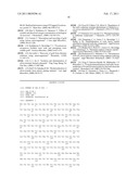 |  |
 |  |
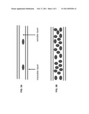 | 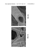 |
 | 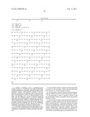 |
 |  |
 |  |
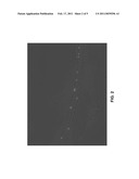 | 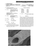 |
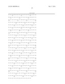 | 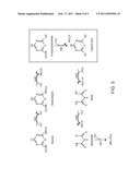 |
| New patent applications in this class: | |
| Date | Title |
|---|---|
| 2019-05-16 | Non-invasive method for assessing the presence and severity of esophageal varices |
| 2019-05-16 | Method for evaluating protrusion-forming ability of cell spheroids |
| 2019-05-16 | Product demonstration device |
| 2019-05-16 | In vitro model for blood-brain barrier and method for producing in vitro model for blood-brain barrier |
| 2019-05-16 | Microbeads for cell culture and method of monitoring cell culture using the same |
| New patent applications from these inventors: | |
| Date | Title |
|---|---|
| 2020-03-19 | Methods of attaching a molecule-of-interest to a microtube |
| 2020-03-19 | Method of attaching a cell-of-interest to a microtube |
| Top Inventors for class "Chemistry: molecular biology and microbiology" | |
| Rank | Inventor's name |
|---|---|
| 1 | Marshall Medoff |
| 2 | Anthony P. Burgard |
| 3 | Mark J. Burk |
| 4 | Robin E. Osterhout |
| 5 | Rangarajan Sampath |