Patent application title: Method and apparatus for well casing shoe seal
Inventors:
Thomas A. La Rovere (Santa Ynez, CA, US)
Dan Morrison (Katy, TX, US)
IPC8 Class: AE21B3313FI
USPC Class:
166277
Class name: Wells processes repairing object in well
Publication date: 2011-02-17
Patent application number: 20110036570
Inventors list |
Agents list |
Assignees list |
List by place |
Classification tree browser |
Top 100 Inventors |
Top 100 Agents |
Top 100 Assignees |
Usenet FAQ Index |
Documents |
Other FAQs |
Patent application title: Method and apparatus for well casing shoe seal
Inventors:
Dan Morrison
Thomas A. La Rovere
Agents:
Thomas A. La Rovere
Assignees:
Origin: SANTA YNEZ, CA US
IPC8 Class: AE21B3313FI
USPC Class:
Publication date: 02/17/2011
Patent application number: 20110036570
Abstract:
A method and apparatus is disclosed to seal and prevent fluidic
communication in the annulus between a cemented and drilled through
casing float shoe and a well-bore formation. The present invention
provides a component that installs as a coupling unit between a well
casing shoe track and a float shoe which integrates a fusible metal
alloy. After the well casing is cemented into the well-bore according to
conventional procedures, the metal alloy may be melted using a downhole
heating device deployed within the casing to a location adjacent to the
alloy, thereby causing the alloy to flow, infill, plug and seal any
incompetent cracks or micro-annulus conditions within and about the cured
cement and well-bore formation.Claims:
1. A method to plug and seal leaking channels occurring in cured well
casing cement within the annulus between the wellbore and casing in
proximity to a float shoe due to hydrostatic pressure, the method
comprising the process steps including:a) Installation of a seal coupling
component between a first casing section shoe track and a float shoe;b)
Heating of a zone in proximity about said seal coupling including said
cement infilling the well-bore and an extent of well-bore formation
wherein a fusible alloy material provided about said seal coupling is
caused to melt;c) Progression of molten alloy material through porous
channels within said cement and well-bore formations wherein materials
surrounding porous channels are heated to a temperature at or above the
melting temperature of said alloy material; andd) Re-solidification of
said alloy material to thereby plug and seal leakage channels.
2. The method of claim 1, wherein said metal is a fusible alloy comprising Bismuth, Lead or other compositions suitable for controllable melting by selective heating and re-solidification.
3. The method of claim 1, whereby said coupling component is attached to and between a first section of well casing shoe track and a float shoe.
4. The method of claim 1, wherein said coupling component includes an amount of said fusible alloy precast circumferentially on the outward surface.
5. The method of claim 1, whereby said coupling component incorporates guide rings to protect said precast alloy from scraping against the well casing bore during deployment.
6. The method of claim 1, whereby the heat for melting of said fusible alloy is provided by an electric resistance type heater or inductance type heater.
7. The method of claim 1, whereby the heat for melting said fusible alloy is provided by an exothermal-chemical reaction within said seal coupling component.
8. The method of claim 1, whereby said alloy may be subsequently re-melted.
9. A seal coupling apparatus attached to and between a conventional shoe track and a float shoe, wherein said apparatus includes the following components:a) A threaded coupling at the top end for attachment to the bottom of said shoe track;b) A threaded coupling at the bottom end for attachment to a conventional float shoe;c) A center tubular section about which an amount of fusible alloy is provided to be melted;d) Guide rings located above and below said alloy to prevent scraping said alloy material against the well-bore formation during installation
10. The apparatus of claim 8 wherein said guide rings incorporate slot features to facilitate the flow of molten alloy into micro-annulus channels.
11. The apparatus of claim 8 wherein said alloy material is cast about said center tubular section.
12. The apparatus of claim 8 wherein said alloy material cast into tubular shape and assembled as a component about said center tubular section.
13. An apparatus to be attached to the bottom section of a well casing, wherein said apparatus includes the following components:a) A coupling at the top end for attachment to said well casing,b) A tubular section to serve as a shoe track,c) A section of fusible alloy provided about the circumference of a tubular section to serve as a shoe seal component,d) A float shoe component made part of or coupled to the bottom of the shoe seal component.
14. A method to plug and seal leaking channels occurring in cured well casing annulus cement in proximity to a seal coupling due to hydrostatic pressure, the method comprising the process steps including:e) Installation of one or more seal coupling components between a first and a second casing section;f) Heating of a zone in proximity about said seal coupling including said cement infilling the well-bore and an extent of well-bore formation wherein a fusible alloy material provided about said seal coupling is caused to melt;g) Progression of molten alloy material through porous channels within said cement and well-bore formations wherein materials surrounding porous channels are heated to a temperature at or above the melting temperature of said alloy material; andh) Re-solidification of said alloy material to thereby plug and seal leakage channels.
Description:
[0001]This application claims priority of Provisional Application No. U.S.
61/274,187 filed on Aug. 14, 2009 by Thomas A. La Rovere and Dan
Morrison, inventors.
CROSS-REFERENCE TO RELATED APPLICATIONS
[0002]Provisional application filed Aug. 14, 2009; Method and Apparatus for Well Casing. Shoe Seal: La Rovere, Thomas A. and Morrison, Dan.
REFERENCE CITED
[0003]U.S. Pat. No. 7,152;657 B2 Dec. 26, 2006 Bosma et al
BACKGROUND--FIELD OF INVENTION
[0004]This invention relates to equipment and methods of use for sealing and preventing leaks through channels occurring through cement that typically occur between a casing float shoe and well-bore formation to achieve a satisfactory shoe pressure test to thereby ensure zonal isolation integrity. Satisfactory pressure testing is required to allow the well to be subsequently drilled deeper.
[0005]Typically, when constructing an oil or gas well, it is necessary to cement casing within the well-bore across reservoir zones to prevent cross flow and to enable increased mud weight in order to drill into subsurface intervals that have greater bottom hole reservoir pressures than what was drilled in the prior cased section of the well. In conventional practice, after a casing is cemented in place, the float shoe is drilled through and a pressurization test is then performed to verify that the zones above the shoe are isolated.
[0006]A common and expensive problem for the industry is failure of the pressurization test that indicates the existence of fluidic communication channels through the cement around the float shoe to intervals further up hole behind the cemented casing. In such a case, it is necessary to re-squeeze the shoe with additional cement, thus requiring additional cure time followed by drilling out the cement in the float shoe and performing the pressurization test. This process is repeated as required until a satisfactory pressurization test is achieved.
SUMMARY
[0007]In accordance with the present invention is a method and apparatus to provide convenient, low cost, time and labor saving means to remediate zonal isolation pressurization integrity test failures performed during and part of well construction. Utilizing a fusible material such as lead or bismuth alloy, a "shoe seal" coupling component is incorporated with a conventional "float shoe". The fusible material may be subsequently melted by means of a downhole heater deployed to a position within the shoe seal for beneficially sealing leaks within the annulus between the casing and well-bore.
OBJECTS AND ADVANTAGES
[0008]Accordingly to the present invention, several objects and advantages include: [0009]a) A low cost shoe seal component is conveniently attached using conventional methods between the typical shoe track and float shoe. [0010]b) The installed shoe seal component is passive and provides an optional remediation process in the event of pressurization test failure. [0011]c) The remediation process to melt and resolidify the fusible alloy is much quicker and less expensive than the conventional methods that require additional repeated cement squeeze, curing times and redrilling operations. [0012]d) Multiple shoe seal components can be installed in multiple locations to provide extended additional isolation zones. [0013]e) Melting of the shoe seal fusible alloy may be accomplished by electric resistance, induction or thermo chemical reaction heaters.
BACKGROUND--DESCRIPTION OF PRIOR ART
[0014]U.S. Pat. No. 7,152,657 B2 Dec. 26, 2006 Bosma et al proclaims a method for in-situ casting in a well of a metal which expands upon solidification for the purpose to seal the cavities within well tubulars, the annuli between co-axial well tubulars, or the annulus between a well casing and the formation, or any small gap or orifice within the well or surrounding formation such as threads, leaks, pore openings, gravel packs, fractures or perforations. However, the patent does not anticipate a specific use of a fusible metal to be integrated as a permanent precast component of a well casing or associated component, nor does it disclose any method, apparatus, design or claims to this effect
BRIEF DESCRIPTION OF THE DRAWINGS
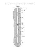
[0015]FIG. 1 is a sectional view of a typical well utilizing a conventional cement procedure with top and bottom plugs installed and cement pushed into the shoe track, the float shoe and within the well-bore annulus.
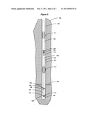
[0016]FIG. 2 is a sectional view of a typical well as in FIG. 1 with the apparatus of the present invention installed utilizing a conventional cement procedure after the wiper plugs and float shoe is drilled out with leakage paths with micro annulus leakage paths and/or channels within the well-bore cement with communication to a low pressure thief zone.
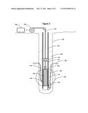
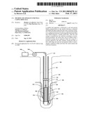
[0017]FIG. 3 is a sectional view of a typical embodiment of the present invention installed in a well after the casing has been drilled out. An electric heater deployed by means of a wireline is shown connected to topside power supply equipment and is positioned adjacent to the shoe seal coupling component. Fusible alloy is shown circumscribing the shoe seal coupling component surrounded by well annulus cement. A heated zone is indicated surrounding the apparatus where molten alloy may migrate in order to plug and seal leakage channels within the annulus cement and surrounding proximate formation.
REFERENCE NUMERALS IN DRAWINGS
[0018]100 Earth formation
[0019]101 Well-bore
[0020]102 Formation thief zone
[0021]110 Casing
[0022]111 Centralizer
[0023]112 Float collar
[0024]113 Shoe track
[0025]114 Float shoe
[0026]115 Second (top) wiper plug
[0027]116 First (bottom) wiper plug
[0028]120 Cement in shoe track
[0029]121 Cement in well-bore annulus
[0030]122 Contaminated cement
[0031]123 Leaking channel
[0032]124 Sealed channel
[0033]125 Heated zone
[0034]130 Shoe seal coupler
[0035]131 Fusible alloy
[0036]132 Shoe seal coupler male thread
[0037]133 Shoe seal coupler female thread
[0038]134 Shoe seal coupler guard ring
[0039]140 Heater
[0040]141 Downhole power cable (wireline)
[0041]142 Topside power supply equipment
[0042]143 Wireline spool
Method of Operation--Preferred Embodiment
[0043]FIG. 1 is a diagram of a conventional well casing installation. After drilling a wellbore 101 into a formation 100, casing 110 is run-in attached to which are the following components: a float collar 112; a shoe track 113 approximately forty to eighty feet long; a float shoe 114; and centralizers 111. Once said casing is positioned in the wellbore, a first wiper plug 116 is pushed down the casing to clear drill mud from the casing bore; said mud flowing through the float collar 112, the shoe track 113, the float shoe 114 and into the annulus between said casing and wellbore. Cement 121 is then pushed downward by means of a second wiper plug 115 in the same manner through said casing; said cement flowing into and infilling the shoe track and the annulus between said casing and wellbore.
[0044]FIG. 2 is the same as FIG. 1 with the addition of the apparatus of the present invention shown installed between said shoe track 113 and said float shoe 114. The apparatus consists of a shoe seal coupler 130 made from a tubular rigid body section from a material as like well casing, circumscribed by a volume of fusible alloy 131. The top end of the shoe seal coupler provides an industry standard female thread (box end) 133 for engagement with a standard casing thread while the bottom end provides an industry standard male thread 132 for engagement with a standard float shoe 114. Chamfered guard rings 134 are provided at each end of said shoe seal coupler to protect said alloy 131 from scraping against the well-bore 101 during deployment. Additionally, slot features can be provided in said guard rings to facilitate the flow of molten alloy alongside the shoe seal coupler section into micro annulus channels.
[0045]Referring to FIGS. 1 and 2, after said cement is squeezed through the casing infilling said shoe track 120 and wellbore annulus 121 to thereby displace the residual drill mud, it is allowed to cure over a period of time as required; typically twelve to twenty-four hours. After said cement is cured, a drilling operation is performed through the wiper plugs 115 and 116, through the float collar 112, through the cement within the shoe track 120, through the float shoe 114 and into the cement below. Typically, the residual cement within said float shoe and extending into the bottom of the well-bore is contaminated somewhat by drill mud as indicated by 122.
[0046]Upon completion of the drilling procedure, a pressurization test is performed by applying hydrostatic pressure within the well casing 110. Any drop in pressure indicates fluidic communication between the inside of the casing 110 and the formation 100 due to incompetent cement within the well-bore annulus 121. Common failures are due to small separation gaps or channels between the cement and casing surface conventionally known as a micro-annulus condition, or by channels 123 due to contaminated cement 122 extending into low pressure formation "thief zones" 102.
[0047]It is the object of the present invention to replace the costly conventional remediation processes in the event of a pressurization (shoe test) failure, that is: 1) the injection of additional cement (cement squeeze of float shoe); 2) allowance of time for curing of said injected cement (set time of approximately twelve to twenty-four hours); and 3) drilling out of said injected cement. In practice, this expensive remediation procedure may need to be repeated in attempt to achieve a satisfactory pressure test.
[0048]FIG. 3 is a diagram of the present invention installed in a well casing after said drilling procedure. It depicts a much simpler, more economical and faster remediation process by means of melting preinstalled alloy 131 incorporated as part of a shoe seal coupler 130 by application of a downhole deployed heat source 140. The source of heat may be provided as convenient by any of the following means including: a) a wireline deployed electric heater; b) an exothermic chemical reaction; c) a mechanical friction device driven by a typical drilling mud motor; or d) by an electric heater driven by a downhole electric mud motor electric generator. Typically, the temperature to melt a common bismuth tin fusible eutectic alloy is 138 dg C.
[0049]As alloy 131 melts, it flows by gravity into any exposed open leaking channels 123 within the heated well-bore zone 125 above the melting point temperature of said alloy thereby sealing said leaking channel as in 124. Molten alloy may also flow through said leaking channels that route to a low pressure formation thief zone 102. Additionally, molten alloy may also beneficially flow within the heated zone 125 into unconsolidated or porous formation material and the typically contaminated cement 122 near and at the bottom of the well-bore thereby improving structural composition of the material matrix. Once cooled below the melting temperature, the alloy re-solidifies forming an impervious high pressure rated seal. The process to remelt the alloy may be subsequently repeated as deemed beneficial.
Additional and Alternative Embodiments
[0050]A further embodiment of the apparatus incorporates the associated components of the shoe seal coupler 130, the alloy 131 and float shoe 114 as a single integrated unit in order to facilitate manufacturing, handling and installation.
[0051]A further embodiment of the apparatus includes a precast tubular shaped alloy material component to be assembled about the shoe seal coupler 130.
[0052]A further embodiment of the apparatus includes the casting of alloy material 131 directly to and about the shoe seal coupler 130.
[0053]A further embodiment of the invention utilizes one or more of said seal coupler 130 with alloy 131 as a coupling device between casing sections to provide a means to plug and seal annulus cement leakage channels.
[0054]A further embodiment of the invention utilizes a plurality of said seal couplers connected in series to provide a means to plug and seal annulus cement leakage channels.
[0055]While various embodiments of the present invention have been described above, it should be understood that they have been presented by way of example only, and not of limitation. Likewise, the various diagram s may depict and example configuration for the invention, which is done to aid in understanding features and functionality that can be included in the invention. The invention is not restricted to the illustrated example configurations, but can be implemented using a variety of alternative configurations. Additionally, although the invention is described in terms of various exemplary embodiments and implementations, it should be understood that the various features and functionality described in one or more of the individual embodiments are not limited in their applicability to the particular embodiment with which they are described, but instead can be applied, alone or in some combination, to one or more of the other embodiments of the invention, whether or not such embodiments are described and whether or not such features are presented as being part of a described embodiment.
[0056]Thus the breadth and scope for the present invention should not be limited by any of the above-described embodiments.
[0057]Terms and phrases used in this document, and variations thereof, unless otherwise expressly stated, should be construed as open ended as opposed to limiting. As examples of the foregoing: the term "including" should be read as to mean "including without limitation" or the like; the term "example" is used to provide exemplary instances of the item in discussion, not an exhaustive or limiting list thereof; and the adjectives such as "conventional", "traditional", "normal", "standard", "known" and terms of similar meaning, should not be construed as limiting the item described to a given time period or to an item available as of a given time, but instead should be read to encompass conventional, traditional, normal or standard technologies that may be available or known now or at any time in the future. Likewise, a group of items linked with the conjunction "and", should not be read as requiring that each and every one of those items be present in the grouping, but rather should be read as "and/or" unless expressly stated otherwise. Furthermore, although items, elements or components of the invention may be described or claimed in the singular, the plural is contemplated to be within the scope thereof unless limitation to the singular is explicitly stated. The presence of broadening words and phrases such as "one or more", "at least", "but not limited to" or other like phrases in some instances shall not be read to mean that the narrower case is intended or required in instances where such broadening phrases may be absent.
User Contributions:
comments("1"); ?> comment_form("1"); ?>Inventors list |
Agents list |
Assignees list |
List by place |
Classification tree browser |
Top 100 Inventors |
Top 100 Agents |
Top 100 Assignees |
Usenet FAQ Index |
Documents |
Other FAQs |
User Contributions:
Comment about this patent or add new information about this topic:
| People who visited this patent also read: | |
| Patent application number | Title |
|---|---|
| 20160073595 | SOAKER HOSE WITH SCALABLE PERMEABLE SURFACE AREA AND METHOD |
| 20160073594 | System and Method for the Comminution and Harvesting of Trees and Brush Type Vegetation |
| 20160073592 | CROP PROTECTION NETTING |
| 20160073591 | RECONFIGURABLE SOLAR ARRAY AND METHOD OF MANAGING CROP YIELD USING THE SAME |
| 20160073590 | CONTAINER WITH TEAR-AWAYS |
Images included with this patent application:
 |  |
 |  |
| Similar patent applications: | |
| Date | Title |
|---|---|
| 2010-07-15 | Well tools incorporating valves operable by low electrical power input |
| 2009-03-05 | Well remediation using downhole slurry |
| 2009-12-17 | Method and apparatus for a monodiameter wellbore, monodiameter casing, monobore, and/or monowell |
| 2011-03-10 | Well repair using swellable material in a remedial matrix |
| 2011-10-06 | Well assembly with recesses facilitating branch wellbore creation |
| New patent applications in this class: | |
| Date | Title |
|---|---|
| 2017-08-17 | Methods and appartus for use in oil and gas well completion |
| 2016-04-21 | Member for hydrocarbon resource collection downhole tool |
| 2015-10-29 | Sealing device and method for sealing fractures or leaks in wall or formation surrounding tube-shaped channel |
| 2014-11-06 | Vortex plunger arrangement |
| 2014-10-30 | Compositions and methods for well completions |
| New patent applications from these inventors: | |
| Date | Title |
|---|---|
| 2010-08-12 | Method and apparatus for multi-zone stimulation |
| Top Inventors for class "Wells" | |
| Rank | Inventor's name |
|---|---|
| 1 | Michael L. Fripp |
| 2 | Jean Marc Lopez |
| 3 | Michael H. Johnson |
| 4 | Jørgen Hallundbaek |
| 5 | Dennis P. Nguyen |