Patent application title: Sample Cup Container
Inventors:
Donato Pompa (Port St. Lucie, FL, US)
IPC8 Class: AB65D2500FI
USPC Class:
220600
Class name: Receptacles end wall structure
Publication date: 2011-02-03
Patent application number: 20110024434
Inventors list |
Agents list |
Assignees list |
List by place |
Classification tree browser |
Top 100 Inventors |
Top 100 Agents |
Top 100 Assignees |
Usenet FAQ Index |
Documents |
Other FAQs |
Patent application title: Sample Cup Container
Inventors:
Donato Pompa
Agents:
The Intellect Law Group
Assignees:
Origin: PALM CITY, FL US
IPC8 Class: AB65D2500FI
USPC Class:
Publication date: 02/03/2011
Patent application number: 20110024434
Abstract:
A novel shipping and inspection container for multiple XRF sample cups.Claims:
1. A sample cup container comprising four sides and a bottom; wherein the
bottom contains a circular cutout situated so as to correspond with the
placement of a sample cup when said cup is placed within the container.
2. The sample cup container of claim 1 further comprising a first flap situated along the top edge of a container first side; said flap extending over the container open top.
3. The sample cup container of claim 1 further comprising a first flap situated along the top edge of a container first side; said flap extending over the container open top and a second flap situated along the top edge of a container second side; said second side parallel to said first side and said second flap extending over the container open top.
4. The sample cup container of claim 2 wherein said first flap, when extended over the container open top, completely covers said container open top.
5. The sample cup container of claim 1 further comprising a removable film placed upon the bottom outer surface of the container.
Description:
FIELD OF THE INVENTION
[0001]This invention relates to the design and construction of a novel shipping and inspection container for multiple XRF sample cups.
BACKGROUND OF THE INVENTION
[0002]The present invention describes a shipping and inspection container for XRF sample cups specially designed with pre-installed film at their bottom surface. The sample cups are packed within the rectangular shaped container, which includes display cutouts along its bottom for inspection of the liquid samples contained within the sample cups. The container includes upwardly projecting tabs located on opposite sides, facilitating stacking of the container/cup combinations for shipping and for aiding in handling of the containers. The containers are intended to be used in combination with specially designed sample cups including caps with prominent stems for aiding in removal of each individual sample cup from the container for testing.
[0003]Spectroscopic analysis (XRF Spectroscopy) utilizes sample cups to contain liquid or gas samples for inspection. Sample cups generally have a thin transparent film bottom and may include a top end formed integral with the cup body known as a single ended design. Alternatively, the sample cup may include a second thin film or be capped at the top end, known as a double open end design. Prior art sample cups are generally delivered to the analyst in parts comprised of a side wall member and complementary secondary member, which members are assembled in combination with a separate thin film component to construct a single sample cup. The sample cup, with its liquid or gas sample contained therein, is then manually transported to an XRF machine and placed in a holder, thin film bottom down, for analysis. Most often, multiple sample cups, each containing a single sample, are intended to be tested contemporaneously, as part of a study. While multiple sample cups may be transported via tray or other implement to the analysis site, such a method is not optimal as the tray may contaminate or damage the thin film outer surface, affecting analysis. Furthermore, such a method hinders ready visual identification of various samples by covering the thin film "window" and requiring manual handling of each sample cup to allow visual identification of the sample contained therein.
[0004]Finally, pre-assembled sample cups, including a thin film bottom, are available. While pre-assembled sample cups minimize time and effort to properly assemble a sample cup for testing, they create logistical problems for delivery and storage due to the fragile nature of the thin film component. Unlike conventional unassembled cup member components, pre-assembled cups cannot be bulk packed for shipment or storage due to the high probability of damage or contamination to the thin film surface on the sample cup bottom.
[0005]In view of the prior arts' shortcomings, it is thus desirable to create a container which facilitates contaminant-free handling of multiple sample cups at both the delivery and storage stage and during sample cup test usage.
BRIEF DESCRIPTION OF THE DRAWINGS
[0006]FIGS. 1A-1F are various views (elevations) of one embodiment of the sample cup container.
[0007]FIGS. 2A-2C are various views (elevations) of the sample cup container with 2 sample cups contained therein.
[0008]FIGS. 3A-3B are various views (elevations) of the sample cup container when fully loaded with sample cups contained therein.
DETAILED DESCRIPTION OF THE INVENTION
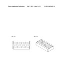
[0009]Shown in FIG. 1A is a top view of the empty sample cup container evidencing the bottom (2) containing eight circular cutouts (4) and a first flap (6) and second flap (8).
[0010]FIG. 1B is another view of the empty sample container better illustrating the four sides (1) and bottom (2), the bottom containing circular cutouts (4), and a first flap (6) and a second flap (8).
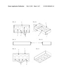
[0011]FIGS. 1C and 1D are side view elevations each showing a side (1) of the container.
[0012]FIG. 1E is a bottom view of the container illustrating the bottom (2) with circular cutouts (4) and indicating the first flap (6) and second flap (8), each partially observable through the cutouts.
[0013]FIG. 1F is an alternate bottom view of the empty sample container better illustrating the sides of the container and bottom, the bottom containing the circular cutouts.
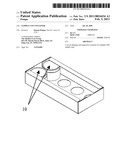
[0014]FIGS. 2A-2C are various views (elevations) of the sample cup container as shown in FIGS. 1A-1F but with 2 sample cups (10) contained therein. The thin film window on the bottom of the sample cups is observable through the circular cutouts on the bottom of the sample cup container, as illustrated in FIG. 2C, facilitating identification and contaminant-free handling of multiple sample cups.
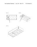
[0015]FIGS. 3A-3B are various views (elevations) of the sample cup container as shown in FIGS. 1A-1F but fully loaded with sample cups.
[0016]While the first flap and second flap, as illustrated, facilitate retention of the sample cups within the container, alternative embodiments may substitute a single flap or omit the flaps without digressing from the spirit of the invention.
[0017]Furthermore, the dimensions of the container and the number of circular cutouts may be altered or amended to meet industry needs or requirements without digressing from the spirit of the invention.
User Contributions:
comments("1"); ?> comment_form("1"); ?>Inventors list |
Agents list |
Assignees list |
List by place |
Classification tree browser |
Top 100 Inventors |
Top 100 Agents |
Top 100 Assignees |
Usenet FAQ Index |
Documents |
Other FAQs |
User Contributions:
Comment about this patent or add new information about this topic:
| People who visited this patent also read: | |
| Patent application number | Title |
|---|---|
| 20110029802 | INFORMATION PROCESSING SYSTEM |
| 20110029801 | Method and System for Balancing Receive-Side Supply Load |
| 20110029800 | System and Method for Pre-Detection in a Power Over Ethernet System |
| 20110029799 | Power management system and method |
| 20110029797 | MANAGING MEMORY POWER USAGE |
Images included with this patent application:
 |  |
 |  |
| Similar patent applications: | |
| Date | Title |
|---|---|
| 2012-07-26 | Stackable baking cup container |
| 2012-02-02 | Multiple compartment container |
| 2008-09-11 | Vacuum seal cover of circular container |
| 2009-04-16 | Stackable cover for container |
| 2009-08-13 | Disposable fluid container |
| New patent applications in this class: | |
| Date | Title |
|---|---|
| 2016-06-09 | Stemware with magnifying base and light source |
| 2016-05-05 | Intermediate bulk container and valve opening/closing device therefor |
| 2015-04-23 | Refill system |
| 2015-03-26 | Composite materials |
| 2014-10-09 | Adaptable bin with retractable cup holder |
| Top Inventors for class "Receptacles" | |
| Rank | Inventor's name |
|---|---|
| 1 | Daniel Lee Bizzell |
| 2 | Frank Yang |
| 3 | Terry Vovan |
| 4 | William P. Apps |
| 5 | Lowell L. Wood, Jr. |