Patent application title: COMPOSITE PLATE CABINET
Inventors:
Luhao Leng (Fujian, CN)
IPC8 Class: AA47B9620FI
USPC Class:
3122655
Class name: Supports: cabinet structure knockdown or setup type connecting panels
Publication date: 2011-01-13
Patent application number: 20110006651
Inventors list |
Agents list |
Assignees list |
List by place |
Classification tree browser |
Top 100 Inventors |
Top 100 Agents |
Top 100 Assignees |
Usenet FAQ Index |
Documents |
Other FAQs |
Patent application title: COMPOSITE PLATE CABINET
Inventors:
Luhao Leng
Agents:
RABIN & Berdo, PC
Assignees:
Origin: WASHINGTON, DC US
IPC8 Class: AA47B9620FI
USPC Class:
Publication date: 01/13/2011
Patent application number: 20110006651
Abstract:
A composite plate cabinet includes plurality of supporting plates and
plurality of inner barrier plates. Said supporting plates include some
side supporting plates and some transverse supporting plates. The
plurality of supporting plates are coupled and fixed to form a framework.
The inner barrier plates are coupled between the supporting plates, in
this way plurality of putting spaces are formed by the combination
between the inner barrier plates and the supporting plates. The
supporting plates and the inner barrier plates are totally or partially
composite plates. The composite plate includes a faceplate, a base plate,
a cellular inner core and inner liner elements. The cellular inner core
is filled between the faceplate and the base plate. The inner liner
elements are located between the faceplate and the base plate for
connecting the composite plates and enhancing the structure.Claims:
1. a composite plate cabinet includes some supporting plates and some
inner barrier plates; the supporting plates includes some side supporting
plates and some transverse supporting plates; some supporting plates are
coupled and fixed to form a framework; the inner barrier plates are
coupled between the supporting plates; some putting spaces are formed by
the combination between the inner barrier plates and the supporting
plates; has characters as follows: said supporting plates and said inner
barrier plates are totally or partially composite plates; the composite
plate includes a faceplate, a soleplate, a honeycomb inner core and inner
liner pieces; the honeycomb inner core is filled between the faceplate
and the soleplate; the inner liner pieces are sandwiched between the
faceplate and the soleplate for connecting the composite plates and
enhancing the structure.
2. the composite plate cabinet according to claim 1, has characters as follows: the inner liner pieces entirely or partially wrap the honeycomb inner core along the circumference of the honeycomb inner core and are disposed at the joints of the supporting plates or the joints of the supporting plates and the inner barrier plates.
3. the composite plate cabinet according to claim 1, has characters as follows: said inner barrier plates are composite plates having the same structure with above supporting plates, or composite plates without inner liner pieces.
4. the composite plate cabinet according to claim 1, has characters as follows: said composite plates have inner liner pieces locally; the inner liner pieces are directly laminated on or below the honeycomb inner core.
5. the composite plate cabinet according to claim 1, has characters as follows: said inner liner pieces of the composite plate are framework; circumference of underside of the framework are welded with corners made by outspread sheets and lay aboard one side of the soleplate or the faceplate.
6. the composite plate cabinet according to claim 1, has characters as follows: the honeycomb inner core of the composite plate can be integrative and is set in the center of the inner liner pieces, or has some pieces being in or out of the inner liner pieces.
7. the composite plate cabinet according to claim 1, has characters as follows: the fixed connection mode is hanging-connection between the supporting plates, or between the inner barrier plates, or between the supporting plate and the inner barrier plate.
8. the composite plate cabinet according to claim 7, has characters as follows: said inner barrier plate is composite plate having the same structure with the supporting plate; the some supporting plates are all composite plates; each two composite plates of hanging connection: a first plastic composite board with inner liner pieces embedded in it, the inner liner pieces have buckling groove exposed to a second plastic composite plate; the second plastic composite plate with a reinforcement piece or inner liner pieces embedded in it; the reinforcement piece or the inner liner pieces fixedly have fastener protruding outside of the second plastic composite plate; the first plastic composite plate is fixedly connected to the second plastic composite board by the fastener buckling into the buckling groove.
9. the composite plate cabinet according to claim 1, has characters as follows: the faceplate and the soleplate of said plastic composite plate are combined plates of plastic plates formed by vacuum forming; superposition sides of the faceplate and the soleplate locates at side face or underside of the plastic composite plate; superposition sides of the faceplate and the soleplate connect with each other by welding or glue.
10. the composite plate cabinet according to claim 1, has characters as follows: both faceplate and soleplate of said plastic composite plate are plastic sheet materials; periphery of the faceplate and the soleplate are wrapped by side enveloped pieces.
11. the composite plate cabinet according to claim 9, has characters as follows: margins of faceplate and soleplate of the plastic composite plate are of superposition and connect with each other; circumference of the soleplate protrudes entad to form a sidestep; height of the sidestep is equal to the thickness of the faceplate; the margin of the faceplate cooperates with the sidestep.
12. the composite plate cabinet according to claim 8, has characters as follows: circumference of the soleplate bends upwards and partly wraps the side of the inner liner piece; circumference of the faceplate bends downwards and wraps the side of the inner liner piece and the circumference of the soleplate; the side of the faceplate connects with the soleplate at the side of the inner liner piece.
13. the composite plate cabinet according to claim 8, has characters as follows: circumference of the soleplate keeps close to the bottom side of the inner liner piece; circumference of the soleplate fixedly connects the middle of the bottom side of the inner liner piece; the circumference of the faceplate bends downwards and wraps the side of the inner liner; the side of the faceplate fixedly connects the side of the soleplate at the bottom side of the inner liner piece.
14. the composite plate cabinet according to claim 1, has characters as follows: said honeycomb paper core is constituted by single-layer honeycomb paper cores.
15. the composite plate cabinet according to claim 14, has characters as follows: said honeycomb paper core is constituted by single-layer honeycomb paper plates; the honeycomb paper plate is constituted by honeycomb paper core, face paper, bottom paper; the honeycomb paper core is sandwiched between the face paper and the bottom paper and fixedly glues the face paper and the bottom paper.
16. the composite plate cabinet according to claim 8, has characters as follows: said fastener is plastic hook, L-shaped metal piece, L-shaped sheet piece or sidestep pin; said buckling groove is rectangular, elliptical or sidestep-shaped; the buckling groove cooperates with the fastener.
17. the composite plate cabinet according to claim 8, has characters as follows: the first plastic composite plate fixedly connects with the second plastic composite plate by L-shaped, T-shaped or -- shaped.
18. A composite plate cabinet, comprising some supporting plates and some inner barrier plates; the inner barrier plates fixedly connect with the supporting plates; the supporting plates connect with each other to form cabinet framework; some putting spaces are formed by the combination between the inner barrier plates and the supporting plates; has characters as follows: said supporting plates and inner barrier plates are all or partly composite plates; the composite plate comprises faceplate, soleplate, inner liner piece and honeycomb inner core; the inner liner piece bassets outside partly and partly wraps the honeycomb inner core, the faceplate and the soleplate.
19. a composite plate cabinet, comprising a framework and some inner barrier plates; the inner barrier plate fixedly connects outer framework; some putting spaces are formed by the combination between the inner barrier plates and outer framework; the outer framework is made by metal pipe pieces; has characters as follows: the inner barrier plates are all or partly composite plates; the composite plates comprise faceplate, soleplate, honeycomb inner core; the honeycomb inner core is filled between the faceplate and the soleplate.
20. the composite plate cabinet according to claim 19, has characters as follows: said composite plate also comprises inner liner piece; the inner liner piece entirely or partially wrap the honeycomb inner core along the circumference of the honeycomb inner core and are disposed at the joints of the supporting plates or the joints of the supporting plates and the inner barrier plates.
21. a composite plate cabinet, comprising some supporting plates and some inner barrier plates; the supporting plates includes some side supporting plates and some transverse supporting plates; some supporting plates are coupled and fixed to form a framework; the inner barrier plates are coupled between the supporting plates; some putting spaces are formed by the combination between the inner barrier plates and the supporting plates; has characters as follows: said supporting plates and inner barrier plates are all or partly composite plates; the composite plate comprises faceplate, soleplate, plastic epispastic inner core and inner liner piece; the plastic epispastic inner core is filled between the faceplate and the soleplate; the inner liner piece is sandwiched between the faceplate and the soleplate for connecting the composite plates and enhancing the structure.
22. the composite plate cabinet according to claim 10, has characters as follows: margins of faceplate and soleplate of the plastic composite plate are of superposition and connect with each other; circumference of the soleplate protrudes entad to form a sidestep; height of the sidestep is equal to the thickness of the faceplate; the margin of the faceplate cooperates with the sidestep.
Description:
TECHNICAL FIELD
[0001]The present invention relates to a cabinet, particularly to a composite plate cabinet constituted by plastic composite plates.
BACKGROUND ART
[0002]In modern furniture, cabinet is widely used in office and bedroom because of its practicability. But known cabinet is mostly made by wood. Accompanying recognition of entironment protection of people, the cabinet made by wood is gradually replaced by the cabinet made by plastic. Known cabinet made by plastic plate has disadvantages as follows: firstly, plastic plates of the cabinet can't support bigger weight; secondly, plastic plates of cabinet have a low connection intensity with each other; thirdly, connection of plastic plates of cabinet is not knock-down, which will occupying big room in storage or portage; fourthly, it adopts solid plastic plate to boost the intensity of plastic plates of cabinet, which has a great weight and wastes materials.
SUMMARY OF THE PRESENT INVENTION
[0003]One purpose of the present invention is to provide a new composite plate for cabinet.
[0004]Another purpose of the present invention is to provide a composite cabinet, which has high connection intensity, is knock-down, is connected easily.
[0005]The present invention adopts technical schemes as follows: A composite plate cabinet includes some supporting plates and some inner barrier plates; the supporting plates includes side supporting plates and transverse supporting plates; some supporting plates are coupled and fixed to form a framework; the inner barrier plates are coupled between the supporting plates; some putting spaces are formed by the combination between the inner barrier plates and the supporting plates; said supporting plates and said inner barrier plates are totally or partially composite plates; the composite plate includes a faceplate, a soleplate, a honeycomb inner core and inner liner pieces; the honeycomb inner core is filled between the faceplate and the soleplate; the inner liner pieces are sandwiched between the faceplate and the soleplate for connecting the composite plates and enhancing the structure.
[0006]Said inner liner pieces entirely or partially wrap the honeycomb inner core along the circumference of the honeycomb inner core and are disposed at the joints of the supporting plates or the joints of the supporting plates and the inner barrier plates. Said inner barrier plates are composite plates having the same structure with above supporting plates, or composite plates without inner liner pieces.
[0007]Said composite plate has inner liner pieces locally; the inner liner pieces are directly laminated on or below the honeycomb inner core. In this structure, there is no containing space for the inner liner piece in the honeycomb inner core; the inner liner piece can connect with other parts by usual connecting mode, such as bolts.
[0008]Said inner liner pieces of the composite plate are frameworks; circumference of underside of the framework are welded with corners made by outspread sheets and lay aboard one side of the soleplate or the faceplate.
[0009]The honeycomb inner core of the composite plate can be integrative and is set in the center of the inner liner piece, or has some pieces being in or out of the inner liner piece.
[0010]The fixed connection mode is hanging-connection between the supporting plates, or between the inner barrier plates, or between the supporting plate and the inner barrier plate.
[0011]Said inner barrier plate is composite plate having the same structure with the supporting plate; the some supporting plates are all plastic composite plates; each two composite plates of hanging connection: a first plastic composite board with an inner liner piece being embedded in it, the inner liner piece has buckling groove exposed to a second plastic composite plate; the second plastic composite plate with a reinforcement piece or an inner liner piece in it, the reinforcement piece of the inner liner piece fixedly having fastener protruding outside of the second plastic composite plate; the first plastic composite plate is fixedly connected to the second plastic composite board by the fastener buckling into the buckling groove.
[0012]The faceplate and the soleplate of said plastic composite plate are combined plates of plastic plates formed by vacuum forming; superposition sides of the faceplate and the soleplate locates at side face or underside of the plastic composite plate; superposition sides of the faceplate and the soleplate connect with each other by welding or glue.
[0013]Both faceplate and soleplate of said plastic composite plate are plastic sheet materials; periphery of the faceplate and the soleplate are wrapped by side enveloped piece.
[0014]Margins of faceplate and soleplate of the plastic composite plate are of superposition and connect with each other; circumference of the soleplate protrudes entad to form a sidestep; height of the sidestep is equal to the thickness of the faceplate; the margin of the faceplate cooperates with the sidestep.
[0015]Circumference of the soleplate bends upwards and partly wraps the side of the inner liner piece; circumference of the faceplate bends downwards and wraps the side of the inner liner piece and the circumference of the soleplate; the side of the faceplate connects with the soleplate at the side of the inner liner piece.
[0016]Circumference of the soleplate keeps close to the bottom side of the inner liner piece; circumference of the soleplate fixedly connects the middle of the bottom side of the inner liner piece; the circumference of the faceplate bends downwards and wraps the side of the inner liner; the side of the faceplate fixedly connects the side of the soleplate at the bottom side of the inner liner piece.
[0017]Said honeycomb is honeycomb paper core, the honeycomb paper core can be integrative and is set in the center of the inner liner piece, or has some pieces being in or out of the inner liner piece.
[0018]Said honeycomb paper core is constituted by single-layer honeycomb paper core.
[0019]Said honeycomb paper core is constituted by single-layer honeycomb paper plate; the honeycomb paper plate is constituted by honeycomb paper core, face paper, bottom paper; the honeycomb paper core is sandwiched between the face paper and the bottom paper and fixedly glues the face paper and the bottom paper.
[0020]Said fastener is plastic hook, L-shaped metal piece, L-shaped sheet piece or sidestep pin; said buckling groove is rectangular, elliptical or sidestep-shaped; the buckling groove cooperates with the fastener.
[0021]The first plastic composite plate fixedly connects with the second plastic composite plate by L-shaped, T-shaped or -- shaped.
[0022]The present invention also adopts technical schemes as follows:
[0023]A composite plate cabinet, comprising some supporting plates and some inner barrier plates; the inner barrier plates fixedly connect with the supporting plates; the supporting plates connect with each other to form cabinet framework; some putting spaces are formed by the combination between the inner barrier plates and the supporting plates; said supporting plates and inner barrier plates are all or partly composite plates; the composite plate comprises faceplate, soleplate, inner liner piece and honeycomb inner core; the inner liner piece bassets outside partly and partly wraps the honeycomb inner core, the faceplate and the soleplate. Or another scheme: a composite plate cabinet, comprising a framework and some inner barrier plates; the inner barrier plate fixedly connects outer framework; some putting spaces are formed by the combination between the inner barrier plates and outer framework; the outer framework is made by metal pipe pieces; the inner barrier plates are all or partly composite plates; the composite plates comprise faceplate, soleplate, honeycomb inner core; the honeycomb inner core is filled between the faceplate and the soleplate.
[0024]Said composite also comprises inner liner piece; the inner liner piece entirely or partially wrap the honeycomb inner core along the circumference of the honeycomb inner core and are disposed at the joints of the supporting plates or the joints of the supporting plates and the inner barrier plates.
[0025]The honeycomb inner core of the present invention can be replaced by plastic epispastic materials, especially an epispastic sheet piece.
[0026]According above description about the present invention, comparing with background art, the present invention has virtues as follows: firstly, the cabinet of the present invention has a light weight and a high intensity; secondly, connection of every plastic composite plates has a high connection intensity and is connected easily; thirdly, the plastic composite plate of the cabinet of the present invention has a high intensity; fourthly, reinforcement piece is embedded in the plastic composite plate, has a beautiful appearance, is machinged easily, is used safely (reinforcement piece will not scratch users or their clothes); fifthly, the connection of the cabinet of the present invention is disconnected, which occupies smaller room when in storage or portage; sixthly, the inner liner piece can be used as reinforcement piece directly, to make the outer framework has a beautiful appearance, at the same time the cabinet has a light weight, has a high intensity, has a high connection intensity, is connected expediently.
BRIEF DESCRIPTION OF ATTACHED DRAWINGS
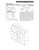
[0027]FIG. 1 is a sketch map of three-dimensional structure of the composite clothespress in embodiment 1 of the present invention.
[0028]FIG. 2 is a sketch map of section plane of plastic composite plate one in embodiment 1 of the present invention.
[0029]FIG. 2.1 is an explosive view of the composite plate one in embodiment 1 of the present invention.
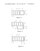
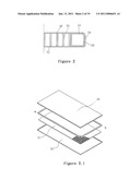
[0030]FIG. 3 is a sketch map of section plane of plastic composite plate two in embodiment 1 of the present invention.
[0031]FIG. 4 is a sketch map of section plane of plastic composite plate three in embodiment 1 of the present invention.
[0032]FIG. 5 is a sketch map of section plane of plastic composite plate four in embodiment 1 of the present invention.
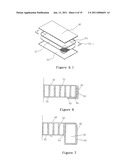
[0033]FIG. 5.1 is an explosive view of the plastic composite plate four in embodiment 1 of the present invention.
[0034]FIG. 6 is a sketch map of section plane of plastic composite plate five in embodiment 1 of the present invention.
[0035]FIG. 7 is a sketch map of section plane of plastic composite plate six in embodiment 1 of the present invention.
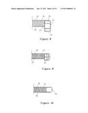
[0036]FIG. 8 is a sketch map of section plane of plastic composite plate seven in embodiment 1 of the present invention.
[0037]FIG. 9 is a sketch map of section plane of plastic composite plate eight in embodiment 1 of the present invention.
[0038]FIG. 10 is a sketch map of section plane of plastic composite plate nine in embodiment 1 of the present invention.
[0039]FIG. 11 is a sketch map of section plane of plastic composite plate ten in embodiment 1 of the present invention.
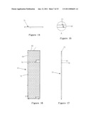
[0040]FIG. 12 is a sketch map of section plane of the plastic composite plate of left supporting plate in embodiment 1 of the present invention.
[0041]FIG. 13 is a front view of the plastic composite plate of left supporting plate in embodiment 1 of the present invention.
[0042]FIG. 14 is a planform of the plastic composite plate of left supporting plate in embodiment 1 of the present invention.
[0043]FIG. 15 is an enlarged drawing of A in the FIG. 12.
[0044]FIG. 16 is a sketch map of section plane of the plastic composite plate of right supporting plate in embodiment 1 of the present invention.
[0045]FIG. 17 is a front view of the plastic composite plate of right supporting plate in embodiment 1 of the present invention.
[0046]FIG. 18 is a planform of the plastic composite plate of right supporting plate in embodiment 1 of the present invention.
[0047]FIG. 19 is an enlarged drawing of B in the FIG. 19.
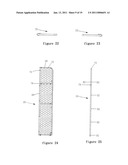
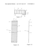
[0048]FIG. 20 is a sketch map of section plane of the plastic composite plate of left inner barrier plate in embodiment 1 of the present invention.
[0049]FIG. 21 is a front view of the plastic composite plate of left inner barrier plate in embodiment 1 of the present invention.
[0050]FIG. 22 is a planform of the plastic composite plate of left inner barrier plate in embodiment 1 of the present invention.
[0051]FIG. 23 is a planform of the plastic composite plate of right inner barrier plate in embodiment 1 of the present invention.
[0052]FIG. 24 is a sketch map of section plane of the plastic composite plate of right inner barrier plate in embodiment 1 of the present invention.
[0053]FIG. 25 is a front view of the plastic composite plate of right inner barrier plate in embodiment 1 of the present invention.
[0054]FIG. 26 is a sketch map of section plane of the plastic composite plate of left-back supporting plate in embodiment 1 of the present invention.
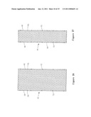
[0055]FIG. 27 is a sketch map of section plane of the plastic composite plate of middle-back supporting plate in embodiment 1 of the present invention.
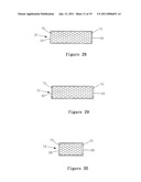
[0056]FIG. 28 is a front view of the plastic composite plate of left-upper transverse supporting plate in embodiment 1 of the present invention.
[0057]FIG. 29 is a sketch map of section plane of the plastic composite plate of right-upper transverse supporting plate in embodiment 1 of the present invention.
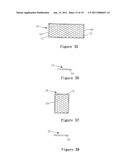
[0058]FIG. 30 is a sketch map of section plane of the plastic composite plate of middle-upper transverse supporting plate in embodiment 1 of the present invention.
[0059]FIG. 31 is a sketch map of section plane of the plastic composite plate of left-lower transverse supporting plate in embodiment 1 of the present invention.
[0060]FIG. 32 is a left elevation of the plastic composite plate of left-lower transverse supporting plate in embodiment 1 of the present invention.
[0061]FIG. 33 is a sketch map of section plane of the plastic composite plate of left-middle plate in embodiment 1 of the present invention.
[0062]FIG. 34 is a left elevation of the plastic composite plate of left-middle plate in embodiment 1 of the present invention.
[0063]FIG. 35 is a sketch map of section plane of the plastic composite plate of left transverse inner barrier plate in embodiment 1 of the present invention.
[0064]FIG. 36 is a left elevation of the plastic composite plate of left transverse inner barrier plate in embodiment 1 of the present invention.
[0065]FIG. 37 is a sketch map of section plane of the plastic composite plate of middle transverse inner barrier plate in embodiment 1 of the present invention.
[0066]FIG. 38 is a left elevation of the plastic composite plate of middle transverse inner barrier plate in embodiment 1 of the present invention.
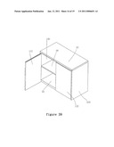
[0067]FIG. 39 is a sketch map of three-dimensional structure of unattached cabinet with door in embodiment 2 of the present invention.
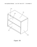
[0068]FIG. 40 is a sketch map of section plane of the plastic composite plate of top door plate in embodiment 2 of the present invention.
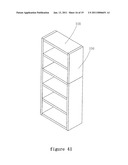
[0069]FIG. 41 is a sketch map of three-dimensional structure of unattached cabinet in embodiment 3 of the present invention.
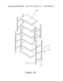
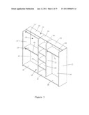
[0070]FIG. 42 is a sketch map of three-dimensional structure of composite book cabinet in embodiment 4 of the present invention.
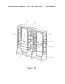
[0071]FIG. 43 is a sketch map of three-dimensional structure of composite plate cabinet in embodiment 5 of the present invention.
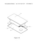
[0072]FIG. 44 is another structure explosive view of the plastic composite plate.
EMBODIMENT
[0073]We will explain the present invention referring to attached drawings. Composite plate cabinet of the present invention can be a composite clothespress, a composite unattached cabinet with door, a composite unattached cabinet, a composite book cabinet one or a composite book cabinet two.
Embodiment 1
[0074]A composite clothespress, as shown in FIG. 1, comprising a left supporting plate 10, a right supporting plate 12, upper transverse supporting plates 14, nether transverse supporting plates 16, back supporting plates 18, a left inner barrier plate 20, a right inner barrier plate 22, a left transverse inner barrier plate 24, a right transverse inner barrier plate 26 and four middle transverse inner barrier plates 28.
[0075]The left supporting plate 10, the right supporting plate 14, the upper transverse supporting plates 14 and the nether transverse supporting plates 16 connects with each other to form a rectangular outer framework.
[0076]The left inner barrier plate 20 and the right inner barrier plate 22 respectively fixedly connect to the outer framework and are parallel to the left supporting plate 10 and the right supporting plate 12.
[0077]The above upper transverse supporting plates 14 comprise a left upper transverse supporting plate 30, a middle upper transverse supporting plate 34, and a right upper transverse supporting plate 32. The left upper transverse supporting plate 30 fixedly connects to the upper head face of the left supporting plate 10 and the upper head face of the left inner barrier plate 20; the middle upper transverse supporting plate 34 fixedly connects to the upper head face of the left inner barrier plate 20 and the upper head face of the right inner barrier plate 22; the right upper transverse supporting plate 32 fixedly connects to the upper head face of the right inner barrier plate 22 and the upper head face of the right supporting plate 12.
[0078]The nether supporting plates 16 comprise a left nether transverse supporting plate 36, a middle nether transverse supporting plate 40, and a right nether transverse supporting plate 38. The left nether transverse supporting plate 36 fixedly connects to the nether head face of the left supporting plate 10 and the nether head face of the left inner barrier plate 20; the middle nether transverse supporting plate 40 fixedly connect to the nether head face of the left inner barrier plate 20 and the nether head face of the right inner barrier plate 22; the right nether transverse supporting plate 38 fixedly connects to the nether head face of the right inner barrier plate 22 and the nether head face of the right supporting plate 12.
[0079]The back supporting plates 18 comprise a left back supporting plate 42, a middle back supporting plate 46 and a right back supporting plate 44. The left back supporting plate 42 fixedly connects to the back end part of the left supporting plate 10 and the back end part of the left inner barrier 20; the middle back supporting plate 46 fixedly connects to the back end part of the left inner barrier 20 and the back end part of the right inner barrier 22; the right back supporting plate 44 fixedly connects to the back end part of the right inner barrier 22 and the back end part of the right supporting plate 12.
[0080]The left transverse inner barrier plate 24 fixedly connects to the left supporting plate 10 and the left inner barrier plate 20; the left transverse inner barrier plate 24 fixedly connects to the right inner barrier plate 22 and the right supporting plate 12; the four middle transverse inner barrier plates 28 fixedly respectively connect to the left inner barrier plate 20 and the right inner barrier plate 22 equably.
[0081]Above fixed connections all can be disconnected and are hanging connections.
[0082]The left supporting plate 10, the right supporting plate 12, the left upper transverse supporting plate 30, the middle upper transverse supporting plate 34, the right upper transverse supporting plate 32, the right nether transverse supporting plate 36, the middle nether transverse supporting plate 40, the right nether transverse supporting plate 38, the left back supporting plate 42, the middle back supporting plate 46, the right back supporting plate 44, the left inner barrier plate 20, the right inner barrier plate 22, the left transverse inner barrier plate 24, the right transverse inner barrier plate 26 and the four middle transverse inner barrier plates 28 are all plastic composite plates.
[0083]We will describe the structure of plastic composite plate firstly as follows, comprising eleven styles.
[0084]Firstly, composite plate one, as shown in FIG. 2 and FIG. 2.1, comprising a faceplate 48, a soleplate 50, a honeycomb 52 and an inner liner 54. The outer circumference of the faceplate 48 extends downwards to form a first upper margin-wrapped piece 56, or the circumference of the faceplate 48 bends downwards; the outer circumference of the soleplate 50 extends upwards to form a first nether margin-wrapped piece 58, or the circumference of the soleplate 50 bends upwards.
[0085]The cross section of the inner liner 54 likes quadrature-shaped. The honeycomb 52 is filled between the faceplate 48 and the soleplate 50; the inner liner 54 is sandwiched between the faceplate 48 and the soleplate 50; the inner liner 54 entirely covers the honeycomb along the circumference of the honeycomb. The inner side of the first nether margin-wrapped piece 58 fixedly glues the outer side of the honeycomb 52; the inner side of the first upper margin-wrapped piece 56 fixedly glues the outer side of the first nether margin-wrapped piece 58.
[0086]Secondly, composite plate two, as shown in FIG. 3, comprising a faceplate 48, a soleplate 50, a honeycomb 52 and an inner liner 54. The outer circumference of the faceplate 48 extends downwards to form a first upper margin-wrapped piece 56, the outer circumference of the soleplate 50 extends upwards to form a first nether margin-wrapped piece 58. The under part of the first nether margin-wrapped piece 58 is machininged entad to form a sidestep, whose height is about equal to the thickness of the first upper margin-wrapped 56, and the sidestep is set at the position of the nether head face of the first upper margin-wrapped piece 56.
[0087]The cross section of the inner liner 54 likes quadrature-shaped. The honeycomb 52 is filled between the faceplate 48 and the soleplate 50; the inner liner 54 is sandwiched between the faceplate 48 and the soleplate 50; the inner liner 54 entirely covers the honeycomb 52 along the circumference of the honeycomb 52. At the sidestep, the inner side of the first nether margin-wrapped piece 58 fixedly glues the outer side of the honeycomb 52; at the sidestep, the inner side of the first upper margin-wrapped piece 56 fixedly glues the outer side of the first nether margin-wrapped piece 58.
[0088]Thirdly, composite plate three, as shown in FIG. 4, comprising a faceplate 48, a soleplate 50, a honeycomb 52 and an inner liner 54. The outer circumference of the faceplate 48 extends downwards to form a first margin-wrapped piece 56; the soleplate 50 caves downwards to form a groove 60, outer supporting plate of the groove 60 forms a first nether margin-wrapped piece 58.
[0089]The under part of the first nether margin-wrapped piece 58 is machininged entad to form a sidestep, whose height is about equal to the thickness of the first upper margin-wrapped 56, and the sidestep is set at the position of the nether head face of the first upper margin-wrapped piece 56.
[0090]The cross section of the inner liner 54 likes quadrature-shaped. The depth of the groove 60 is about equal to the height of the inner liner 54. The honeycomb 52 is filled between the faceplate 48 and the soleplate 50; the inner liner 54 is sandwiched between the faceplate 48 and the soleplate 50; the inner liner 54 be fixedly glued in the groove 60. The inner side of the upside of the first upper margin-wrapped piece 56 fixedly glues the outer side of the honeycomb; at the sidestep, the inner side of the under part of the first upper margin-wrapped piece 56 fixedly glues the outer side of the first nether margin-wrapped piece 58.
[0091]Fourthly, composite plate four, as shown in FIG. 5, comprising a faceplate 48, a soleplate 50, a honeycomb 82 and an inner liner 54. Circumference of the faceplate 48 extends downwards to form a first upper margin-wrapped piece 56; the rear end of the soleplate 50 caves downwards to form a groove 60; outside supporting plate of the groove 60 extends upwards to form a first nether margin-wrapped piece 58.
[0092]The under part of the first nether margin-wrapped piece 58 is machininged entad to form a sidestep, whose height is about equal to the thickness of the first upper margin-wrapped piece 56, and the sidestep is set at the position of the nether head face of the first upper margin-wrapped piece 56.
[0093]The cross section of the inner liner 54 likes side-L shaped. The side-L shaped inner liner 54 comprises a nether piece and a side piece connected with the nether piece fixedly. The depth of the groove is about equal to the thickness of the side-L shaped inner liner 54.
[0094]The honeycomb 52 is filled between the faceplate 48 and the soleplate 50; the inner liner 54 is sandwiched between the faceplate 48 and the soleplate 50; the inner liner 54 entirely covers the honeycomb 52 along the circumference of the honeycomb 52. The nether piece of the side-L shaped inner liner 54 fixedly glues the groove 60; the inner side of the side piece fixedly glues the outside of the honeycomb 52. As shown in FIG. 5.1.
[0095]At the sidestep, the inner side of the first nether margin-wrapped piece 58 fixedly glues the outside of the side piece; the inner side of the first upper margin-wrapped piece 56 fixedly glues the outside of the first nether margin-wrapped piece 58.
[0096]Fifthly, composite plate five, as shown in FIG. 6, comprising a faceplate 48, a soleplate 50, a honeycomb 52 and an inner liner 54. Circumference of the faceplate 48 extends downwards to form a first upper margin-wrapped piece 56; the rear end of the soleplate 50 caves downwards to form a groove 60; outside supporting plate of the groove 60 extends upwards to form a first nether margin-wrapped piece 58.
[0097]The under part of the first nether margin-wrapped piece 58 is machininged entad to form a sidestep, whose height is about equal to the thickness of the first upper margin-wrapped 56, and the sidestep is set at the position of the nether head face of the first upper margin-wrapped piece 56.
[0098]The cross section of the inner liner 54 likes side-L shaped. The side-L shaped inner liner 54 comprises a nether piece and a side piece connected with the nether piece fixedly. The inner side of the side piece has some wavy protuberance. The depth of the groove 60 is about equal to the thickness of the side-L shaped inner liner 54.
[0099]The honeycomb 52 is filled between the faceplate 48 and the soleplate 50; the inner liner 54 is sandwiched between the faceplate 48 and the soleplate 50; the inner liner 54 entirely covers the honeycomb 52 along the circumference of the honeycomb 52. The nether piece of the side-L shaped inner liner 54 fixedly glues the groove 60; The wavy protuberance of the side piece is laid against the outside of the honeycomb 52.
[0100]At the sidestep, the inner side of the first nether margin-wrapped piece 58 fixedly glues the outside of the side piece; the inner side of the first upper margin-wrapped piece 56 fixedly glues the outside of the first nether margin-wrapped piece 58.
[0101]Sixthly, composite plate six, as shown in FIG. 7, comprising a faceplate 48, a soleplate 50, a honeycomb 52 and an inner liner 54. The outer circumference of the faceplate 48 extends downwards to form a first upper margin-wrapped piece 56; the soleplate 50 caves downwards to form a groove 60, outer supporting plate of the groove 60 forms a first nether margin-wrapped piece 58.
[0102]The under part of the first nether margin-wrapped piece 58 is machininged entad to form a sidestep, whose height is about equal to the thickness of the first upper margin-wrapped 56, and the sidestep is set at the position of the nether head face of the first upper margin-wrapped piece 56.
[0103]The cross section of the inner liner 54 likes quadrature-shaped. The depth of the groove 60 is about equal to half of the height of the inner liner 54. The honeycomb 52 is filled between the faceplate 48 and the soleplate 50; the inner liner 54 is sandwiched between the faceplate 48 and the soleplate 50; the inner liner 54 entirely covers the honeycomb 52 along the circumference of the honeycomb 52. The nether part of the inner liner 54 fixedly glues the groove 60; the inner side of the upper part of the inner liner 54 fixedly glues the outside of the honeycomb 52.
[0104]The inner side of the first nether margin-wrapped piece 58 fixedly glues the outside of the inner liner 54; at the sidestep the inner side of the first upper margin-wrapped piece 56 fixedly glues the outside of the first nether margin-wrapped piece 58.
[0105]Seventhly, composite plate seven, as shown in FIG. 8, comprising a faceplate 48, a soleplate 50, a honeycomb 82 and an inner liner 54. Circumference of the faceplate 48 extends downwards to form a first upper margin-wrapped piece 56; the nether edge of the first upper margin-wrapped piece 56 is machininged entad to form a corner; the soleplate extends downwards to form a sidestep.
[0106]The cross section of the inner liner 54 likes quadrature shaped, the inner liner 64 is fixedly connected with two assistant layers 64. The nether margin of the inner liner 54 protrudes downwards to form a protruding piece 62 at some position. The position is between outer head face of the sidestep and the corner, namely, the protruding piece 62 leans against between the outer head face of the sidestep and inner head face of the corner. The depth that the protruding piece 62 caves downwards is equal to the thickness of the faceplate 48. The height of the sidestep is about equal to half of the height of the inner liner 54. The sidestep and the first upper margin-wrapped constitute a similar groove.
[0107]The honeycomb 52 is filled between the faceplate 48 and the soleplate 50; the inner liner 54 is sandwiched between the faceplate 48 and the soleplate 50; the inner liner 54 entirely covers the honeycomb 52 along the circumference of the honeycomb 52. The nether part of the inner liner 54 fixedly glues the groove; inner side of the upper part of inner liner 54 fixedly glues the outer side of the honeycomb 52. The inner side of the first upper margin-wrapped piece 56 fixedly glues the outer side of the inner liner 54.
[0108]Eighthly, composite plate eight, as shown in FIG. 9, comprising a faceplate 48, a soleplate 50, a honeycomb 52 and an inner liner 54.
[0109]The soleplate 50 extends downwards to form a main sidestep. The cross section of the main body of the inner liner 54 likes quadrature shaped, the inner liner 64 is fixedly connected with some assistant layers 64, to enhance its intensity. The main body of the inner liner 54 has an arc outer side. The upper part of the main body of the inner liner 54 is machininged downwards to form an upper sidestep, whose height is about equal to the height of the soleplate 50; the nether part of the main body of the inner liner 54 is machininged upwards to form a nether sidestep, whose height is about equal to the height of the soleplate 50. The height of the main body of the inner liner 54 is about equal to the height from the faceplate 48 to the main sidestep.
[0110]The honeycomb 52 is filled between the faceplate 48 and the soleplate 50; the inner liner 54 is sandwiched between the faceplate 48 and the soleplate 50; the inner liner 54 entirely covers the honeycomb 52 along the circumference of the honeycomb 52.
[0111]The upper sidestep of the main body of the inner liner 54 leans against the outer head face of the faceplate 48; the nether sidestep of the main body of the inner liner 54 leans against the outer head face of the main sidestep. The upper surface and the nether surface of the main body of the inner liner 54 fixedly glue the nether underside of the faceplate 48 and the upper surface of the main sidestep separately.
[0112]Ninthly, composite plate nine, as shown in FIG. 10, comprising a faceplate 48, a soleplate 50, a honeycomb 52 and an inner liner 54.
[0113]The cross section of the main body of the inner liner 54 likes side-U shaped. The main body of the inner liner 54 has an arc outer side. The upper part of the main body of the inner liner 54 is machininged downwards to form an upper sidestep, whose height is about equal to the height of the faceplate 48; the nether part of the main body of the inner liner 54 is machininged upwards to form a nether sidestep, whose height is about equal to the height of the soleplate 50. The height of the main body of the inner liner 54 is about equal to the height from the faceplate 48 to the soleplate 50.
[0114]The honeycomb 52 is filled between the faceplate 48 and the soleplate 50; the inner liner 54 is sandwiched between the faceplate 48 and the soleplate 50; the inner liner 54 entirely covers the honeycomb 52 along the circumference of the honeycomb 52.
[0115]The upper sidestep of the main body of the inner liner 54 leans against the outer head face of the faceplate 48; the nether sidestep of the main body of the inner liner 54 leans against the outer head face of the soleplate 50. The upper surface and the nether surface of the main body of the inner liner 54 fixedly glue the nether underside of the faceplate 48 and the upper surface of the soleplate 50 separately.
[0116]Tenthly, as shown in FIG. 11, comprising a faceplate 48, a soleplate 50, a honeycomb 52 and an inner liner 54. The outer circumference of the faceplate 48 extends downwards to form a first upper margin-wrapped piece 56; the margin of the soleplate 50 caves downwards to form a sidestep groove 66; the outer side of the sidestep groove 66 extends upwards to form a first nether margin-wrapped piece 58.
[0117]The under part of the first nether margin-wrapped piece 58 is machininged entad to form a sidestep, whose height is about equal to the thickness of the first upper margin-wrapped piece 56, and the sidestep is set at the position of the nether head face of the first upper margin-wrapped piece 56.
[0118]The inner liner 54 comprises a nether piece and a side piece connected with the nether piece fixedly. The nether piece comprises a nether hemline, the nether hemline extending upwards to form a .sub..right brkt-bot. shaped piece, an upper top side. The nether piece cooperates with the sidestep groove 66.
[0119]The honeycomb 52 is filled between the faceplate 48 and the soleplate 50; the inner liner 54 is sandwiched between the faceplate 48 and the soleplate 50; the wavy protuberance of the side piece is laid against the outer side of the honeycomb 52; the inner liner 54 entirely covers the honeycomb 52 along the circumference of the honeycomb 52.
[0120]At the sidestep, the inner side of the first nether margin-wrapped piece 58 fixedly glues the outside of the inner liner 54; the inner side of the first upper margin-wrapped piece 56 fixedly glues the outside of the first nether margin-wrapped piece 58.
[0121]Eleventhly, composite plate eleven, FIG. 44 is another structure of cabinet composite plate; the composite plate comprises a faceplate 48, a soleplate 50, a honeycomb core 52, the character is that the honeycomb core is not integrative: comprising a main body 52 of the honeycomb core and a honeycomb corner 52.1. This structure can boost the intensity of circumference of the composite plate and is convenient for assembly of the inner liner.
[0122]Faceplates 48 and soleplates 50 of above plastic composite plates are all single-layer or multi-layer plastic plates made by vacuum forming or direct forming; height of the plastic plates varies from 0.3 mm to 4 mm. Surface of faceplates 48 and soleplates 50 of above plastic composite plates are all printed with printing layer or film layer; the printing layer has wood grain or marble grain, the film layer has wood grain or marble grain.
[0123]Above plastic composite plates can have reinforcement piece 68 to enhance the intensity of the plastic composite plate; the reinforcement piece 68 can be fixedly set in the inner liner 54 or connected to outer side of the inner liner 54; actually the reinforcement piece 68 is a inner liner. The reinforcement piece 68 embedded in the plastic composite plate is composite piece constituted by tube piece, extrusion piece, injection moulding piece or metal piece. Besides the reinforcement piece 68 and the inner liner 54 the honeycomb 52 is filled in the plastic composite plate. The honeycomb 52 is paper honeycomb core or plastic honeycomb core or sparkling filling piece. The honeycomb 52 is honeycomb paper core, which is integrative, or is multipartite disposed in or out of inner liner. Honeycomb paper core is constituted by single-layer honeycomb paper core. The honeycomb paper core is constituted by single-layer honeycomb paper plate; the honeycomb paper plate comprises honeycomb paper core, face paper, bottom paper; the honeycomb paper core is sandwiched between the face paper and the bottom paper and fixedly glues the face paper and the bottom paper.
[0124]Left supporting plate 10, right supporting plate 12, left upper transverse supporting plate 30, middle upper transverse supporting plate 34, right upper transverse supporting plate 32, left nether transverse supporting plate 36, middle nether transverse supporting plate 40, right nether transverse supporting plate 38, left back supporting plate 42, middle back supporting plate 46, right back supporting plate 44, left inner barrier plate 20, right inner barrier plate 22, left transverse inner barrier plate 24, right transverse inner barrier plate 26 and four middle transverse inner barrier plates 28 are all plastic composite plates. Wherein connection of every two plastic composite plates is hanging connection. Each two plastic composite plates of hanging connection: first plastic composite plate has reinforcement piece 68 embedded in it, the reinforcement piece 68 has bucking grooves 70; second plastic composite plate has reinforcement piece 68 embedded in it, the reinforcement piece 68 has fasteners 72; the first plastic composite plate is fixedly connected with the second plastic composite plate by bucking piece buckling into the buckling grooves. The fastener 72 of the second plastic composite plate is fixedly connected to reinforcement piece 68 embedded in the second plastic composite plate by welding, rivet connection or screw connection. The first plastic composite plate is fixedly connected to the second plastic composite plate by L-shaped, T-shaped or "--" shaped connection.
[0125]Fastener 72 is plastic hook, L-shaped metal piece, L-shaped sheet piece or sidestep pin; buckling groove 70 is rectangular, elliptical or sidestep-shaped groove; buckling groove 70 cooperates with the fastener 72.
[0126]We will describe structure and cooperation of the buckling hole 70 and fastener 72 of every plastic composite plate of the composite plate cabinet in the present embodiment in detail.
[0127]There are orientation rings on the left supporting plate 10, the right supporting plate 12, the left inner barrier plate 20, the right inner barrier plate 22 separately; the orientation rings cooperates with horizontal left upper transverse pole 74, left nether transverse pole 80 and horizontal right transverse pole 76. Both two ends of the left upper transverse pole 74 and the left nether transverse pole 80 separately fixedly connect with the orientation rings of the left supporting plate 10 and the left inner barrier plate 20; two ends of the right transverse pole 76 separately fixedly connect with the orientation rings of the right supporting plate 12 and the right inner barrier plate 22. There are some accessorial pieces 78 in the left supporting plate 10, the right supporting plate 12, the left inner barrier plate 20 and the right inner barrier plate 22; the accessorial pieces 78 fixedly connect with the inner liner piece 54 or the reinforcement piece 68. The orientation rings fixedly connects with any accessorial piece 78 and protrudes outside of the surface of the plastic composite plate.
[0128]The right supporting plate 10, as shown in FIGS. 12 to 15, its circumference all has reinforcement pieces 68; there are two fasteners 72 at the top reinforcement piece 68; there are five buckling holes 70 at the rear reinforcement piece 68; there is a plug piece 82 at the right side of the rear reinforcement piece 68. There is a holding piece 88 at the rear reinforcement piece 68. There is a buckling hole 70 at the accessorial piece of the right side of the middle part of the left supporting plate 10.
[0129]The right supporting plate 12, as shown in FIGS. 16 to 19, its circumference all has reinforcement pieces 68; there are two fasteners 72 at the top reinforcement piece 68; there are five buckling holes 70 at the rear reinforcement piece 68; there is a plug piece 82 at the left side of the rear reinforcement piece 68. There is a holding piece 88 at the rear reinforcement piece 68. There is a buckling hole 70 at the accessorial piece of the left side of the middle part of the right supporting plate 12.
[0130]The left inner barrier plate 20, as shown in FIGS. 20 to 22, its circumference all has reinforcement pieces 68; there are two fasteners 72 at the top reinforcement piece 68; there are five buckling holes 70 at the rear reinforcement piece 68; there is a plug piece 82 at the left side of the rear reinforcement piece 68, there are four plug pieces 82 at the right side of the rear reinforcement piece 68. There is a holding piece 88 at the rear reinforcement piece 68. There is a buckling hole 70 at the accessorial piece of the left and the right side of the middle part of the left inner barrier plate 20.
[0131]The right inner barrier plate 22, as shown in FIGS. 23 to 25, its circumference all has reinforcement pieces 68; there are two fasteners 72 at the top reinforcement piece 68; there are five buckling holes 70 at the rear reinforcement piece 68; there is a plug piece 82 at the right side of the rear reinforcement piece 68, there are four plug pieces 82 at the left side of the rear reinforcement piece 68. There is a holding piece 88 at the rear reinforcement piece 68. There is a buckling hole 70 at the accessorial piece of the left and the right side of the middle part of the right inner barrier plate 22.
[0132]The left back supporting plate 42, as shown in FIG. 26, its circumference all has reinforcement pieces 68; there are five fasteners 72 at the left and the right reinforcement pieces 68 evenly; the left five fasteners 72 fixedly buckle into the five buckling holes 70 of the left supporting plate 10 separately of knock-down; the right five fasteners 72 fixedly buckle into the five buckling holes 70 of the left supporting plate 20 separately of knock-down; there is a plug hole 84 at the left side and the right side separately; a plug piece 82 of the left side supporting plate 10 fixedly plugs into the left plug hole 84; a plug piece 82 of the left inner barrier plate 20 fixedly plugs into the right plug hole 84.
[0133]The right back supporting plate 44 has the same structure with the left back supporting plate 42. The connection mode of the right back supporting plate 44 and the right side supporting plate 12 and the right inner barrier plate 22 is the same with the connection mode of the left back supporting plate 42 and the left side supporting plate 10 and the left inner barrier plate 20.
[0134]The middle back supporting plate 46, as shown in FIG. 27, its circumference all has reinforcement pieces 68; there are five fasteners 72 at the left and the right reinforcement pieces 68 evenly; the left five fasteners 72 fixedly buckle into the five buckling holes 70 of the left inner barrier plate 20 separately of knock-down; the right five fasteners 72 fixedly buckle into the five buckling holes 70 of the left inner barrier plate 22 separately of knock-down; there are four plug holes 84 at the left side and the right side separately; four plug pieces 82 of the left inner barrier plate 20 fixedly plugs into the four left plug holes 84; four plug pieces 82 of the right inner barrier plate 22 fixedly plugs into the four right plug holes 84.
[0135]The left upper transverse supporting plate 30, as shown in FIG. 28, its circumference all has reinforcement pieces 68; there are two buckling holes 70 at the right reinforcement piece 68 evenly; two fasteners 72 of the top reinforcement pieces 68 of the left supporting plate 10 buckle into the two buckling holes 70 of knock-down. There are two fasteners 72 at the right reinforcement piece 68 evenly.
[0136]The right upper transverse supporting plate 32, as shown in FIG. 29, its circumference all has reinforcement pieces 68; there are two buckling holes 70 at the right reinforcement piece 68 evenly; two fasteners 72 of the top reinforcement pieces 68 of the right supporting plate 12 buckle into the two buckling holes 70 of knock-down. There are two fasteners 72 at the left reinforcement piece 68 evenly.
[0137]The middle upper transverse supporting plate 34, as shown in FIG. 30, its circumference all has reinforcement pieces 68; there are two buckling holes 70 at the left reinforcement piece 68 evenly; two fasteners 72 of the right reinforcement pieces 68 of the left upper transverse supporting plate 30 buckle into the two buckling holes 70 of knock-down. There are two buckling holes at the right reinforcement piece 68 evenly. Two fasteners 72 of the left reinforcement piece 68 of the right upper transverse supporting plate 32 separately buckle into the two buckling holes 70 of knock-down.
[0138]The left upper transverse supporting plate 30, the right upper transverse supporting plate 32 and the middle upper transverse supporting plate 34 all lay against the upper head faces the left supporting plate 10, the right supporting plate 12, the left inner barrier plate 20 and the right inner barrier plate.
[0139]The left nether transverse supporting plate 36, as shown in FIGS. 31 and 32, its circumference all has reinforcement pieces 68; there are connecting pieces 86 at the left and the right reinforcement pieces 68. The connecting pieces 86 fixedly connect with the holding piece 88 of the left supporting plate 10 and the holding piece 88 of the left inner barrier plate 20.
[0140]The right nether transverse supporting plate 38 has the same structure with the left nether transverse supporting plate 36; its connecting pieces 86 fixedly connect with the holding piece 88 of the right supporting plate 12 and the holding piece 88 of the right inner barrier plate 22.
[0141]The middle nether transverse supporting plate 40, as shown in FIGS. 33 and 34, its circumference all has reinforcement pieces 68; there are connecting pieces 86 at the left and the right reinforcement pieces 68. The connecting pieces 86 fixedly connect with the holding piece 88 of the left inner barrier plate 20 and the holding piece 88 of the right inner barrier plate 22.
[0142]The left transverse inner barrier plate 24, as shown in FIGS. 35 and 36, its circumference all has reinforcement pieces 68; there is a fastener 72 at the left and the right reinforcement piece 68 separately; the two fasteners 72 separately buckle into the buckling hole 70 of the accessorial piece at the middle of the left supporting plate 10 and the buckling hole 70 of the accessorial piece at the middle of the left inner barrier plate 20. There is a fixing pole 90 at the underside of the left transverse inner barrier 24.
[0143]The right transverse inner barrier plate 26 has the same structure with the left transverse inner barrier plate 24. The two fasteners 72 separately buckle into the buckling hole 70 of the accessorial piece at the middle of the right supporting plate 12 and the buckling hole 70 of the accessorial piece at the middle of the right inner barrier plate 22.
[0144]The four middle transverse inner barrier plate 28, as shown in FIGS. 37 and 38, its circumference all has reinforcement pieces 68; there is a fastener 72 at the left and the right reinforcement piece 68 separately. The two fasteners 72 separately buckle into the buckling hole 70 of the accessorial piece at the middle of the left inner barrier plate 20 and the buckling hole 70 of the accessorial piece at the middle of the right inner barrier plate 22. There is a fixing pole 90 at the underside of the middle transverse inner barrier 28.
Embodiment 2
[0145]A composite unattached cabinet with door, as shown in FIG. 39, comprising a top plate 92, a back plate 94, a nether barrier plate 96, a middle barrier plate 98, two side plates 100 and two door plates 102. The top plate 92, the nether barrier plate 96 and the two side plates 100 are all supporting plates. The top plate 92, the nether barrier plate 96 and the two side plates 100 form a rectangular framework; the back plate 94 fixedly connects with the back of the framework; the middle barrier plate is fixed to inside of the framework; the sides of the two door plates 102 separately connect with the left side and the right side of the front of the framework rotatable.
[0146]The top plate 92, the back plate 94, the nether barrier plate 94, the middle barrier plate 96, the two side plates 98 and the two door plates 100 are all plastic composite plates in the embodiment 1.
[0147]The connection modes of the top plate 92, the back plate 94, the nether barrier plate 94, the middle barrier plate 96, the two side plates 98 and the two door plates 100 are all knock-down hanging-connection. The connection mode of each two plastic composite plates is knock-down hanging-connection. Each two composite plates of hanging connection: a first plastic composite board with reinforcement pieces 68 embedded in it, the reinforcement pieces 68 have buckling holes 70 exposed to a second plastic composite plate; the second plastic composite plate with a reinforcement piece 68 embedded in it; the reinforcement piece 68 fixedly have fastener 72 protruding outside of the second plastic composite plate; the first plastic composite plate is fixedly connected to the second plastic composite board by the fastener 72 buckling into the buckling hole 70.
[0148]The fastener 72 of the second plastic composite plate is fixedly connected to reinforcement piece 68 embedded in the second plastic composite plate by welding, rivet connection or screw connection. The first plastic composite plate is fixedly connected to the second plastic composite plate by L-shaped, T-shaped or "--" shaped connection.
[0149]There is a first connecting piece protruding outside of the surface of the composite plate at the reinforcement piece 68 of the two door plates 100 fixedly; there are second connecting pieces protruding outside of the surface of the composite plate at the reinforcement pieces 68 of the top door plate 92, the nether barrier plate 96; the first connecting piece fixedly connect with the second connecting pieces.
Embodiment 3
[0150]A composite unattached cabinet, as shown in FIG. 40, comprising a top plate 92, a nether barrier plate 96, a middle barrier plate 98 and two side plates 100. The top plate 92, the nether barrier plate 96 and the two side plates 100 are all supporting plates. The top plate 92, the nether barrier plate 96 and the two side plates 100 form a rectangular framework; the middle barrier plate 98 is fixed in the framework.
Embodiment 4
[0151]A composite book cabinet one, as shown in FIG. 41, comprising four supporting plates 106 and six transverse plates 108. Two supporting plates 106 are connected with each other lengthways, to form an upright plate; another two supporting plates 106 are connected with each other lengthways, to form another upright plate; two upright plates are corresponding with each other. The six transverse plates 108 are fixed between the two upright plates.
[0152]The four supporting plates 108 and the six transverse plates 110 are all plastic composite plates in the embodiment 1.
[0153]The connection modes of the four supporting plates 108 and the six transverse plates 110 are all knock-down hanging-connection. The connection mode of each two plastic composite plates is knock-down hanging-connection. Each two composite plates of hanging connection: a first plastic composite board with reinforcement pieces 68 embedded in it, the reinforcement pieces 68 have buckling holes 70 exposed to a second plastic composite plate; the second plastic composite plate with a reinforcement piece 68 embedded in it; the reinforcement piece 68 fixedly have fastener 72 protruding outside of the second plastic composite plate; the first plastic composite plate is fixedly connected to the second plastic composite board by the fastener 72 buckling into the buckling hole 70.
[0154]The fastener 72 of the second plastic composite plate is fixedly connected to reinforcement piece 68 embedded in the second plastic composite plate by welding, rivet connection or screw connection. The first plastic composite plate is fixedly connected to the second plastic composite plate by L-shaped, T-shaped or "--" shaped connection.
Embodiment 5
[0155]A composite book cabinet two, as shown in FIG. 42, comprising four supporting frame 110 and six transverse plates 108. Two supporting frames 110 are connected with each other lengthways, to form an upright plate; another two supporting frames 110 are connected with each other lengthways, to form another upright plate; two upright plates are corresponding with each other. The six transverse plates 108 are fixed between the two upright plates.
[0156]The supporting frame comprises two upright poles 112 and three transverse poles 114; the three transverse poles 114 are connected between the two upright poles 112.
[0157]The two upright poles 112 are plastic composite poles, comprises faceplate, soleplate, honeycomb core, reinforcement piece and inner liner piece. The honeycomb core is filled between the faceplate and the soleplate; the inner liner piece is sandwiched between the faceplate and the soleplate; the faceplate and the soleplate form framework; the honeycomb core is filled in the framework besides the reinforcement piece and the inner liner piece. There are three fixing holes protruding outside of the framework at the reinforcement piece. The two ends of three transverse poles 114 separately plug into the fixing holes fixedly. The reinforcement piece and the inner liner piece are fixed to enhance the intensity of the upright poles 112.
[0158]The transverse plates 108 are separately disposed on the two transverse poles 114.
[0159]The faceplate and the soleplate of the above plastic composite board are all single-layer or multi-layer plastic plates made by vacuum forming or direct forming; the height of the plastic plate varies from 0.3 mm to 4 mm. The surfaces of the faceplate 48 and the soleplate 50 of the above plastic composite board are printed with printing layer of grain of wood or marbling or complexed with film layer of grain of wood or marbling.
Embodiment 6
[0160]As shown in FIG. 43, upright supporting plates 10, transverse supporting plates 14 form cabinet frame and forms some putting spaces with inner barrier plates 14 and 16; the upside 82 and the underside 86 of the upright supporting plate are constituted by faceplate, soleplate, inner liner piece and honeycomb inner core; the inner liner piece 84 protrudes partly; the upside and the underside of the inner liner piece 84 is wrapped in the upside 82 and the underside 86 of the upright supporting plate. The inner liner pieces 74 and 76 of the inner barrier plate protrudes outside of the faceplate to form cabinet hanging hole.
[0161]While the present invention has been described in connection with what is considered the most practical and preferred embodiments, it is understood that present invention is not limited to the disclosed embodiments but is intended to cover various arrangements included within the spirit and scope of the broadest interpretation so as to encompass all such modifications and equivalent arrangements.
INDUSTRY PRACTICABILITY
[0162]A composite plate cabinet of the present invention includes plurality of supporting plates and plurality of inner barrier plates. The plurality of supporting plates are coupled and fixed to form a framework. The inner barrier plates are coupled between the supporting plates, in this way plurality of putting spaces are formed by the combination between the inner barrier plates and the supporting plates. The supporting plates and the inner barrier plates are totally or partially composite plates. The composite plate cabinet of the present invention has a light weight, is convenient for transporting and installation, and can be produced of commercial process, has a good industry practicability.
User Contributions:
comments("1"); ?> comment_form("1"); ?>Inventors list |
Agents list |
Assignees list |
List by place |
Classification tree browser |
Top 100 Inventors |
Top 100 Agents |
Top 100 Assignees |
Usenet FAQ Index |
Documents |
Other FAQs |
User Contributions:
Comment about this patent or add new information about this topic:
| People who visited this patent also read: | |
| Patent application number | Title |
|---|---|
| 20110009781 | CHAIR-TYPE MASSAGE MACHINE |
| 20110009780 | MUSCLE STRETCHING STRUCTURE FOR A FOOT MASSAGER |
| 20110009779 | Method Of Treating An Ocular Pathology By Applying High Intensity Focused Ultrasound and Device Thereof |
| 20110009778 | PELVIC PLANE LOCATOR AND PATIENT POSITIONER |
| 20110009777 | VISUALIZATION TESTING AND/OR TRAINING |
Images included with this patent application:
 |  |
 |  |
 |  |
 |  |
 |  |
 |  |
 |  |
 |  |
 |  |
 |  |
| Similar patent applications: | |
| Date | Title |
|---|---|
| 2011-02-24 | Composite pedestal cabinet |
| 2009-12-24 | Movable multipurpose toilet cabinet |
| 2009-08-20 | Control and switchgear cabinet |
| 2011-02-24 | Reach-in door for refrigerated cabinets |
| 2011-09-29 | "handy kitchen", pneumatically powered, movable cabinets |
| New patent applications in this class: | |
| Date | Title |
|---|---|
| 2016-06-23 | Panels comprising a mechanical locking device and an assembled product comprising the panels |
| 2015-11-26 | Cabinet system |
| 2015-05-28 | Furniture structure |
| 2015-05-28 | Furniture assembly |
| 2015-03-12 | Adjustable structure of combination cabinet |
| New patent applications from these inventors: | |
| Date | Title |
|---|---|
| 2011-08-18 | Foldable chair |
| 2011-01-20 | Ladder |
| 2010-12-09 | Single-layer plastic composite panel |
| 2010-11-11 | Desk which has combined vertical type legs |
| 2010-09-23 | A combined backrest for a chair |
| Top Inventors for class "Supports: cabinet structure" | |
| Rank | Inventor's name |
|---|---|
| 1 | Yun-Lung Chen |
| 2 | Karl-Friedrich Laible |
| 3 | Jae Hoon Lim |
| 4 | Wen-Tang Peng |
| 5 | Chen-Lu Fan |