Patent application title: BODY STRETCHING BED
Inventors:
Young Sun Ryou (Gyeonggi-Do, KR)
In Chal Hwang (Gyeonggi-Do, KR)
IPC8 Class: AA47C1904FI
USPC Class:
5613
Class name: Beds invalid bed or surgical support sectional user supporting surface
Publication date: 2011-01-13
Patent application number: 20110004996
ates to a body stretching bed including a base
plate (220), a detection unit (340), a front upper frame (231) and a rear
upper frame (241), a first crank member (320a) and a second crank member
(320b), a pair of first moving shafts (360a) and second moving shafts
(360b), a pair of third moving shafts (360c) and fourth moving shafts
(360d), a moving panel (350), and support members (370, 370a). The base
plate is mounted with a plurality of decelerators (300a, 300b). The
detection unit is arranged on the base plate, and generates signals for
detecting the phase of either of the decelerators (300a, 300b) and
stopping the operation of a driving unit. The front upper frame and the
rear upper frame are arranged outside the base plate (220) so as to form
a frame of the bed. The first and second crank members are arranged at
both sides of a driving shaft (305) of the decelerators (300a, 300b). The
first and second moving shafts are connected to the first crank member
(320a) such that the first and second moving shafts are rotatable, and
arranged in the vertical direction. The third and fourth moving shafts
are connected to the second crank member (320b) such that the third and
fourth moving shafts are rotatable, and arranged in a vertical direction.
The moving panel is mounted on the first to fourth moving shafts (360a to
360d). The support members (370, 370a) have both ends connected to the
moving panel (350) and the front upper frame (231) or the rear upper
frame (241) to support a matt unit (100). The matt unit (100) has a
mattress (110), the center of which is tied to the moving panel (350) and
the top and bottom of which are tied to a bed frame (200).Claims:
1. A body stretching bed comprising:a base plate where a plurality of
decelerators connected by a shaft is disposed at a distance from each
other;a detection unit disposed at one side on the base plate, detecting
the phase of any one of the decelerators, and generating a signal to stop
the operation of a driving unit;a front upper frame and a rear upper
frame disposed outside the base plate to form the outer shape of a bed
frame;first and second crank members disposed at both ends of driving
shafts of the decelerators, respectively;a pair of first and second
driving shaft rotatably connected to the first crank members and
vertically arranged;a pair of third and fourth driving shafts rotatably
connected to the second crank members and vertically arranged;a driving
panel disposed on the first, second, third, and fourth driving shafts and
maintaining a horizontal position;support members having both ends
connected with the driving panel and the front upper frame or the driving
panel and the rear upper frame to support a mat unit; andthe mat unit
having a mattress of which the center portion (corresponding to the waist
of a user) tied to the driving panel and the upper/lower ends
(corresponding to the head and legs of the user) tied to the bed frame.
2. The body stretching bed according to claim 1, further comprising:a detection member attached to any one of the first crank member and the second crank member and having a variable length,wherein the detection member is detected by the detection unit.
3. The body stretching bed according to claim 1, wherein shaft members are connected to the first and second crank members,bearing members are disposed under the first, second, third, and fourth driving shafts, andthe bearing members are fitted on the shaft members.
4. The body stretching bed according to claim 1, further comprising:a side upper frame forming the bed frame; anda safety seat made of flexible material and covering the driving panel and the bed frame and fixed thereto,wherein the safety seat has one side fixed to both sides of the driving panel and an outer edge fixed to the outer side of the side upper frame, the front upper frame, and the rear upper frame.
5. The body stretching bed according to claim 4, wherein the portion between the driving panel and the side upper frame of the safety seat is folded inside the bed frame in order not to be exposed to the outside.
6. The body stretching bed according to claim 1, further comprising a controller controlling the driving unit,wherein operation direction, operation speed, operation time, automatic operation start time, and automatic operation stop time are set in the controller.
7. The body stretching bed according to claim 6, further comprising a switch forcibly stopping the operation of the driving unit.
8. The body stretching bed according to claim 6, wherein the controller stops the driving unit when a signal is detected by the detection unit, when an operation stop signal is applied to the driving unit.
9. The body stretching bed according to claim 1, wherein the support members are made of a flexible material.
10. The body stretching bed according to claim 9, wherein the support members are wires.
11. The body stretching bed according to claim 2, further comprising a controller controlling the driving unit,wherein operation direction, operation speed, operation time, automatic operation start time, and automatic operation stop time are set in the controller.
12. The body stretching bed according to claim 11, further comprising a switch forcibly stopping the operation of the driving unit.
13. The body stretching bed according to claim 11, wherein the controller stops the driving unit when a signal is detected by the detection unit, when an operation stop signal is applied to the driving unit.
14. The body stretching bed according to claim 3, further comprising a controller controlling the driving unit,wherein operation direction, operation speed, operation time, automatic operation start time, and automatic operation stop time are set in the controller.
15. The body stretching bed according to claim 14, further comprising a switch forcibly stopping the operation of the driving unit.
16. The body stretching bed according to claim 14, wherein the controller stops the driving unit when a signal is detected by the detection unit, when an operation stop signal is applied to the driving unit.
17. The body stretching bed according to claim 4, further comprising a controller controlling the driving unit,wherein operation direction, operation speed, operation time, automatic operation start time, and automatic operation stop time are set in the controller.
18. The body stretching bed according to claim 17, further comprising a switch forcibly stopping the operation of the driving unit.
19. The body stretching bed according to claim 17, wherein the controller stops the driving unit when a signal is detected by the detection unit, when an operation stop signal is applied to the driving unit.
20. The body stretching bed according to claim 5, further comprising a controller controlling the driving unit,wherein operation direction, operation speed, operation time, automatic operation start time, and automatic operation stop time are set in the controller.
21. The body stretching bed according to claim 20, further comprising a switch forcibly stopping the operation of the driving unit.
22. The body stretching bed according to claim 20, wherein the controller stops the driving unit when a signal is detected by the detection unit, when an operation stop signal is applied to the driving unit.Description:
TECHNICAL FIELD
[0001]The present invention relates to a body stretching bed, in more detail, a body stretching bed that allows a user lying thereon to stretch the body.
BACKGROUND ART
[0002]In general, although beds are known as a kind of furniture for sleeping, recently, beds not only for sleeping, but having specific functions have been proposed.
[0003]A mattress is placed on the bed frame to use the bed and the bed is provided with specific functions by improving the bed frame.
[0004]An example of the bed frame is disclosed in Korean Utility Model Registration No. 20-0436046, titled "Bed frame", which has been filed by the applicant(s) and registered in Korea.
[0005]According to this bed frame, a crank is fitted on a shaft of a decelerator, a support member is vertically mounted on the crank, a mattress support frame is disposed on the support member, and three straight sticks are fastened to both sides of the mattress support frame, respectively.
[0006]Further, the outer ends of the sticks are fixed to the outer frame of the bed frame by ball joints.
[0007]Further, though not shown in detail in the drawings, the mattress is placed on the three sticks at both sides and the mattress support frame at the center.
[0008]The configuration of the bed frame described above is briefly described as followings.
[0009]As the decelerator is operated by a driving unit, such as an electric motor, the crank rotates and operates the support member, in which the support member is vertically arranged, such that it seems to move up/down when seen from a side, and also seems to rotate when seen from the front.
[0010]Therefore, the mattress support frame at the center turns and the portion corresponding to the waist of the mattress turns, such that the waist is turned. Accordingly, it says that the bed frame is useful for health or medical care.
[0011]However, the following problems are pointed in the bed frame described above.
[0012]Although the main object of beds is for users to lie thereon, practically, the users may carefully lie or jump on the beds, or more shock or external force may be applied to the beds. Accordingly, the mattress is pushed to one side by the shock or external force.
[0013]Further, the part substantially supporting the mattress is the mattress support frame and the six sticks at both sides; however, in this structure, some portions of the mattress floating in the air because the distances between the sticks are large, such that the mattress cannot be stably supported. In particular, there is a problem that a safety accident may occur, such as that the feet is stuck, the users step on the regions between the sticks.
[0014]On the other hand, when the decelerator is controlled to stop the operation, the decelerator stops at the controlled timing and the mattress support frame is positioned at a specific height. Accordingly, the bed is stopped with the center portion of the mattress rising and it is very inconvenient to normally used the bed with the center portion of the mattress rising as described above.
[0015]Further, it is very inconvenient to get on/off or lie on the bed with the mattress support frame depressed down.
[0016]Therefore, the bed frame described above has a difficulty in maintaining the horizontal position when stopping the operation. Accordingly, the horizontal position cannot be ensured and the user feels inconvenience when lying or getting up.
[0017]Further, although the bed frame can be used for waist exercise or medical care, it has a limit in that it cannot be used as a common bed that is used in normal houses.
DETAILED DESCRIPTION OF THE INVENTION
Technical Problem
[0018]It is an object of the present invention to provide a body stretching bed that can be used for the original object of beds by making the mattress always maintain a horizontal position when the bed is not operated, used for a bed having specific functions, waist exercise and stretching, and maximize a stretching effect by accurately moving the mattress in accordance with the operation of the bed frame without pushing the mattress in any one side, when the bed performs the functions.
[0019]The objects of the present invention are not limited to the object described above, and other objects not described herein may be clearly understood from the following description by those skilled in the art.
Technical Solution
[0020]In order to achieve the objects of the present invention, a body stretching bed according to an embodiment of the present invention includes: a base plate where a plurality of decelerators is disposed at a distance from each other: a detection unit disposed at one side on the base plate, detecting the phase of any one of the decelerators, and generating a signal to stop the operation of a driving unit; a front upper frame and a rear upper frame disposed outside the base plate to form the frame of the bed; first and second crank members disposed at both ends of driving shafts of the decelerators respectively; a pair of first and second driving shaft rotatably connected to the first crank members and vertically arranged; a pair of third and fourth driving shafts rotatably connected to the second crank members and vertically arranged; a driving panel disposed on the first, second, third, and fourth driving shafts; support members having both ends connected with the driving panel and the front upper frame or the rear upper frame to support a mat unit; and the mat unit having a mattress of which the center portion tied to the driving panel and both ends tied to the bed frame.
[0021]Further, the body stretching bed further includes a detection member attached to any one of the first crank member and the second crank member and having a variable length, in which the detection member may be detected by the detection unit.
[0022]Further, shaft members may be connected to the first and second crank members, bearing members may be disposed under the first, second, third, and fourth driving shafts, and the bearing members may be fitted on the shaft members.
[0023]Further, the body stretching bed may further include: a side upper frame forming the frame of the bed; and a safety seat made of flexible material and covering the driving panel and the bed frame and fixed thereto, in which the safety seat may have one side fixed to both sides of the driving panel and an outer edge fixed to the outer side of the side upper frame, the front upper frame, and the rear upper frame.
[0024]Further, the portion between the driving panel and the side upper frame of the safety seat may be folded inside the bed frame in order not to be exposed to the outside.
[0025]Further, the body stretching bed may further include a controller controlling the driving unit, in which operation direction, operation speed, operation time, automatic operation start time, and automatic operation stop time may be set in the controller.
[0026]Further, the body stretching bed may further include a switch forcibly stopping the operation of the driving unit.
[0027]Further, the controller may stop the driving unit when a signal is detected by the detection unit, when an operation stop signal is applied to the driving unit.
[0028]Further, the support members may be made of a flexible material.
[0029]Further, the support members 370 may be wires 370a.
[0030]The details of other embodiments are included in the detailed description and the drawings.
Advantageous Effect
[0031]Since the mattress can always maintain the horizontal position when the driving unit does not operate in the body stretching bed having the above configuration according to an embodiment of the present invention, the bed can be used in the same way as common beds, whereas when the driving unit operates, the mattress accurately moves to correspond to the operation of the driving unit without being pushed to any one side, such that it is possible to achieve effects of stretching and waist exercise.
[0032]Further, it is possible to perform an alarm for naturally waking up a user, in addition to the waist exercise function, by controlling the driving unit in various ways
DESCRIPTION OF DRAWINGS
[0033]The accompanying drawings are provided to illustrate preferred embodiments of the present invention and make the spirit of the present invention clearer with the following detailed description, and it should be understood that the present invention is construed as not being limited only to the drawings.
[0034]FIG. 1 is a view illustrating a body stretching bed according to an embodiment of the present invention.
[0035]FIG. 2 is a view showing a bed frame of the body stretching bed according to an embodiment of the present invention.
[0036]FIG. 3 is an exploded view showing the parts for illustrating an example of the bed frame of FIG. 2.
[0037]FIG. 4 is a view showing the driving unit of FIG. 3.
[0038]FIG. 5 is a front view illustrating the operation of the driving unit of FIG. 3.
[0039]FIG. 6 is a side view illustrating the operation of the driving unit of FIG. 3.
[0040]FIG. 7 is a view illustrating a safety seat of the body stretching bed according to an embodiment of the present invention.
[0041]FIGS. 8 to 11 are views illustrating each step of the operation of the driving unit in the body stretching bed according to an embodiment of the present invention.
[0042]FIG. 12 is a view illustrating another example of a support bar in the body stretching bed according to an embodiment of the present invention.
[0043]FIG. 13 is a view illustrating another example of a support bar in the body stretching bed according to an embodiment of the present invention.
[0044]FIG. 14 is a view illustrating another example of a support bar in the body stretching bed according to an embodiment of the present invention.
REFERENCE NUMERALS
TABLE-US-00001 [0045] 10: Bed 20: Panel 100: Mat unit 110: Mattress 120: Curtain 130a, 130b: Belt 140: Safety seat 200: Bed frame 210: Side lower frame 211: Side upper frame 213: Belt buckle 220: Base plate 230: Front lower frame 231: Front upper frame 240: Rear lower frame 241: Rear upper frame 250a, 250b: Side panel 260: Front panel 270a, 270b: First, Second fastening unit 300a, 300b: Decelerator 301: Shaft 302: Drive pulley 305: Driving shaft 310: Driving unit 311: Power transmission unit 320a, 320b: First, Second crank member 330: Shaft member 331: Detection member 340: Detection unit 341: Bracket 350: Driving panel 351: Flange 352: Driving panel side 353: Third fastening unit 354: Fourth fastening unit 360a, 360b, 360c, 360d: First, Second, Third, Fourth driving shaft 361: Bearing member 362, 363: First, Second nut 370: Support member 317: Bar 372: Head 373: Shock absorbing member 374: Male thread 375: Nut 380: Ring 390, 390a: Ring fixing member 391: Groove 400: Sub-frame 401: Fifth fastening unit 402: Sixth fastening unit 410: Fastening bolt 450: Sub-seat 451, 452: First, Second fold 453: Joint 455: Seat end C: Controller S: Switch
Best Mode
[0046]A body stretching bed according to an embodiment of the present invention includes: a base plate 220 where a plurality of decelerators 300a, 300b connected by a shaft 301 is disposed at a distance from each other: a detection unit 340 disposed at one side on the base plate 220, detecting the phase of any one of the decelerators 300a, 300b, and generating a signal to stop the operation of a driving unit; a front upper frame 231 and a rear upper frame 241 disposed outside the base plate 220 to form the outer shape of a bed frame 200; first and second crank members 320a, 320b disposed at both ends of driving shafts 305 of the decelerators 300a, 300b, respectively; a pair of first and second driving shaft 360a, 360b rotatably connected to the first crank members 320a and vertically arranged; a pair of third and fourth driving shafts 360c, 360d rotatably connected to the second crank members 320b and vertically arranged; a driving panel 350 disposed on the first, second, third, and fourth driving shafts 360a, 360b, 360c, 360d and maintaining a horizontal position; support members 370a, 370b having both ends connected with the driving panel 350 and the front upper frame 231 or the driving panel 350 and the rear upper frame 241 to support a mat unit 100; and the mat unit 100 having a mattress 110 of which the center portion (corresponding to the waist of a user) tied to the driving panel 350 and the upper/lower ends (corresponding to the head and legs of the user) tied to the bed frame 200.
Mode for Invention
[0047]The advantages, features, and methods for achieving them of the present invention will be clear with reference to the accompanying drawings and the embodiments described in detail below.
[0048]The same reference numerals indicate the same components throughout the specification.
[0049]A body stretching bed according to an embodiment of the present invention is described with reference to FIGS. 1 and 2.
[0050]FIG. 1 is a view illustrating a body stretching bed according to an embodiment of the present invention and FIG. 2 is a view showing the bed frame 200 of the body stretching bed according to an embodiment of the present invention.
[0051]As shown in FIGS. 1 and 2, in a body stretching bed according to an embodiment of the present invention, the mat unit 100 is placed on the bed frame 200, belts 130a, 130b formed under the mattress 110 are tied to the bed frame 200 to fix the mat unit 100 to the bed frame 200, particularly, the upper end of the mat unit 100 (corresponding to the head of a user) and the lower end (corresponding to the legs of the user) are tied and fixed and the center portion of the mat unit 100 (corresponding to the waist of the user) is tied and fixed to the bed frame 200.
[0052]In the mat unit 100, the mattress 110, as shown in FIG. 1, may be made of a flexible material that is long, such as mattresses of common beds, and bendable up/down and left/right, for example, it may be Latex.
[0053]Further, the mat unit 100 may have the belts 130a, 130b along the lower edges, in detail, it has the belts 130a under the portion where the user's waist is positioned and the belts 130b under the portions where the user's head and legs are positioned, assuming that the use lies on the bed.
[0054]Further, as shown in FIGS. 1 to 7, a curtain 120 may be provided around the lower edges of the mattress 110 to cover the bed frame 200.
[0055]The bed frame 200 may include a panel 20 that makes it possible to intuitively discriminate the upper and lower portions of the bed frame, and the panel 20 may not be provided.
[0056]Further, the panel 20 may be provided with a switch S at one side, but when the panel 20 is not provided at one side of the bed frame 200, the switch S may be disposed to be connected through a common lead line.
[0057]Further, the bed frame 200 may be provided with a controller C therein, and the controller C is provided to control the driving unit 310, which is described below, such that the operation direction, operation speed, operation time, automatic operation start time, automatic operation stop time can be set.
[0058]For example, the controller C may input a set value, using a control device, such as remote controller, which is not shown in detail though. An input signal makes the driving unit 310 rotate normally or reversely and controls the speed to be high or low. Further, the driving unit may be operated for 1 minute, three minutes, five minute, or intermittently. Furthermore, it can be set to automatically start operating or automatically stop the operation after operating for a predetermined time.
[0059]On the other hand, a safety seat 140 made of a flexible material and covering the bed frame 200 may be further included.
[0060]The safety seat 140 having one side fixed to both sides 352 of the driving panel 350 (described below) and the outer edge fixed to the outer surfaces of the side upper frame 211, the front upper frame 231, and the rear upper frame 241.
[0061]Further, in the safety seat 140, as shown in FIG. 7, a portion 140c between the driving panel 350 and the side upper frame 211 is folded inside the bed frame 200 in order not to be exposed to the outside.
[0062]The configuration of the bed frame 200 is described in more detail with reference to FIGS. 2 and 3.
[0063]As shown in FIG. 2, the bed frame 200 has the base plate 220 under the center and frames and panels forming the frame of the bed at the left and right sides and the front and rear sides to cover the components inside the bed from 200 in order not to be seen from the outside and provide durability.
[0064]Describing the bed frame 200 in more detail, as shown in FIGS. 2 and 3, the side lower frame 210, the side upper frame 211, the front lower frame 230, the front upper frame 231, the rear lower frame 240, and the rear upper frame 241 of the bed frame 200 are assembled in a cube, and side panels 250a, 250b and a front panel 260 may be disposed at the sides and the front, respectively.
[0065]Further, belt buckles 213 may be attached to the left and right sides of the front upper frame 231 and the rear upper frame 241, or a belt buckle 213 may be attached to the front panel 260, such that the belts 130 of the mat unit 100 are tied to the belt buckles 213.
[0066]As shown in FIGS. 3 and 4, the decelerators 300a, 300b are mounted on the base plate 220 to simultaneously operate by a shaft 301 connecting them and receive power from the driving unit 310 by a driven pulley 302 fitted on the shaft 301.
[0067]The driving unit 310 may be disposed at one side on the base plate 220 and the driving power of the driving unit 310 is transmitted to the driven pulley 302 by the power transmission unit 311, such as a belt.
[0068]That is, the decelerators 300a, 300b are operated by the power transmitted from the driving unit 310.
[0069]Further, driving shafts 305 of the decelerators 300a, 300b having both ends exposed to the outside and the first and second crank members 320a, 320b are fitted on both ends of the driving shafts 305.
[0070]That is, any one decelerator 300a is provided with the first crank member 320a and the other decelerator 300b is provided with the second crank member 320b, which have the same configuration.
[0071]Further, a bracket 341 may be disposed at one side of the base plate 220, a detection unit 340 may be attached to the bracket 341, such that the detection unit 340 can detect the phase of any one of the decelerators 300a, 300b and generate a signal to the operation of the driving unit.
[0072]In more detail, a detection member 331 is provided to any one of the first crank member 320a and the second crank member 320b and the length of the detection member 331 can be changed.
[0073]Bolt and nut may be exemplified as thee detection member 331 having a variable length, and the position of the head of the bolt changes in accordance with the amount of screwing the bolt.
[0074]That is, the detection member 331 is detected by the detection unit 340 and the detection unit 340 detects the phase of the decelerators 330a, 330b where the detection member 331 is detected.
[0075]On the other hand, the controller C may stop the driving unit 310 when a signal is detected from the detection unit 340, when an operation stop signal is applied to the driving unit 310.
[0076]Further, the first and second crank members 320a, 320b are provided with a shaft member 330 and the pair of first and second driving shafts 360a, 360b may be connected to the shaft member 330.
[0077]As shown in FIG. 4, the decelerator 300a and the decelerator 300b are provided with the first crank member 320a and the second crank member 320b, respectively, such that total four crank members are provided.
[0078]The first and second driving shafts 360c, 360d are rotatably and vertically connected to the firs crank member 320a and the third and fourth driving shafts 360c, 360d are rotatably and vertically connected to the second crank member 320b.
[0079]As a result, all of the four driving shafts (first, second, third, and fourth shafts 360a, 360b, 360c, 360d) are vertically arranged and the bearing member 361 is connected to each of the lower ends, in which the bearing members 361 are rotatably connected to the shaft members 330.
[0080]Further, as shown in FIG. 6, the contact length `s` between the shaft member 330 and the bearing member 361 may be larger than the diameter `d` of the shaft member 330, and particularly, the contact length `s` between the shaft member 330 and the bearing member 361 may be 1.5 times to 4 times the diameter `d` of the shaft member 330, such that the four driving shafts (first, second, third, and fourth driving shafts 360a, 360b, 360c, 360d) can maintain more stable position with respect to the shaft members 330 and the driving panel 350 can maintain a stable position without shaking to the left and right with respect to the driving panel 350.
[0081]On the other hand, as shown in FIGS. 3 and 4, the driving panel 350 is mounted on the first, second, third, and fourth driving shafts 360a, 360b, 360c, 360d.
[0082]As shown in FIG. 4, the driving panel 350 has flanges 351 at the front and rear and the first, second, third, and fourth driving shafts 360a, 360b, 360c, and 360d are fastened and fixed to the flanges 351, in which the first, second, third, and fourth driving shafts 360a, 360b, 360c, and 360d may have a male thread at the upper end, and first and second nuts 362, 363 and a washer can be engaged with the male thread, and the flanges 351 may be interposed between the first nut 362 and the second nut 363.
[0083]Therefore, the driving panel 350 can maintain a horizontal position without inclining to any side, by the first, second, third, and fourth driving shafts 360a, 360b, 360c, and 360d.
[0084]Further, a fastening portion (not given with reference numeral) may be formed at the driving panel sides 352 of the driving panel 350 and the fastening portion may be a hole, for example, and as shown in FIG. 7, the safety seat 140 may be fixed to the fastening portion by rivets or bands.
[0085]Further, a plurality of third fastening portions 353a, 353b may be formed in the flanges 351, and first fastening portions 270a and second fastening portions 270b may be formed at the front upper frame 231 and the rear upper frame 241, respectively.
[0086]The numbers of first fastening portion, 270a, second fastening portions 270b, and third fastening portions 353a, 353b correspond to each other.
[0087]Further, support members 370, 370a having both ends connected to the driving panel 350 and the front upper frame 231 or the rear upper frame 241 and supporting the mat unit 100 may be disposed.
[0088]The support member 370, as shown in FIG. 3, is a bar 371 with heads 372 at both ends, in which the heads 372 have a male thread 374 to be fastened to the first fastening portions 270a, the second fastening portion 270b, and the third fastening portion 353a, 353b.
[0089]Further, the male thread 374 may further have a shock absorbing member 373, the male thread 374 can operate in the head 372, for example, is connected by a ball-head, such that the head 372 can freely incline with respect to the male thread 374.
[0090]In the support members 370, as shown in FIG. 12, a sub-seat 450 may be further provided to fill the space between the support members 370.
[0091]Since the sub-seat 450 is provided, it is possible to stably support the mat unit 100 without densely disposing the support member 370, and particularly, it is possible to prevent a safety accident, such as when feet are stuck.
[0092]In the sub-seat 450, the seams are formed by overlapping a first fold 451 and a second fold 452 and sewing them and the support members 370 are positioned between the seams 453.
[0093]Further, as shown in FIGS. 12 and 13, sub-frames 400 may be disposed under both ends of the support members 370, any one of the sub-frames 400 may be fastened and fixed to one side of the driving panel 350 and the other sub-frame 400 may be fastened and fixed to the front upper frame 231 or the rear upper frame 241.
[0094]As described above, it is possible to form the structure of the bed frame 200 by fastening the sub-frames 400 to the support members 370 when assembling/disassembling the bed frame 200, which allows the bed 10 according to an embodiment of the present invention to be conveniently carried. Therefore, it is possible to separate and pack the components of the bed 10 and a user can complete a bed by assembling the separate components.
[0095]In more detail, the bed 10 can be largely divided in to the mat unit 100 and the bed frame 200, and the bed frame 200 can be separated for carrying into the panel 2 disposed to the head, each frame forming the frame of the bed (front upper and lower frames, side upper and lower frames, and rear upper and lower frames), the panels (front panel and side panel), the driving units (motor, which is a driving unit, and driving panel etc.), and the support members 370, and they can be easily assembled.
[0096]The sub-frames 400, as shown in FIGS. 12 and 13, may have fifth fastening portions 401 and the first and second fastening portions 270a, 270b are formed at the front upper frame 231 and the rear upper frame 241 of the bed frame 200, such that the fifth fastening portions 401 can be fastened to the bed frame 200 by common fastening members 410, such as bolts and nuts.
[0097]Further, the sub-frames 400 may have sixth fastening portions 402, such that the support members 370 may be fastened to the sixth fastening portions 402.
[0098]Further, the seat end 455 of the sub-seat 450 may be disposed to cover the sub-frames 400, such that the edges of the sub-frames 400 are covered by the sub-seat 450, thereby improving the aesthetic appearance.
[0099]Further, the support members 370 may be made of a flexible material, for example, a fiber, synthetic leather, or natural leather.
[0100]On the other hand, the support members 370, as shown in FIG. 14, may be wires 370a.
[0101]The wires 370a has rings 380 at both ends and the rings 380 are hung on the front upper frame 231, the rear upper frame 241, and the driving panel 350.
[0102]As shown in FIG. 14, a ring fixing members 390 may be fastened to the front upper frame 231, the rear upper frame 241, and the driving panel 350 by common male bolts 374 and nuts 375.
[0103]Further, the ring fixing member 390 may have a groove on the side and the ring 380 is wound around the groove 391, thereby preventing the ring 380 from separating.
[0104]Further, the ring fixing member 390 may be a flat circular plate, or according to another embodiment, the ring fixing member 390 may have a specific shape with a depression on the top. The shape may changes in accordance with user's preference.
[0105]The operation of the bed 10 according to an embodiment of the present invention is described hereafter.
[0106]Though not shown in detail, a control value of the driving unit 310 is inputted by a control device, such as a remote controller.
[0107]For example, the control value may be the operation direction, operation speed, and operation time of the driving unit 310, and particularly, the operation time may be set to operation start time and operation stop time.
[0108]In particular, when the operation start time is set, the driving unit 310 automatically operates at the set time, which can be used as an alarm in the morning, such that the user sleeping in the bed 10 can naturally wake up by the operation of the driving unit 310.
[0109]According to another embodiment, assistants or manager can input a specific control value in advance such that the driving unit 310 automatically operates and stops, for those who cannot easily handle the device, including the old and weak, handicapped people, and patients.
[0110]As described above, as the control value is inputted and the driving unit 310 operates, the decelerators 300a, 300b operate and the first and second crank members 320a, 320b rotate, such that, as shown in FIG. 5, the four driving shafts (first, second, third, and fourth shafts 360a, 360b, 360c, 360d) rotate while maintaining the vertical position and accordingly, the driving panel 350 rotates with the top maintaining the horizontal position.
[0111]That is, it moves within the width `a` and the height `b` when seen from the front of the bed 10, as shown in FIG. 5, and it does not shake to the front and rear of the bed 10.
[0112]Further, as the driving panel 350 operates, as described above, the safety seat 140 blocks the inside of the bed frame 200 from the outside, as shown in FIG. 7, such that it is possible to prevent a portion of the user from being stuck between the driving panel 350 and the side upper frame 211 due to carelessness of the user.
[0113]As described above, as the driving panel 350 operate, the center portion (corresponding to the waist) of the mat unit 100 operates, which is described with reference to FIGS. 8 to 11.
[0114]FIG. 8 shows when the mat unit 100 keep flat, FIG. 9 shows when the center portion of the mat unit 100 rises, FIG. 10 shows when the mat unit 100 keep flat, and FIG. 11 shows when the center portion of the mat unit 100 is sunk down, which can be understood in the order of change of the position of the driving panel 350 by the rotation of the first and second crank members 320a, 320b.
[0115]FIG. 8 shows when the firs and second crank member 320a, 320b rotate, seen from the front, and the shaft member 330 is positioned at the nine o'clock direction in FIG. 5, in which the driving panel 350 is positioned at the middle height. Further, as shown in (a) of FIG. 8, the driving panel 350 is inclined to any one side, and maintains the horizontal position as shown in (b) of FIG. 8, such that the top of the mat unit 100 can maintain the horizontal position.
[0116]FIG. 9 shows when the first and second crank members 320a, 320b rotate, seen from the front, and the center portion of the driving panel 350 rises while the shaft member 330 is positioned at the twelve o'clock direction in FIG. 5. The center portion and the edge portion are substantially in parallel in the driving panel 350, as shown in (a) of FIG. 9, and the driving panel 350 rises as shown in (b) of FIG. 9, in which the center portion (corresponding to the waist) of the mat unit 100 rises.
[0117]FIG. 10 shows when the first and second crank members 320a, 320b rotate, seen from the front of the bed 10 and the driving panel is positioned at the middle height while the shaft member 330 is positioned at three o'clock direction in FIG. 5. The driving panel 350 is inclined to any one side as shown in (a) of FIG. 10 and maintains the horizontal position as shown in (b) of FIG. 10, such that the top of the mat unit 100 can maintain the horizontal position.
[0118]FIG. 11 shows when the first and second crank members 320a, 320b rotate, seen from the front, and the center portion of the driving panel 350 is sunk down while the shaft member 330 is positioned at six o'clock direction. The center portion and the edge portion are substantially in parallel in the driving panel 350 as shown in (a) of FIG. 11 and the driving panel 350 is moved down as shown in (b) of FIG. 9, such that the center portion (corresponding to the waist) of the mat unit 100 is sunk down.
[0119]As described above, as the first and second crank members 320a, 320b rotate, the driving panel 350 rotate while moving up/down and left/right, in which the driving panel 350 operate with the top maintaining the horizontal position.
[0120]Further, since the center portion of the mattress 110 is tied and fixed to the driving panel 350, the mattress 110 deforms with the operation of the driving panel 350, such that the user can naturally stretch the body on the mat unit 100.
[0121]Further, the since the controller C controls the operation speed of the driving panel 350, it is possible to use the bed in accordance with the user's preference and circumstances for medical care.
[0122]On the other hand, when a signal for artificially operating the switch S or stopping the operation at the automatic stop time is applied, the operation may not be immediately stopped, and the operation may be stopped where the detection member 331 is detected by the detection unit 340.
[0123]In particular, the position where a detection signal is detected by the detection unit 340 may be a position where the driving panel 350 maintains the horizontal position, as shown in FIGS. 5 and 8, such that the user can get on/off the bed 10, such as common beds, thereby improving convenience.
[0124]On the other hand, through not shown in detail in the drawings, it is possible to further provide an anti-overload unit to prevent overload from be applied to the driving unit 310.
[0125]A weight sensor that can detect weight may be disposed on the driving panel 350, as an example of the anti-overload unit, such that it is possible to estimate the load from the value detected by a weight sensor and generate a signal that the user can recognize, including alarm.
[0126]When the bed 10 according to an embodiment of the present invention is installed in a home, children may jump on the bed and the shock may have a bad influence on the driving unit 310 which rises, and particular, overload can be applied to the driving unit 310.
[0127]When the overload, that is, load over 100 kg is applied under the assumption that the maximum allowable load is 100 kg, the driving unit 310 cannot normally operate and even reduction of life of the product or a fire may be caused, but these safety accidents can be prevented by the anti-overload unit.
[0128]A temperature sensor may be disposed at one side of the driving unit 310 as another example of the anti-overload unit. The temperature sensor consistently detects the temperature of the driving unit 310. Accordingly, when the temperature increases above an available level, the temperature sensor generates and transmits an electric signal to the controller such that the driving unit 310 is forcibly stopped and a signal that the user can visually or aurally recognize can be generated.
[0129]That is, as described above, when overload is substantially likely to be applied to the driving unit 310, it is possible to prevent abnormal reduction of life of the product by immediately stopping the driving unit 310.
[0130]Alternatively, though not shown in detail in the drawings, guides may be attached to four corners of the upper portion of the bed frame 210 and the edge of the mattress 110 may be disposed inside the guide, such that the outer portions of both sides (corresponding to the user's head and legs) of the mattress 110 can be held even if the center portion of the mattress 110 is moved by the operation of the driving panel 350.
[0131]The guide may have an L-shape in the plan view.
[0132]That is, it does not need to tie the mattress to prevent movement of the outer portion of the mattress 110.
[0133]Although embodiments of the present invention were described above, it should be understood that the present invention may be changed and modified in various ways without changing the spirit and the necessary features of the present invention by those skilled in the art.
[0134]Therefore, it should be understood that the embodiments described above are provided only for examples and not limitative. Further, it is construed that the scope of the present invention and the detailed description are define by the following claims. Furthermore, it should be construed that all of changes and modifications achieved from the meanings and ranges of the claims and the equivalents are included in the present invention.
INDUSTRIAL APPLICABILITY
[0135]A body stretching bed according to an embodiment of the present invention can be used for waist exercise, or for backbone revision and other medical cares, in addition to the original objects of common beds.
Claims:
1. A body stretching bed comprising:a base plate where a plurality of
decelerators connected by a shaft is disposed at a distance from each
other;a detection unit disposed at one side on the base plate, detecting
the phase of any one of the decelerators, and generating a signal to stop
the operation of a driving unit;a front upper frame and a rear upper
frame disposed outside the base plate to form the outer shape of a bed
frame;first and second crank members disposed at both ends of driving
shafts of the decelerators, respectively;a pair of first and second
driving shaft rotatably connected to the first crank members and
vertically arranged;a pair of third and fourth driving shafts rotatably
connected to the second crank members and vertically arranged;a driving
panel disposed on the first, second, third, and fourth driving shafts and
maintaining a horizontal position;support members having both ends
connected with the driving panel and the front upper frame or the driving
panel and the rear upper frame to support a mat unit; andthe mat unit
having a mattress of which the center portion (corresponding to the waist
of a user) tied to the driving panel and the upper/lower ends
(corresponding to the head and legs of the user) tied to the bed frame.
2. The body stretching bed according to claim 1, further comprising:a detection member attached to any one of the first crank member and the second crank member and having a variable length,wherein the detection member is detected by the detection unit.
3. The body stretching bed according to claim 1, wherein shaft members are connected to the first and second crank members,bearing members are disposed under the first, second, third, and fourth driving shafts, andthe bearing members are fitted on the shaft members.
4. The body stretching bed according to claim 1, further comprising:a side upper frame forming the bed frame; anda safety seat made of flexible material and covering the driving panel and the bed frame and fixed thereto,wherein the safety seat has one side fixed to both sides of the driving panel and an outer edge fixed to the outer side of the side upper frame, the front upper frame, and the rear upper frame.
5. The body stretching bed according to claim 4, wherein the portion between the driving panel and the side upper frame of the safety seat is folded inside the bed frame in order not to be exposed to the outside.
6. The body stretching bed according to claim 1, further comprising a controller controlling the driving unit,wherein operation direction, operation speed, operation time, automatic operation start time, and automatic operation stop time are set in the controller.
7. The body stretching bed according to claim 6, further comprising a switch forcibly stopping the operation of the driving unit.
8. The body stretching bed according to claim 6, wherein the controller stops the driving unit when a signal is detected by the detection unit, when an operation stop signal is applied to the driving unit.
9. The body stretching bed according to claim 1, wherein the support members are made of a flexible material.
10. The body stretching bed according to claim 9, wherein the support members are wires.
11. The body stretching bed according to claim 2, further comprising a controller controlling the driving unit,wherein operation direction, operation speed, operation time, automatic operation start time, and automatic operation stop time are set in the controller.
12. The body stretching bed according to claim 11, further comprising a switch forcibly stopping the operation of the driving unit.
13. The body stretching bed according to claim 11, wherein the controller stops the driving unit when a signal is detected by the detection unit, when an operation stop signal is applied to the driving unit.
14. The body stretching bed according to claim 3, further comprising a controller controlling the driving unit,wherein operation direction, operation speed, operation time, automatic operation start time, and automatic operation stop time are set in the controller.
15. The body stretching bed according to claim 14, further comprising a switch forcibly stopping the operation of the driving unit.
16. The body stretching bed according to claim 14, wherein the controller stops the driving unit when a signal is detected by the detection unit, when an operation stop signal is applied to the driving unit.
17. The body stretching bed according to claim 4, further comprising a controller controlling the driving unit,wherein operation direction, operation speed, operation time, automatic operation start time, and automatic operation stop time are set in the controller.
18. The body stretching bed according to claim 17, further comprising a switch forcibly stopping the operation of the driving unit.
19. The body stretching bed according to claim 17, wherein the controller stops the driving unit when a signal is detected by the detection unit, when an operation stop signal is applied to the driving unit.
20. The body stretching bed according to claim 5, further comprising a controller controlling the driving unit,wherein operation direction, operation speed, operation time, automatic operation start time, and automatic operation stop time are set in the controller.
21. The body stretching bed according to claim 20, further comprising a switch forcibly stopping the operation of the driving unit.
22. The body stretching bed according to claim 20, wherein the controller stops the driving unit when a signal is detected by the detection unit, when an operation stop signal is applied to the driving unit.
Description:
TECHNICAL FIELD
[0001]The present invention relates to a body stretching bed, in more detail, a body stretching bed that allows a user lying thereon to stretch the body.
BACKGROUND ART
[0002]In general, although beds are known as a kind of furniture for sleeping, recently, beds not only for sleeping, but having specific functions have been proposed.
[0003]A mattress is placed on the bed frame to use the bed and the bed is provided with specific functions by improving the bed frame.
[0004]An example of the bed frame is disclosed in Korean Utility Model Registration No. 20-0436046, titled "Bed frame", which has been filed by the applicant(s) and registered in Korea.
[0005]According to this bed frame, a crank is fitted on a shaft of a decelerator, a support member is vertically mounted on the crank, a mattress support frame is disposed on the support member, and three straight sticks are fastened to both sides of the mattress support frame, respectively.
[0006]Further, the outer ends of the sticks are fixed to the outer frame of the bed frame by ball joints.
[0007]Further, though not shown in detail in the drawings, the mattress is placed on the three sticks at both sides and the mattress support frame at the center.
[0008]The configuration of the bed frame described above is briefly described as followings.
[0009]As the decelerator is operated by a driving unit, such as an electric motor, the crank rotates and operates the support member, in which the support member is vertically arranged, such that it seems to move up/down when seen from a side, and also seems to rotate when seen from the front.
[0010]Therefore, the mattress support frame at the center turns and the portion corresponding to the waist of the mattress turns, such that the waist is turned. Accordingly, it says that the bed frame is useful for health or medical care.
[0011]However, the following problems are pointed in the bed frame described above.
[0012]Although the main object of beds is for users to lie thereon, practically, the users may carefully lie or jump on the beds, or more shock or external force may be applied to the beds. Accordingly, the mattress is pushed to one side by the shock or external force.
[0013]Further, the part substantially supporting the mattress is the mattress support frame and the six sticks at both sides; however, in this structure, some portions of the mattress floating in the air because the distances between the sticks are large, such that the mattress cannot be stably supported. In particular, there is a problem that a safety accident may occur, such as that the feet is stuck, the users step on the regions between the sticks.
[0014]On the other hand, when the decelerator is controlled to stop the operation, the decelerator stops at the controlled timing and the mattress support frame is positioned at a specific height. Accordingly, the bed is stopped with the center portion of the mattress rising and it is very inconvenient to normally used the bed with the center portion of the mattress rising as described above.
[0015]Further, it is very inconvenient to get on/off or lie on the bed with the mattress support frame depressed down.
[0016]Therefore, the bed frame described above has a difficulty in maintaining the horizontal position when stopping the operation. Accordingly, the horizontal position cannot be ensured and the user feels inconvenience when lying or getting up.
[0017]Further, although the bed frame can be used for waist exercise or medical care, it has a limit in that it cannot be used as a common bed that is used in normal houses.
DETAILED DESCRIPTION OF THE INVENTION
Technical Problem
[0018]It is an object of the present invention to provide a body stretching bed that can be used for the original object of beds by making the mattress always maintain a horizontal position when the bed is not operated, used for a bed having specific functions, waist exercise and stretching, and maximize a stretching effect by accurately moving the mattress in accordance with the operation of the bed frame without pushing the mattress in any one side, when the bed performs the functions.
[0019]The objects of the present invention are not limited to the object described above, and other objects not described herein may be clearly understood from the following description by those skilled in the art.
Technical Solution
[0020]In order to achieve the objects of the present invention, a body stretching bed according to an embodiment of the present invention includes: a base plate where a plurality of decelerators is disposed at a distance from each other: a detection unit disposed at one side on the base plate, detecting the phase of any one of the decelerators, and generating a signal to stop the operation of a driving unit; a front upper frame and a rear upper frame disposed outside the base plate to form the frame of the bed; first and second crank members disposed at both ends of driving shafts of the decelerators respectively; a pair of first and second driving shaft rotatably connected to the first crank members and vertically arranged; a pair of third and fourth driving shafts rotatably connected to the second crank members and vertically arranged; a driving panel disposed on the first, second, third, and fourth driving shafts; support members having both ends connected with the driving panel and the front upper frame or the rear upper frame to support a mat unit; and the mat unit having a mattress of which the center portion tied to the driving panel and both ends tied to the bed frame.
[0021]Further, the body stretching bed further includes a detection member attached to any one of the first crank member and the second crank member and having a variable length, in which the detection member may be detected by the detection unit.
[0022]Further, shaft members may be connected to the first and second crank members, bearing members may be disposed under the first, second, third, and fourth driving shafts, and the bearing members may be fitted on the shaft members.
[0023]Further, the body stretching bed may further include: a side upper frame forming the frame of the bed; and a safety seat made of flexible material and covering the driving panel and the bed frame and fixed thereto, in which the safety seat may have one side fixed to both sides of the driving panel and an outer edge fixed to the outer side of the side upper frame, the front upper frame, and the rear upper frame.
[0024]Further, the portion between the driving panel and the side upper frame of the safety seat may be folded inside the bed frame in order not to be exposed to the outside.
[0025]Further, the body stretching bed may further include a controller controlling the driving unit, in which operation direction, operation speed, operation time, automatic operation start time, and automatic operation stop time may be set in the controller.
[0026]Further, the body stretching bed may further include a switch forcibly stopping the operation of the driving unit.
[0027]Further, the controller may stop the driving unit when a signal is detected by the detection unit, when an operation stop signal is applied to the driving unit.
[0028]Further, the support members may be made of a flexible material.
[0029]Further, the support members 370 may be wires 370a.
[0030]The details of other embodiments are included in the detailed description and the drawings.
Advantageous Effect
[0031]Since the mattress can always maintain the horizontal position when the driving unit does not operate in the body stretching bed having the above configuration according to an embodiment of the present invention, the bed can be used in the same way as common beds, whereas when the driving unit operates, the mattress accurately moves to correspond to the operation of the driving unit without being pushed to any one side, such that it is possible to achieve effects of stretching and waist exercise.
[0032]Further, it is possible to perform an alarm for naturally waking up a user, in addition to the waist exercise function, by controlling the driving unit in various ways
DESCRIPTION OF DRAWINGS
[0033]The accompanying drawings are provided to illustrate preferred embodiments of the present invention and make the spirit of the present invention clearer with the following detailed description, and it should be understood that the present invention is construed as not being limited only to the drawings.
[0034]FIG. 1 is a view illustrating a body stretching bed according to an embodiment of the present invention.
[0035]FIG. 2 is a view showing a bed frame of the body stretching bed according to an embodiment of the present invention.
[0036]FIG. 3 is an exploded view showing the parts for illustrating an example of the bed frame of FIG. 2.
[0037]FIG. 4 is a view showing the driving unit of FIG. 3.
[0038]FIG. 5 is a front view illustrating the operation of the driving unit of FIG. 3.
[0039]FIG. 6 is a side view illustrating the operation of the driving unit of FIG. 3.
[0040]FIG. 7 is a view illustrating a safety seat of the body stretching bed according to an embodiment of the present invention.
[0041]FIGS. 8 to 11 are views illustrating each step of the operation of the driving unit in the body stretching bed according to an embodiment of the present invention.
[0042]FIG. 12 is a view illustrating another example of a support bar in the body stretching bed according to an embodiment of the present invention.
[0043]FIG. 13 is a view illustrating another example of a support bar in the body stretching bed according to an embodiment of the present invention.
[0044]FIG. 14 is a view illustrating another example of a support bar in the body stretching bed according to an embodiment of the present invention.
REFERENCE NUMERALS
TABLE-US-00001 [0045] 10: Bed 20: Panel 100: Mat unit 110: Mattress 120: Curtain 130a, 130b: Belt 140: Safety seat 200: Bed frame 210: Side lower frame 211: Side upper frame 213: Belt buckle 220: Base plate 230: Front lower frame 231: Front upper frame 240: Rear lower frame 241: Rear upper frame 250a, 250b: Side panel 260: Front panel 270a, 270b: First, Second fastening unit 300a, 300b: Decelerator 301: Shaft 302: Drive pulley 305: Driving shaft 310: Driving unit 311: Power transmission unit 320a, 320b: First, Second crank member 330: Shaft member 331: Detection member 340: Detection unit 341: Bracket 350: Driving panel 351: Flange 352: Driving panel side 353: Third fastening unit 354: Fourth fastening unit 360a, 360b, 360c, 360d: First, Second, Third, Fourth driving shaft 361: Bearing member 362, 363: First, Second nut 370: Support member 317: Bar 372: Head 373: Shock absorbing member 374: Male thread 375: Nut 380: Ring 390, 390a: Ring fixing member 391: Groove 400: Sub-frame 401: Fifth fastening unit 402: Sixth fastening unit 410: Fastening bolt 450: Sub-seat 451, 452: First, Second fold 453: Joint 455: Seat end C: Controller S: Switch
Best Mode
[0046]A body stretching bed according to an embodiment of the present invention includes: a base plate 220 where a plurality of decelerators 300a, 300b connected by a shaft 301 is disposed at a distance from each other: a detection unit 340 disposed at one side on the base plate 220, detecting the phase of any one of the decelerators 300a, 300b, and generating a signal to stop the operation of a driving unit; a front upper frame 231 and a rear upper frame 241 disposed outside the base plate 220 to form the outer shape of a bed frame 200; first and second crank members 320a, 320b disposed at both ends of driving shafts 305 of the decelerators 300a, 300b, respectively; a pair of first and second driving shaft 360a, 360b rotatably connected to the first crank members 320a and vertically arranged; a pair of third and fourth driving shafts 360c, 360d rotatably connected to the second crank members 320b and vertically arranged; a driving panel 350 disposed on the first, second, third, and fourth driving shafts 360a, 360b, 360c, 360d and maintaining a horizontal position; support members 370a, 370b having both ends connected with the driving panel 350 and the front upper frame 231 or the driving panel 350 and the rear upper frame 241 to support a mat unit 100; and the mat unit 100 having a mattress 110 of which the center portion (corresponding to the waist of a user) tied to the driving panel 350 and the upper/lower ends (corresponding to the head and legs of the user) tied to the bed frame 200.
Mode for Invention
[0047]The advantages, features, and methods for achieving them of the present invention will be clear with reference to the accompanying drawings and the embodiments described in detail below.
[0048]The same reference numerals indicate the same components throughout the specification.
[0049]A body stretching bed according to an embodiment of the present invention is described with reference to FIGS. 1 and 2.
[0050]FIG. 1 is a view illustrating a body stretching bed according to an embodiment of the present invention and FIG. 2 is a view showing the bed frame 200 of the body stretching bed according to an embodiment of the present invention.
[0051]As shown in FIGS. 1 and 2, in a body stretching bed according to an embodiment of the present invention, the mat unit 100 is placed on the bed frame 200, belts 130a, 130b formed under the mattress 110 are tied to the bed frame 200 to fix the mat unit 100 to the bed frame 200, particularly, the upper end of the mat unit 100 (corresponding to the head of a user) and the lower end (corresponding to the legs of the user) are tied and fixed and the center portion of the mat unit 100 (corresponding to the waist of the user) is tied and fixed to the bed frame 200.
[0052]In the mat unit 100, the mattress 110, as shown in FIG. 1, may be made of a flexible material that is long, such as mattresses of common beds, and bendable up/down and left/right, for example, it may be Latex.
[0053]Further, the mat unit 100 may have the belts 130a, 130b along the lower edges, in detail, it has the belts 130a under the portion where the user's waist is positioned and the belts 130b under the portions where the user's head and legs are positioned, assuming that the use lies on the bed.
[0054]Further, as shown in FIGS. 1 to 7, a curtain 120 may be provided around the lower edges of the mattress 110 to cover the bed frame 200.
[0055]The bed frame 200 may include a panel 20 that makes it possible to intuitively discriminate the upper and lower portions of the bed frame, and the panel 20 may not be provided.
[0056]Further, the panel 20 may be provided with a switch S at one side, but when the panel 20 is not provided at one side of the bed frame 200, the switch S may be disposed to be connected through a common lead line.
[0057]Further, the bed frame 200 may be provided with a controller C therein, and the controller C is provided to control the driving unit 310, which is described below, such that the operation direction, operation speed, operation time, automatic operation start time, automatic operation stop time can be set.
[0058]For example, the controller C may input a set value, using a control device, such as remote controller, which is not shown in detail though. An input signal makes the driving unit 310 rotate normally or reversely and controls the speed to be high or low. Further, the driving unit may be operated for 1 minute, three minutes, five minute, or intermittently. Furthermore, it can be set to automatically start operating or automatically stop the operation after operating for a predetermined time.
[0059]On the other hand, a safety seat 140 made of a flexible material and covering the bed frame 200 may be further included.
[0060]The safety seat 140 having one side fixed to both sides 352 of the driving panel 350 (described below) and the outer edge fixed to the outer surfaces of the side upper frame 211, the front upper frame 231, and the rear upper frame 241.
[0061]Further, in the safety seat 140, as shown in FIG. 7, a portion 140c between the driving panel 350 and the side upper frame 211 is folded inside the bed frame 200 in order not to be exposed to the outside.
[0062]The configuration of the bed frame 200 is described in more detail with reference to FIGS. 2 and 3.
[0063]As shown in FIG. 2, the bed frame 200 has the base plate 220 under the center and frames and panels forming the frame of the bed at the left and right sides and the front and rear sides to cover the components inside the bed from 200 in order not to be seen from the outside and provide durability.
[0064]Describing the bed frame 200 in more detail, as shown in FIGS. 2 and 3, the side lower frame 210, the side upper frame 211, the front lower frame 230, the front upper frame 231, the rear lower frame 240, and the rear upper frame 241 of the bed frame 200 are assembled in a cube, and side panels 250a, 250b and a front panel 260 may be disposed at the sides and the front, respectively.
[0065]Further, belt buckles 213 may be attached to the left and right sides of the front upper frame 231 and the rear upper frame 241, or a belt buckle 213 may be attached to the front panel 260, such that the belts 130 of the mat unit 100 are tied to the belt buckles 213.
[0066]As shown in FIGS. 3 and 4, the decelerators 300a, 300b are mounted on the base plate 220 to simultaneously operate by a shaft 301 connecting them and receive power from the driving unit 310 by a driven pulley 302 fitted on the shaft 301.
[0067]The driving unit 310 may be disposed at one side on the base plate 220 and the driving power of the driving unit 310 is transmitted to the driven pulley 302 by the power transmission unit 311, such as a belt.
[0068]That is, the decelerators 300a, 300b are operated by the power transmitted from the driving unit 310.
[0069]Further, driving shafts 305 of the decelerators 300a, 300b having both ends exposed to the outside and the first and second crank members 320a, 320b are fitted on both ends of the driving shafts 305.
[0070]That is, any one decelerator 300a is provided with the first crank member 320a and the other decelerator 300b is provided with the second crank member 320b, which have the same configuration.
[0071]Further, a bracket 341 may be disposed at one side of the base plate 220, a detection unit 340 may be attached to the bracket 341, such that the detection unit 340 can detect the phase of any one of the decelerators 300a, 300b and generate a signal to the operation of the driving unit.
[0072]In more detail, a detection member 331 is provided to any one of the first crank member 320a and the second crank member 320b and the length of the detection member 331 can be changed.
[0073]Bolt and nut may be exemplified as thee detection member 331 having a variable length, and the position of the head of the bolt changes in accordance with the amount of screwing the bolt.
[0074]That is, the detection member 331 is detected by the detection unit 340 and the detection unit 340 detects the phase of the decelerators 330a, 330b where the detection member 331 is detected.
[0075]On the other hand, the controller C may stop the driving unit 310 when a signal is detected from the detection unit 340, when an operation stop signal is applied to the driving unit 310.
[0076]Further, the first and second crank members 320a, 320b are provided with a shaft member 330 and the pair of first and second driving shafts 360a, 360b may be connected to the shaft member 330.
[0077]As shown in FIG. 4, the decelerator 300a and the decelerator 300b are provided with the first crank member 320a and the second crank member 320b, respectively, such that total four crank members are provided.
[0078]The first and second driving shafts 360c, 360d are rotatably and vertically connected to the firs crank member 320a and the third and fourth driving shafts 360c, 360d are rotatably and vertically connected to the second crank member 320b.
[0079]As a result, all of the four driving shafts (first, second, third, and fourth shafts 360a, 360b, 360c, 360d) are vertically arranged and the bearing member 361 is connected to each of the lower ends, in which the bearing members 361 are rotatably connected to the shaft members 330.
[0080]Further, as shown in FIG. 6, the contact length `s` between the shaft member 330 and the bearing member 361 may be larger than the diameter `d` of the shaft member 330, and particularly, the contact length `s` between the shaft member 330 and the bearing member 361 may be 1.5 times to 4 times the diameter `d` of the shaft member 330, such that the four driving shafts (first, second, third, and fourth driving shafts 360a, 360b, 360c, 360d) can maintain more stable position with respect to the shaft members 330 and the driving panel 350 can maintain a stable position without shaking to the left and right with respect to the driving panel 350.
[0081]On the other hand, as shown in FIGS. 3 and 4, the driving panel 350 is mounted on the first, second, third, and fourth driving shafts 360a, 360b, 360c, 360d.
[0082]As shown in FIG. 4, the driving panel 350 has flanges 351 at the front and rear and the first, second, third, and fourth driving shafts 360a, 360b, 360c, and 360d are fastened and fixed to the flanges 351, in which the first, second, third, and fourth driving shafts 360a, 360b, 360c, and 360d may have a male thread at the upper end, and first and second nuts 362, 363 and a washer can be engaged with the male thread, and the flanges 351 may be interposed between the first nut 362 and the second nut 363.
[0083]Therefore, the driving panel 350 can maintain a horizontal position without inclining to any side, by the first, second, third, and fourth driving shafts 360a, 360b, 360c, and 360d.
[0084]Further, a fastening portion (not given with reference numeral) may be formed at the driving panel sides 352 of the driving panel 350 and the fastening portion may be a hole, for example, and as shown in FIG. 7, the safety seat 140 may be fixed to the fastening portion by rivets or bands.
[0085]Further, a plurality of third fastening portions 353a, 353b may be formed in the flanges 351, and first fastening portions 270a and second fastening portions 270b may be formed at the front upper frame 231 and the rear upper frame 241, respectively.
[0086]The numbers of first fastening portion, 270a, second fastening portions 270b, and third fastening portions 353a, 353b correspond to each other.
[0087]Further, support members 370, 370a having both ends connected to the driving panel 350 and the front upper frame 231 or the rear upper frame 241 and supporting the mat unit 100 may be disposed.
[0088]The support member 370, as shown in FIG. 3, is a bar 371 with heads 372 at both ends, in which the heads 372 have a male thread 374 to be fastened to the first fastening portions 270a, the second fastening portion 270b, and the third fastening portion 353a, 353b.
[0089]Further, the male thread 374 may further have a shock absorbing member 373, the male thread 374 can operate in the head 372, for example, is connected by a ball-head, such that the head 372 can freely incline with respect to the male thread 374.
[0090]In the support members 370, as shown in FIG. 12, a sub-seat 450 may be further provided to fill the space between the support members 370.
[0091]Since the sub-seat 450 is provided, it is possible to stably support the mat unit 100 without densely disposing the support member 370, and particularly, it is possible to prevent a safety accident, such as when feet are stuck.
[0092]In the sub-seat 450, the seams are formed by overlapping a first fold 451 and a second fold 452 and sewing them and the support members 370 are positioned between the seams 453.
[0093]Further, as shown in FIGS. 12 and 13, sub-frames 400 may be disposed under both ends of the support members 370, any one of the sub-frames 400 may be fastened and fixed to one side of the driving panel 350 and the other sub-frame 400 may be fastened and fixed to the front upper frame 231 or the rear upper frame 241.
[0094]As described above, it is possible to form the structure of the bed frame 200 by fastening the sub-frames 400 to the support members 370 when assembling/disassembling the bed frame 200, which allows the bed 10 according to an embodiment of the present invention to be conveniently carried. Therefore, it is possible to separate and pack the components of the bed 10 and a user can complete a bed by assembling the separate components.
[0095]In more detail, the bed 10 can be largely divided in to the mat unit 100 and the bed frame 200, and the bed frame 200 can be separated for carrying into the panel 2 disposed to the head, each frame forming the frame of the bed (front upper and lower frames, side upper and lower frames, and rear upper and lower frames), the panels (front panel and side panel), the driving units (motor, which is a driving unit, and driving panel etc.), and the support members 370, and they can be easily assembled.
[0096]The sub-frames 400, as shown in FIGS. 12 and 13, may have fifth fastening portions 401 and the first and second fastening portions 270a, 270b are formed at the front upper frame 231 and the rear upper frame 241 of the bed frame 200, such that the fifth fastening portions 401 can be fastened to the bed frame 200 by common fastening members 410, such as bolts and nuts.
[0097]Further, the sub-frames 400 may have sixth fastening portions 402, such that the support members 370 may be fastened to the sixth fastening portions 402.
[0098]Further, the seat end 455 of the sub-seat 450 may be disposed to cover the sub-frames 400, such that the edges of the sub-frames 400 are covered by the sub-seat 450, thereby improving the aesthetic appearance.
[0099]Further, the support members 370 may be made of a flexible material, for example, a fiber, synthetic leather, or natural leather.
[0100]On the other hand, the support members 370, as shown in FIG. 14, may be wires 370a.
[0101]The wires 370a has rings 380 at both ends and the rings 380 are hung on the front upper frame 231, the rear upper frame 241, and the driving panel 350.
[0102]As shown in FIG. 14, a ring fixing members 390 may be fastened to the front upper frame 231, the rear upper frame 241, and the driving panel 350 by common male bolts 374 and nuts 375.
[0103]Further, the ring fixing member 390 may have a groove on the side and the ring 380 is wound around the groove 391, thereby preventing the ring 380 from separating.
[0104]Further, the ring fixing member 390 may be a flat circular plate, or according to another embodiment, the ring fixing member 390 may have a specific shape with a depression on the top. The shape may changes in accordance with user's preference.
[0105]The operation of the bed 10 according to an embodiment of the present invention is described hereafter.
[0106]Though not shown in detail, a control value of the driving unit 310 is inputted by a control device, such as a remote controller.
[0107]For example, the control value may be the operation direction, operation speed, and operation time of the driving unit 310, and particularly, the operation time may be set to operation start time and operation stop time.
[0108]In particular, when the operation start time is set, the driving unit 310 automatically operates at the set time, which can be used as an alarm in the morning, such that the user sleeping in the bed 10 can naturally wake up by the operation of the driving unit 310.
[0109]According to another embodiment, assistants or manager can input a specific control value in advance such that the driving unit 310 automatically operates and stops, for those who cannot easily handle the device, including the old and weak, handicapped people, and patients.
[0110]As described above, as the control value is inputted and the driving unit 310 operates, the decelerators 300a, 300b operate and the first and second crank members 320a, 320b rotate, such that, as shown in FIG. 5, the four driving shafts (first, second, third, and fourth shafts 360a, 360b, 360c, 360d) rotate while maintaining the vertical position and accordingly, the driving panel 350 rotates with the top maintaining the horizontal position.
[0111]That is, it moves within the width `a` and the height `b` when seen from the front of the bed 10, as shown in FIG. 5, and it does not shake to the front and rear of the bed 10.
[0112]Further, as the driving panel 350 operates, as described above, the safety seat 140 blocks the inside of the bed frame 200 from the outside, as shown in FIG. 7, such that it is possible to prevent a portion of the user from being stuck between the driving panel 350 and the side upper frame 211 due to carelessness of the user.
[0113]As described above, as the driving panel 350 operate, the center portion (corresponding to the waist) of the mat unit 100 operates, which is described with reference to FIGS. 8 to 11.
[0114]FIG. 8 shows when the mat unit 100 keep flat, FIG. 9 shows when the center portion of the mat unit 100 rises, FIG. 10 shows when the mat unit 100 keep flat, and FIG. 11 shows when the center portion of the mat unit 100 is sunk down, which can be understood in the order of change of the position of the driving panel 350 by the rotation of the first and second crank members 320a, 320b.
[0115]FIG. 8 shows when the firs and second crank member 320a, 320b rotate, seen from the front, and the shaft member 330 is positioned at the nine o'clock direction in FIG. 5, in which the driving panel 350 is positioned at the middle height. Further, as shown in (a) of FIG. 8, the driving panel 350 is inclined to any one side, and maintains the horizontal position as shown in (b) of FIG. 8, such that the top of the mat unit 100 can maintain the horizontal position.
[0116]FIG. 9 shows when the first and second crank members 320a, 320b rotate, seen from the front, and the center portion of the driving panel 350 rises while the shaft member 330 is positioned at the twelve o'clock direction in FIG. 5. The center portion and the edge portion are substantially in parallel in the driving panel 350, as shown in (a) of FIG. 9, and the driving panel 350 rises as shown in (b) of FIG. 9, in which the center portion (corresponding to the waist) of the mat unit 100 rises.
[0117]FIG. 10 shows when the first and second crank members 320a, 320b rotate, seen from the front of the bed 10 and the driving panel is positioned at the middle height while the shaft member 330 is positioned at three o'clock direction in FIG. 5. The driving panel 350 is inclined to any one side as shown in (a) of FIG. 10 and maintains the horizontal position as shown in (b) of FIG. 10, such that the top of the mat unit 100 can maintain the horizontal position.
[0118]FIG. 11 shows when the first and second crank members 320a, 320b rotate, seen from the front, and the center portion of the driving panel 350 is sunk down while the shaft member 330 is positioned at six o'clock direction. The center portion and the edge portion are substantially in parallel in the driving panel 350 as shown in (a) of FIG. 11 and the driving panel 350 is moved down as shown in (b) of FIG. 9, such that the center portion (corresponding to the waist) of the mat unit 100 is sunk down.
[0119]As described above, as the first and second crank members 320a, 320b rotate, the driving panel 350 rotate while moving up/down and left/right, in which the driving panel 350 operate with the top maintaining the horizontal position.
[0120]Further, since the center portion of the mattress 110 is tied and fixed to the driving panel 350, the mattress 110 deforms with the operation of the driving panel 350, such that the user can naturally stretch the body on the mat unit 100.
[0121]Further, the since the controller C controls the operation speed of the driving panel 350, it is possible to use the bed in accordance with the user's preference and circumstances for medical care.
[0122]On the other hand, when a signal for artificially operating the switch S or stopping the operation at the automatic stop time is applied, the operation may not be immediately stopped, and the operation may be stopped where the detection member 331 is detected by the detection unit 340.
[0123]In particular, the position where a detection signal is detected by the detection unit 340 may be a position where the driving panel 350 maintains the horizontal position, as shown in FIGS. 5 and 8, such that the user can get on/off the bed 10, such as common beds, thereby improving convenience.
[0124]On the other hand, through not shown in detail in the drawings, it is possible to further provide an anti-overload unit to prevent overload from be applied to the driving unit 310.
[0125]A weight sensor that can detect weight may be disposed on the driving panel 350, as an example of the anti-overload unit, such that it is possible to estimate the load from the value detected by a weight sensor and generate a signal that the user can recognize, including alarm.
[0126]When the bed 10 according to an embodiment of the present invention is installed in a home, children may jump on the bed and the shock may have a bad influence on the driving unit 310 which rises, and particular, overload can be applied to the driving unit 310.
[0127]When the overload, that is, load over 100 kg is applied under the assumption that the maximum allowable load is 100 kg, the driving unit 310 cannot normally operate and even reduction of life of the product or a fire may be caused, but these safety accidents can be prevented by the anti-overload unit.
[0128]A temperature sensor may be disposed at one side of the driving unit 310 as another example of the anti-overload unit. The temperature sensor consistently detects the temperature of the driving unit 310. Accordingly, when the temperature increases above an available level, the temperature sensor generates and transmits an electric signal to the controller such that the driving unit 310 is forcibly stopped and a signal that the user can visually or aurally recognize can be generated.
[0129]That is, as described above, when overload is substantially likely to be applied to the driving unit 310, it is possible to prevent abnormal reduction of life of the product by immediately stopping the driving unit 310.
[0130]Alternatively, though not shown in detail in the drawings, guides may be attached to four corners of the upper portion of the bed frame 210 and the edge of the mattress 110 may be disposed inside the guide, such that the outer portions of both sides (corresponding to the user's head and legs) of the mattress 110 can be held even if the center portion of the mattress 110 is moved by the operation of the driving panel 350.
[0131]The guide may have an L-shape in the plan view.
[0132]That is, it does not need to tie the mattress to prevent movement of the outer portion of the mattress 110.
[0133]Although embodiments of the present invention were described above, it should be understood that the present invention may be changed and modified in various ways without changing the spirit and the necessary features of the present invention by those skilled in the art.
[0134]Therefore, it should be understood that the embodiments described above are provided only for examples and not limitative. Further, it is construed that the scope of the present invention and the detailed description are define by the following claims. Furthermore, it should be construed that all of changes and modifications achieved from the meanings and ranges of the claims and the equivalents are included in the present invention.
INDUSTRIAL APPLICABILITY
[0135]A body stretching bed according to an embodiment of the present invention can be used for waist exercise, or for backbone revision and other medical cares, in addition to the original objects of common beds.
User Contributions:
Comment about this patent or add new information about this topic:
Images included with this patent application:
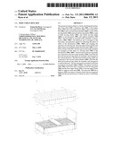 | 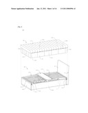 |
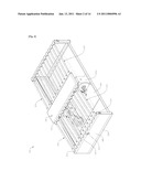 | 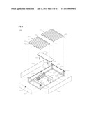 |
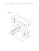 | 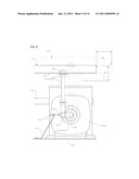 |
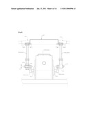 | 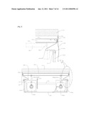 |
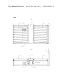 | 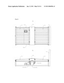 |
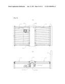 | 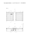 |
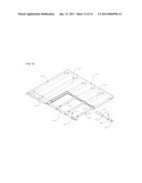 | 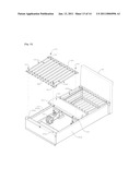 |
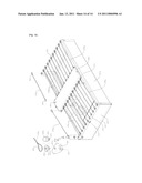 |  |
| Similar patent applications: | |
| Date | Title |
|---|---|
| 2014-08-21 | Bedbug infestation-resistant bed |
| New patent applications in this class: | |
| Date | Title |
|---|---|
| 2016-06-23 | Retainer bar assembly |
| 2016-06-16 | Heating and cooling sleeping system |
| 2016-05-26 | Tabletop sections for surgical tables |
| 2016-05-12 | Wheelchair bed insert device |
| 2016-05-12 | Armrest locking mechanism and integrated bed having same |
| Top Inventors for class "Beds" | |
| Rank | Inventor's name |
|---|---|
| 1 | Roger P. Jackson |
| 2 | David W. Hornbach |
| 3 | Richard H. Heimbrock |
| 4 | Jonathan D. Turner |
| 5 | Robert M. Zerhusen |