Patent application title: DEVICE FOR POSITIONING COMPONENTS
Inventors:
Josef Kipping (Schmelz, DE)
Rudiger Schütz (Schmelz, DE)
Rudiger Schütz (Schmelz, DE)
Rudiger Schütz (Schmelz, DE)
Rudiger Schütz (Schmelz, DE)
IPC8 Class: AB25B120FI
USPC Class:
269 45
Class name: Work holders plural holders to hold workpieces relative to each other with means to relatively array or arrange holders
Publication date: 2010-12-23
Patent application number: 20100320667
Inventors list |
Agents list |
Assignees list |
List by place |
Classification tree browser |
Top 100 Inventors |
Top 100 Agents |
Top 100 Assignees |
Usenet FAQ Index |
Documents |
Other FAQs |
Patent application title: DEVICE FOR POSITIONING COMPONENTS
Inventors:
Josef Kipping
Rudiger Schutz
Agents:
MCGLEW & TUTTLE, PC
Assignees:
Origin: SCARBOROUGH, NY US
IPC8 Class: AB25B120FI
USPC Class:
Publication date: 12/23/2010
Patent application number: 20100320667
Abstract:
A device for positioning components, in particular for use in bodymaking
of the motor vehicle industry, is provided with a rotatable receiving
plate (1) for the components and a drive device for turning the receiving
plate (1) about an axis of rotation (18), preferably arranged
perpendicularly in relation to the plane of the receiving plate (1). A
drive device is provided with a toggle clamping device (5) known per se,
wherein a linear drive (6) is connected via a toggle lever to a swivel
pin (16). The swivel pin (16) is positively and/or non-positively
connected via a receptacle (15) to the receiving plate (1) and provides
an adjustable swivelling movement of the receiving plate (1) into a
locked, advanced end position.Claims:
1. A device for positioning components, for use in bodymaking of the motor
vehicle industry, the device comprising:a rotatable receiving plate for
the components; anda drive device for turning the receiving plate about
an axis of rotation, the drive being arranged perpendicularly in relation
to the plane of the receiving plate, the drive device comprising a toggle
clamping device and a linear drive connected via a toggle lever to a
swivel pin and the swivel pin is positively and/or non-positively
connected via a receptacle to the receiving plate and provides an
adjustable swivelling movement of the receiving plate into a locked,
advanced end position.
2. A device as defined in claim 1, wherein the receiving plate can be swivelled about an angle of 1.degree. to 135.degree..
3. A device as defined in claim 1, wherein the toggle clamping device is mounted by means of clamping bolt in a partly open casing of the device in a detachable arrangement.
4. A device as defined in claim 1, wherein the swivel pin is profiled or configured as a square bolt and can be brought into an appropriate receptacle to enable power transmission.
5. A device as defined in claim 1, wherein the receiving plate is supported in a cross roller bearing.
6. A device as defined in claim 1, wherein the swivelling movement of said receiving plate is infinitely adjustable by varying the stroke of said linear drive.
7. A device as defined in claim 2, wherein the toggle clamping device is mounted by means of clamping bolt in a partly open casing of the device in a detachable arrangement.
8. A device as defined in claim 2, wherein the swivel pin is profiled or configured as a square bolt and can be brought into an appropriate receptacle to enable power transmission.
9. A device as defined in claim 3, wherein the swivel pin is profiled or configured as a square bolt and can be brought into an appropriate receptacle to enable power transmission.
Description:
CROSS REFERENCE TO RELATED APPLICATIONS
[0001]This application is a United States National Phase application of International Application PCT/EP2007/009292 and claims the benefit of priority under 35 U.S.C. §119 of German Patent Application DE 10 2006 055 103.6 filed Nov. 21, 2006, the entire contents of which are incorporated herein by reference.
FIELD OF THE INVENTION
[0002]The invention relates to a device for positioning components, in particular for use in bodymaking of the motor vehicle industry, with a rotatable receiving plate for the components and a drive device for turning the receiving plate about an axis of rotation, preferably arranged perpendicularly in relation to the plane of the receiving plate.
BACKGROUND OF THE INVENTION
[0003]In motor vehicle industry, rotating and swivelling devices are often needed to handle and to machine various components, particularly for assembly of various components, by way of which certain work pieces and components are brought into a machining and/or assembly position. For example, these devices can be manually turned into a distinct position and firmly positioned there, but they can also be swivelled to and fro, for example by means of pneumatic cylinders. However, specific pneumatic cylinders each having different strokes must be available to account for different swivelling angles.
[0004]DE 295 04 267 VI discloses an exemplary toggle clamping device in which a piston to be charged by pressure at both sides in alternating mode is guided in a longitudinally sliding arrangement within a cylinder to serve as linear drive and in which the piston rod at the free end within the casing of the toggle clamping device is connected to a toggle lever assembly which a clamping arm is assigned to. In particular, the toggle lever assembly is comprised of a swivelling pin supported within a casing and executing a rotating movement when the linear drive is actuated. The swivelling pin extends at a right angle to the longitudinal direction of the piston.
SUMMARY OF THE INVENTION
[0005]It is an object of the present invention to propose a device for positioning and swivelling of components about optionally adjustable swivelling angles that does not call for a frequent exchange of swivel drives.
[0006]To solve this task the drive device is comprised of a toggle clamping device known per se, wherein a linear drive is linked via a toggle lever to a swivelling pin and wherein the swivelling pin is positively or non-positively connected via a receptacle to a receiving plate and provides an adjustable swivelling movement of the receiving plate into a locked, advanced end position. Applying actually known toggle clamping devices as drive for defined swivelling movements of the receiving plate particularly bears the advantage that the components can be brought into an exactly positioned locked end position and that it is possible to adjust the swivelling angle in a simple manner at the linear drive of the toggle clamping device. Accordingly, it is in particular possible to adjust the angle infinitely, adjusting angles from 1° to 135°, preferably from 15° to 135°. Besides, the toggle clamping device also renders it possible to pick-up piston positions.
[0007]The actually known toggle clamping device is easy to connect in detachable arrangement by means of clamping bolts to the inventive device. Power transmission is preferably realized via an externally profiled swivelling pin, more particular via a square bolt, which is axially brought into an appropriate receptacle and maintained in the exact position via clamping bolts. The receptacle is directly or indirectly connected to the receiving plate, more particularly it is bolted, so that the receiving plate, too, is appropriately turned and/or swivelled on actuation of the linear drive in the toggle clamping device and on turning the swivelling pin. Preferably, a cross roller bearing is arranged between the stationary casing and the receiving plate.
[0008]The various features of novelty which characterize the invention are pointed out with particularity in the claims annexed to and forming a part of this disclosure. For a better understanding of the invention, its operating advantages and specific objects attained by its uses, reference is made to the accompanying drawings and descriptive matter in which preferred embodiments of the invention are illustrated.
BRIEF DESCRIPTION OF THE DRAWINGS
[0009]In the drawings:
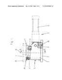
[0010]FIG. 1 is a side view of the inventive device;
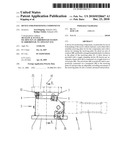
[0011]FIG. 2 is a top view of the device as per FIG. 1;
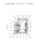
[0012]FIG. 3 is a section according line A-A of FIG. 1; and
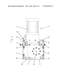
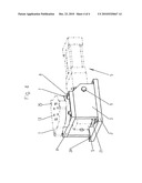
[0013]FIG. 4 is a perspective view of the inventive device.
DESCRIPTION OF THE PREFERRED EMBODIMENTS
[0014]Referring to the drawings in particular, The inventive receiving plate 1, which can be rotated and/or swivelled, is comprised of bores 25 to fasten components to be machined and/or mounted, with it being possible to bolt an actually known clamping bracket to said receiving plate 1. These clamping brackets then hold the relevant components. The casing of the inventive device is comprised of a base plate 2, side walls 3, and a covering plate 4, which are connected to each other by appropriate bolts 8 and 26. The actually known toggle lever clamping device 5 is brought from one side into this bilateral casing and exactly positioned and fixed by means of clamping bolts 9 and thrust plates 23. The toggle lever clamping device 5 is comprised of a linear drive 6 which is shown in FIGS. 1 and 2 in dashed lines only, said linear drive being moved clockwise and anti-clockwise in horizontal direction according to the views shown in FIGS. 1 and 2. Connected to said linear drive in an actually known manner is a toggle lever assembly not shown here, which swivel pins 16 supported in said toggle lever clamping device 5 belong to.
[0015]According to FIG. 3, said swivel pin 16 has a vertical rotating axis 18. It is profiled on its outside and more particularly it is designed and built as a square bolt which protrudes at its upper side into the receptacle 15 of the power transmission element 12 and connected there in a positively and non-positively locked manner to the power transmission element 12. The power transmission element 12, in turn, is connected via bolt 14 to the inner ring 11 of a cross roller bearing. This inner ring 11 is bolted through bolt 13 to the receiving plate 1, so that swivel pin 16, power transmission element 12, inner ring 11, and receiving plate 1 are firmly connected to each other and are rotated in the same manner. The outer ring 7 firmly connected by means of bolts 10 to cover plate 4 belongs to said inner ring 11. The lower section of FIG. 3 shows the lower end of swivel pin 16 which protrudes into an adapter sleeve 19 and which has a circular outer diameter and in which bearing 20 is guided which in turn is connected to the assembly plate 21. The assembly plate 21 is connected trough bolt 22 with base plate 2. Moreover, base plate 2 can be bolted through bores 24 to any arbitrary base not shown here.
[0016]While specific embodiments of the invention have been described in detail to illustrate the application of the principles of the invention, it will be understood that the invention may be embodied otherwise without departing from such principles.
User Contributions:
comments("1"); ?> comment_form("1"); ?>Inventors list |
Agents list |
Assignees list |
List by place |
Classification tree browser |
Top 100 Inventors |
Top 100 Agents |
Top 100 Assignees |
Usenet FAQ Index |
Documents |
Other FAQs |
User Contributions:
Comment about this patent or add new information about this topic:
| People who visited this patent also read: | |
| Patent application number | Title |
|---|---|
| 20220015019 | METHOD AND APPARATUS FOR PERFORMING INITIAL ACCESS IN LIMITED BANDWIDTH |
| 20220015018 | USER EQUIPMENT (UE) TRIGGERED EDGE COMPUTING APPLICATION CONTEXT RELOCATION |
| 20220015017 | Method for Quickly Searching for High-Rat Network, and Terminal Device |
| 20220015016 | MECHANISM TO PROVIDE UPDATES TO NB-IOT DEVICES |
| 20220015015 | METHOD AND APPARATUS FOR TRANSMITTING DOWNLINK CONTROL INFORMATION IN WIRELESS COMMUNICATION SYSTEM |
Images included with this patent application:
 |  |
 |  |
 |
| Similar patent applications: | |
| Date | Title |
|---|---|
| 2010-09-23 | Device for positioning workpiece |
| 2011-09-22 | Pin for positioning of parts made of composite material |
| 2008-11-20 | Gimbal mount device for supporting a functional element |
| 2008-09-18 | Device for the handling of containers |
| 2009-04-02 | Device for centring and clamping tubular parts |
| New patent applications in this class: | |
| Date | Title |
|---|---|
| 2016-12-29 | System and method for assembling tower sections of a wind turbine lattice tower structure |
| 2014-12-18 | Automatic truss jig setting system |
| 2014-11-20 | Pipe and tubing assembly workstation |
| 2014-01-02 | Interlocking clamp |
| 2013-10-17 | Wire holding device |
| New patent applications from these inventors: | |
| Date | Title |
|---|---|
| 2009-11-12 | Device for machining components, in particular of a vehicle body |
| 2009-05-21 | Device for machining components, in particular of a vehicle body |
| Top Inventors for class "Work holders" | |
| Rank | Inventor's name |
|---|---|
| 1 | Takayuki Kawakami |
| 2 | Chiaki Fukui |
| 3 | Kazuyoshi Takahashi |
| 4 | Hans Roesch |
| 5 | Bruce D. Mcintosh |