Patent application title: Transformer for RF Voltage Sensing
Inventors:
James W. Mcpherson (Boulder, CO, US)
Lewis Puterbaugh (Longmont, CO, US)
IPC8 Class: AA61B1818FI
USPC Class:
606 33
Class name: Instruments electrical application electromagnetic wave irradiation
Publication date: 2010-12-16
Patent application number: 20100318079
is disclosed. The electrosurgical system
includes a multiple-secondary transformer configured for sensing voltage.
The multiple-secondary transformer includes a primary winding coupled to
an active terminal and a return terminal of the electrosurgical system
and a plurality of secondary windings. Each of the secondary windings is
configured to transform the radio frequency voltage into a sensed
voltage. Each of the secondary windings includes an output coupled to a
sensor circuit and configured to transmit the sensed voltage to the
sensor circuit.Claims:
1. An electrosurgical generator, comprising:a radio frequency output stage
coupled to an active terminal and a return terminal and configured to
generate a radio frequency voltage;a sensor circuit that measures at
least one of a tissue property and a radio frequency voltage property;
anda multiple-secondary transformer including (i) a primary winding
having a first lead coupled to the active terminal and a second lead
coupled to the return terminal, the first and second leads coupled to the
radio frequency output stage and (ii) a plurality of secondary windings,
each including an output;wherein each of the secondary windings are
configured to transform the radio frequency voltage into a sensed voltage
and each of the outputs of the secondary windings are coupled to the
sensor circuit and configured to transmit the sensed voltage to the
sensor circuit.
2. The electrosurgical generator according to claim 1, wherein at least one of the plurality of secondary windings is modular and configured to be selectively engageable with the multiple-secondary transformer.
3. The electrosurgical generator according to claim 1, further comprising an electrosurgical instrument configured to deliver the radio frequency voltage to tissue, the electrosurgical instrument being coupled to the active terminal.
4. The electrosurgical generator according to claim 1, wherein the electrosurgical generator includes a plurality of outputs for interfacing with a plurality of monopolar and bipolar surgical instruments.
5. The electrosurgical generator according to claim 1, wherein the electrosurgical generator includes:a plurality of return electrodes configured to minimize tissue damage;a plurality of input controls for allowing a user to control the generator; andone or more displays for displaying output information.
6. The electrosurgical generator according to claim 1, wherein the radio frequency (RF) output stage is configured to generate sinusoidal waveforms of high RF energy.
7. The electrosurgical generator according to claim 1, wherein the radio frequency (RF) output stage is configured to generate a plurality of waveforms having different ranges of at least one of duty cycles, peak voltages, and crest factors.
8. The electrosurgical generator according to claim 1, wherein the radio frequency (RF) output stage is configured to generate:a 100% duty cycle sinusoidal waveform in a cut mode for ablating, fusing, and dissecting tissue; anda 1-25% duty cycle waveform in a coagulation mode for cauterizing tissue.
9. The electrosurgical generator according to claim 1, further comprising at least one sensing mechanism in operative communication with at least one feedback mechanism.
10. The electrosurgical generator according to claim 1, wherein the multiple-secondary transformer is configured to output multiple sense voltages.
11. A method for performing electrosurgery, the method comprising:providing a radio frequency output stage coupled to an active terminal and a return terminal;generating a radio frequency voltage via the radio frequency output stage;measuring at least one of a tissue property and a radio frequency voltage property via a sensor circuit; andproviding a multiple-secondary transformer including (i) a primary winding having a first lead coupled to the active terminal and a second lead coupled to the return terminal, the first and second leads coupled to the radio frequency output stage and (ii) a plurality of secondary windings, each including an output;wherein each of the secondary windings are configured to transform the radio frequency voltage into a sensed voltage and each of the outputs of the secondary windings are coupled to the sensor circuit and configured to transmit the sensed voltage to the sensor circuit.
12. The method according to claim 11,wherein at least one of the plurality of secondary windings steps down the radio frequency voltage; andwherein each of the plurality of secondary windings includes a same number of turns.
13. The method according to claim 11, wherein at least one of the plurality of secondary windings is modular and configured to be selectively engageable with the multiple-secondary transformer.
14. The method according to claim 11, further comprising the steps of:delivering the radio frequency voltage to tissue via the electrosurgical instrument coupled to the active terminal;allowing a user to control the generator via a plurality of input controls; anddisplaying output information via one or more displays.
15. The method according to claim 11, further comprising the steps of:providing a plurality of connectors to operatively cooperate with a plurality of surgical instruments; andswitching between the plurality of connectors via a switching mechanism.
16. The method according to claim 11, further comprising the step of providing a sensing mechanism to operatively communicate with a feedback mechanism.
17. The method according to claim 11, wherein the multiple-secondary transformer is configured to output multiple sense voltages.
18. A multiple-secondary transformer, comprising:a primary winding having a first lead coupled to the active terminal and a second lead coupled to the return terminal, the first and second leads coupled to the radio frequency output stage; anda plurality of secondary windings, each including an output;wherein each of the secondary windings are configured to transform radio frequency voltage into a sensed voltage and each of the outputs of the secondary windings are coupled to a sensor circuit and configured to transmit the sensed voltage to the sensor circuit.
19. The multiple-secondary transformer according to claim 18, wherein the multiple-secondary transformer operatively cooperates with a radio frequency output stage coupled to an active terminal and a return terminal and configured to generate the radio frequency voltage.
20. The multiple-secondary transformer according to claim 18, wherein the sensor circuit measures at least one of a tissue property and a radio frequency voltage property.Description:
CROSS-REFERENCE TO RELATED APPLICATIONS
[0001]This application is a continuation of U.S. patent application Ser. No. 11/529,416, filed on Sep. 28, 2006, the entire disclosure of which is incorporated by reference herein.
BACKGROUND
[0002]1. Technical Field
[0003]The present disclosure relates to electrosurgical apparatuses, systems and methods. More particularly, the present disclosure is directed to electrosurgical generators including a transformer configured for sensing voltage.
[0004]2. Background of Related Art
[0005]Energy-based tissue treatment is well known in the art. Various types of energy (e.g., electrical, ultrasonic, microwave, cryo, heat, laser, etc.) are applied to tissue to achieve a desired result. Electrosurgery involves application of high radio frequency electrical current to a surgical site to cut, ablate, coagulate or seal tissue. In monopolar electrosurgery, a source or active electrode delivers radio frequency energy from the electrosurgical generator to the tissue and a return electrode carries the current back to the generator. In monopolar electrosurgery, the source electrode is typically part of the surgical instrument held by the surgeon and applied to the tissue to be treated. A patient return electrode is placed remotely from the active electrode to carry the current back to the generator.
[0006]Ablation is most commonly a monopolar procedure that is particularly useful in the field of cancer treatment, where one or more RF ablation needle electrodes (usually of elongated cylindrical geometry) are inserted into a living body. A typical form of such needle electrodes incorporates an insulated sheath from which an exposed (uninsulated) tip extends. When an RF energy is provided between the return electrode and the inserted ablation electrode, RF current flows from the needle electrode through the body. Typically, the current density is very high near the tip of the needle electrode, which tends to heat and destroy surrounding issue.
[0007]In bipolar electrosurgery, one of the electrodes of the hand-held instrument functions as the active electrode and the other as the return electrode. The return electrode is placed in close proximity to the active electrode such that an electrical circuit is formed between the two electrodes (e.g., electrosurgical forceps). In this manner, the applied electrical current is limited to the body tissue positioned between the electrodes. When the electrodes are sufficiently separated from one another, the electrical circuit is open and thus inadvertent contact with body tissue with either of the separated electrodes does not cause current to flow.
[0008]It is known in the art that electrosurgical generators utilize transformers to sense voltage. However, conventional generators generally include one or more transformers performing redundant functions.
SUMMARY
[0009]The present disclosure relates to a multiple-secondary transformer for use in electrosurgical generators. The transformer includes one or more secondary windings allowing the transformer to output a corresponding number of sensed voltage signals to a sensor circuit for subsequent analysis.
[0010]According to one aspect of the present disclosure, an electrosurgical system is disclosed. The electrosurgical system includes a multiple-secondary transformer configured for sensing voltage. The multiple-secondary transformer includes a primary winding coupled to an active terminal and a return terminal of the electrosurgical system and a plurality of secondary windings. Each of the secondary windings is configured to transform the radio frequency voltage into a sensed voltage. Each of the secondary windings includes an output coupled to a sensor circuit and configured to transmit the sensed voltage to the sensor circuit.
[0011]According to another aspect of the present disclosure an electrosurgical generator is disclosed. The generator includes a radio frequency output stage having an active terminal and a return terminal and configured to generate a radio frequency voltage and a sensor circuit that measures at least one of a tissue property and a radio frequency voltage property. The generator also includes a multiple-secondary transformer having a primary winding coupled to an active terminal and a return terminal of the electrosurgical system and a plurality of secondary windings. Each of the secondary windings is configured to transform the radio frequency voltage into a sensed voltage. Each of the secondary windings includes an output coupled to a sensor circuit and configured to transmit the sensed voltage to the sensor circuit.
[0012]A method for is also contemplated by the present disclosure. The method includes the steps of providing a multiple-secondary transformer configured for sensing voltage. The multiple-secondary transformer includes a primary winding coupled to an active terminal and a return terminal of the electrosurgical system and a plurality of secondary windings. Each of the secondary windings includes an output coupled to a sensor circuit. The method also includes the steps of generating a radio frequency voltage at a radio frequency output stage including an active terminal and a return terminal and transforming the radio frequency voltage into a sensed voltage at each of the secondary windings and transmitting the sensed voltage to the sensor circuit via the output.
BRIEF DESCRIPTION OF THE DRAWINGS
[0013]Various embodiments of the present disclosure are described herein with reference to the drawings wherein:
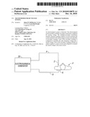
[0014]FIGS. 1A-1B are schematic block diagrams of an electrosurgical system according to the present disclosure;
[0015]FIG. 2 is a schematic block diagram of a generator according to one embodiment of the present disclosure; and
[0016]FIG. 3 is an electrical schematic diagram of a multiple-secondary transformer according to the present disclosure.
DETAILED DESCRIPTION
[0017]Particular embodiments of the present disclosure are described hereinbelow with reference to the accompanying drawings. In the following description, well-known functions or constructions are not described in detail to avoid obscuring the present disclosure in unnecessary detail.
[0018]The generator according to the present disclosure can perform monopolar and bipolar electrosurgical procedures, including vessel sealing procedures. The generator may include a plurality of outputs for interfacing with various electrosurgical instruments (e.g., a monopolar active electrode, return electrode, bipolar electrosurgical forceps, footswitch, etc.). Further, the generator includes electronic circuitry configured for generating radio frequency power specifically suited for various electrosurgical modes (e.g., cutting, blending, division, etc.) and procedures (e.g., monopolar, bipolar, vessel sealing).
[0019]FIG. 1A is a schematic illustration of a monopolar electrosurgical system according to one embodiment of the present disclosure. The system includes an electrosurgical instrument 2 having one or more electrodes for treating tissue of a patient P. The instrument 2 is a monopolar type instrument including one or more active electrodes (e.g., electrosurgical cutting probe, ablation electrode(s), etc.). Electrosurgical RF energy is supplied to the instrument 2 by a generator 20 via an supply line 4, which is connected to an active terminal 30 (FIG. 2) of the generator 20, allowing the instrument 2 to coagulate, seal, ablate and/or otherwise treat tissue. The energy is returned to the generator 20 through a return electrode 6 via a return line 8 at a return terminal 32 (FIG. 2) of the generator 20. The active terminal 30 and the return terminal 32 are connectors configured to interface with plugs (not explicitly shown) of the instrument 2 and the return electrode 6, which are disposed at the ends of the supply line 4 and the return line 8 respectively.
[0020]The system may include a plurality of return electrodes 6 that are arranged to minimize the chances of tissue damage by maximizing the overall contact area with the patient P. In addition, the generator 20 and the return electrode 6 may be configured for monitoring so-called "tissue-to-patient" contact to insure that sufficient contact exists therebetween to further minimize chances of tissue damage.
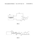
[0021]FIG. 1B is a schematic illustration of a bipolar electrosurgical system according to the present disclosure. The system includes a bipolar electrosurgical forceps 10 having one or more electrodes for treating tissue of a patient P. The electrosurgical forceps 10 include opposing jaw members having an active electrode 14 and a return electrode 16 disposed therein. The active electrode 14 and the return electrode 16 are connected to the generator 20 through cable 18, which includes the supply and return lines 4, 8 coupled to the active and return terminals 30, 32, respectively (FIG. 2). The electrosurgical forceps 10 are coupled to the generator 20 at a connector 21 having connections to the active and return terminals 30 and 32 (e.g., pins) via a plug disposed at the end of the cable 18, wherein the plug includes contacts from the supply and return lines 4, 8.
[0022]The generator 20 includes suitable input controls (e.g., buttons, activators, switches, touch screen, etc.) for controlling the generator 20. In addition, the generator 20 may include one or more display screens for providing the user with variety of output information (e.g., intensity settings, treatment complete indicators, etc.). The controls allow the user to adjust power of the RF energy, waveform, and other parameters to achieve the desired waveform suitable for a particular task (e.g., coagulating, tissue sealing, intensity setting, etc.). The instrument 2 may also include a plurality of input controls that may be redundant with certain input controls of the generator 20. Placing the input controls at the instrument 2 allows for easier and faster modification of RF energy parameters during the surgical procedure without requiring interaction with the generator 20.
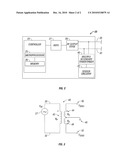
[0023]FIG. 2 shows a schematic block diagram of the generator 20 having a controller 24, a high voltage DC power supply 27 ("HVPS") and an RF output stage 28. The HVPS 27 is connected to a conventional AC source (e.g., electrical wall outlet) and provides high voltage DC power to an RF output stage 28, which then converts high voltage DC power into RF energy and delivers the RF energy to the active terminal 30. The energy is returned thereto via the return terminal 32.
[0024]In particular, the RF output stage 28 generates sinusoidal waveforms of high RF energy. The RF output stage 28 is configured to generate a plurality of waveforms having various duty cycles, peak voltages, crest factors, and other suitable parameters. Certain types of waveforms are suitable for specific electrosurgical modes. For instance, the RF output stage 28 generates a 100% duty cycle sinusoidal waveform in cut mode, which is best suited for ablating, fusing and dissecting tissue and a 1-25% duty cycle waveform in coagulation mode, which is best used for cauterizing tissue to stop bleeding.
[0025]The generator 20 may include a plurality of connectors to accommodate various types of electrosurgical instruments (e.g., instrument 2, electrosurgical forceps 10, etc.). Further, the generator 20 is configured to operate in a variety of modes such as ablation, monopolar and bipolar cutting coagulation, etc. It is envisioned that the generator 20 may include a switching mechanism (e.g., relays) to switch the supply of RF energy between the connectors, such that, for instance, when the instrument 2 is connected to the generator 20, only the monopolar plug receives RF energy.
[0026]The controller 24 includes a microprocessor 25 operably connected to a memory 26, which may be volatile type memory (e.g., RAM) and/or non-volatile type memory (e.g., flash media, disk media, etc.). The microprocessor 25 includes an output port that is operably connected to the HVPS 27 and/or RF output stage 28 allowing the microprocessor 25 to control the output of the generator 20 according to either open and/or closed control loop schemes. Those skilled in the art will appreciate that the microprocessor 25 may be substituted by any logic processor (e.g., control circuit) adapted to perform the calculations discussed herein.
[0027]A closed loop control scheme is a feedback control loop wherein sensor circuit 22, which may include a plurality of sensors measuring a variety of tissue and energy properties (e.g., tissue impedance, tissue temperature, output current and/or voltage, etc.), provides feedback to the controller 24. Such sensors are within the purview of those skilled in the art. The controller 24 then signals the HVPS 27 and/or RF output stage 28, which then adjust DC and/or RF power supply, respectively. The controller 24 also receives input signals from the input controls of the generator 20 or the instrument 2. The controller 24 utilizes the input signals to adjust power outputted by the generator 20 and/or performs other control functions thereon.
[0028]In various types of control loops it may be desirable to measure certain properties of RF energy being delivered by the RF output stage 28. In particular, voltage is continuously measured and delivered to the sensor circuit 22 (e.g., calculating impedance at the surgical site). A multiple-secondary transformer 40 is coupled between the RF output stage 28 and the active and return terminals 30, 32. The transformer 40 provides voltage signals to the sensor circuit 22. In conventional generators, multiple sense transformers are used to serve as voltage sensors for multiple purposes, such as primary voltage sense (e.g., calculating tissue and RF energy properties) and secondary voltage sense (e.g. dosage error calculation, single fault protection). In contrast, the transformer 40, according to the teachings of one embodiment of the present disclosure, is configured to output multiple sense voltages obviating the need for multiple sense transformers.
[0029]FIG. 3 shows an electrical schematic diagram of the transformer 40 coupled to the active and return terminals 30 and 32 of the RF output stage 27. The RF output stage 27 generates a radio frequency voltage (VRF) suitable for performing electrosurgical procedures (e.g., coagulation, ablation, etc.). The transformer 40 transforms the VRF to desired sensed voltage, in particular, the sensed voltages VSEN1 and VSEN2. The transformer 40 includes a primary winding 42, which is in circuit with the output of the RF output stage 27, and a plurality of secondary windings 44 and 46 in circuit with sensor circuit outputs 50 and 52 respectively. The transformer 40 is also connected to a sensor circuit return 48, which serves as a ground connection. The transformer 40 may be also configured for differential measurement thereby obviating the need for a ground connection. Having multiple secondary windings allows the transformer 40 to output multiple VSEN voltages to the sensor circuit 22. Thus, VSEN1 may be used as primary sensed voltage for determining impedance of the tissue and VSEN2 may be used as secondary sensed voltage for monitoring various error conditions.
[0030]The primary winding 42 includes a predetermined number of primary turns NP and the secondary windings 44 and 46 include a number of secondary turns NS. If NS is the same for each of the secondary windings 44 and 46, the turns ratio (NP/NS), which determines the step-down ratio of the transformer 40, is also the same. This allows the transformer 40 to output equivalent VSEN1 and VSEN2 for a uniform VRF. Ns may be different for each of the secondary circuits 44 and 46 allowing for different step-down ratios and, hence, different VSEN.
[0031]The transformer 40 may include multiple secondary windings (e.g., three or four) depending on the number of sensed voltages to be monitored by the sensor circuit 22. The secondary circuits of the transformer 40 may be modular, such that the secondary winding can be switched "in" and "out" to adjust the step down ration. This will accommodate large variation in RF voltages related to different generator modes.
[0032]The transformer 40 provides for many improvements over conventional electrosurgical transformers, such as better coupling due to a single transformer core. Single core configuration also improves accuracy related to dosage errors and provide for a more compact. This in turn reduces the foot print of the circuit as well as the overall mass of the generator 20. A more simplified design also provides for cheaper construction of the generator 20 since a single transformer can perform the same function which was previously performed by multiple transformers.
[0033]While several embodiments of the disclosure have been shown in the drawings and/or discussed herein, it is not intended that the disclosure be limited thereto, as it is intended that the disclosure be as broad in scope as the art will allow and that the specification be read likewise. Therefore, the above description should not be construed as limiting, but merely as exemplifications of particular embodiments. Those skilled in the art will envision other modifications within the scope and spirit of the claims appended hereto.
Claims:
1. An electrosurgical generator, comprising:a radio frequency output stage
coupled to an active terminal and a return terminal and configured to
generate a radio frequency voltage;a sensor circuit that measures at
least one of a tissue property and a radio frequency voltage property;
anda multiple-secondary transformer including (i) a primary winding
having a first lead coupled to the active terminal and a second lead
coupled to the return terminal, the first and second leads coupled to the
radio frequency output stage and (ii) a plurality of secondary windings,
each including an output;wherein each of the secondary windings are
configured to transform the radio frequency voltage into a sensed voltage
and each of the outputs of the secondary windings are coupled to the
sensor circuit and configured to transmit the sensed voltage to the
sensor circuit.
2. The electrosurgical generator according to claim 1, wherein at least one of the plurality of secondary windings is modular and configured to be selectively engageable with the multiple-secondary transformer.
3. The electrosurgical generator according to claim 1, further comprising an electrosurgical instrument configured to deliver the radio frequency voltage to tissue, the electrosurgical instrument being coupled to the active terminal.
4. The electrosurgical generator according to claim 1, wherein the electrosurgical generator includes a plurality of outputs for interfacing with a plurality of monopolar and bipolar surgical instruments.
5. The electrosurgical generator according to claim 1, wherein the electrosurgical generator includes:a plurality of return electrodes configured to minimize tissue damage;a plurality of input controls for allowing a user to control the generator; andone or more displays for displaying output information.
6. The electrosurgical generator according to claim 1, wherein the radio frequency (RF) output stage is configured to generate sinusoidal waveforms of high RF energy.
7. The electrosurgical generator according to claim 1, wherein the radio frequency (RF) output stage is configured to generate a plurality of waveforms having different ranges of at least one of duty cycles, peak voltages, and crest factors.
8. The electrosurgical generator according to claim 1, wherein the radio frequency (RF) output stage is configured to generate:a 100% duty cycle sinusoidal waveform in a cut mode for ablating, fusing, and dissecting tissue; anda 1-25% duty cycle waveform in a coagulation mode for cauterizing tissue.
9. The electrosurgical generator according to claim 1, further comprising at least one sensing mechanism in operative communication with at least one feedback mechanism.
10. The electrosurgical generator according to claim 1, wherein the multiple-secondary transformer is configured to output multiple sense voltages.
11. A method for performing electrosurgery, the method comprising:providing a radio frequency output stage coupled to an active terminal and a return terminal;generating a radio frequency voltage via the radio frequency output stage;measuring at least one of a tissue property and a radio frequency voltage property via a sensor circuit; andproviding a multiple-secondary transformer including (i) a primary winding having a first lead coupled to the active terminal and a second lead coupled to the return terminal, the first and second leads coupled to the radio frequency output stage and (ii) a plurality of secondary windings, each including an output;wherein each of the secondary windings are configured to transform the radio frequency voltage into a sensed voltage and each of the outputs of the secondary windings are coupled to the sensor circuit and configured to transmit the sensed voltage to the sensor circuit.
12. The method according to claim 11,wherein at least one of the plurality of secondary windings steps down the radio frequency voltage; andwherein each of the plurality of secondary windings includes a same number of turns.
13. The method according to claim 11, wherein at least one of the plurality of secondary windings is modular and configured to be selectively engageable with the multiple-secondary transformer.
14. The method according to claim 11, further comprising the steps of:delivering the radio frequency voltage to tissue via the electrosurgical instrument coupled to the active terminal;allowing a user to control the generator via a plurality of input controls; anddisplaying output information via one or more displays.
15. The method according to claim 11, further comprising the steps of:providing a plurality of connectors to operatively cooperate with a plurality of surgical instruments; andswitching between the plurality of connectors via a switching mechanism.
16. The method according to claim 11, further comprising the step of providing a sensing mechanism to operatively communicate with a feedback mechanism.
17. The method according to claim 11, wherein the multiple-secondary transformer is configured to output multiple sense voltages.
18. A multiple-secondary transformer, comprising:a primary winding having a first lead coupled to the active terminal and a second lead coupled to the return terminal, the first and second leads coupled to the radio frequency output stage; anda plurality of secondary windings, each including an output;wherein each of the secondary windings are configured to transform radio frequency voltage into a sensed voltage and each of the outputs of the secondary windings are coupled to a sensor circuit and configured to transmit the sensed voltage to the sensor circuit.
19. The multiple-secondary transformer according to claim 18, wherein the multiple-secondary transformer operatively cooperates with a radio frequency output stage coupled to an active terminal and a return terminal and configured to generate the radio frequency voltage.
20. The multiple-secondary transformer according to claim 18, wherein the sensor circuit measures at least one of a tissue property and a radio frequency voltage property.
Description:
CROSS-REFERENCE TO RELATED APPLICATIONS
[0001]This application is a continuation of U.S. patent application Ser. No. 11/529,416, filed on Sep. 28, 2006, the entire disclosure of which is incorporated by reference herein.
BACKGROUND
[0002]1. Technical Field
[0003]The present disclosure relates to electrosurgical apparatuses, systems and methods. More particularly, the present disclosure is directed to electrosurgical generators including a transformer configured for sensing voltage.
[0004]2. Background of Related Art
[0005]Energy-based tissue treatment is well known in the art. Various types of energy (e.g., electrical, ultrasonic, microwave, cryo, heat, laser, etc.) are applied to tissue to achieve a desired result. Electrosurgery involves application of high radio frequency electrical current to a surgical site to cut, ablate, coagulate or seal tissue. In monopolar electrosurgery, a source or active electrode delivers radio frequency energy from the electrosurgical generator to the tissue and a return electrode carries the current back to the generator. In monopolar electrosurgery, the source electrode is typically part of the surgical instrument held by the surgeon and applied to the tissue to be treated. A patient return electrode is placed remotely from the active electrode to carry the current back to the generator.
[0006]Ablation is most commonly a monopolar procedure that is particularly useful in the field of cancer treatment, where one or more RF ablation needle electrodes (usually of elongated cylindrical geometry) are inserted into a living body. A typical form of such needle electrodes incorporates an insulated sheath from which an exposed (uninsulated) tip extends. When an RF energy is provided between the return electrode and the inserted ablation electrode, RF current flows from the needle electrode through the body. Typically, the current density is very high near the tip of the needle electrode, which tends to heat and destroy surrounding issue.
[0007]In bipolar electrosurgery, one of the electrodes of the hand-held instrument functions as the active electrode and the other as the return electrode. The return electrode is placed in close proximity to the active electrode such that an electrical circuit is formed between the two electrodes (e.g., electrosurgical forceps). In this manner, the applied electrical current is limited to the body tissue positioned between the electrodes. When the electrodes are sufficiently separated from one another, the electrical circuit is open and thus inadvertent contact with body tissue with either of the separated electrodes does not cause current to flow.
[0008]It is known in the art that electrosurgical generators utilize transformers to sense voltage. However, conventional generators generally include one or more transformers performing redundant functions.
SUMMARY
[0009]The present disclosure relates to a multiple-secondary transformer for use in electrosurgical generators. The transformer includes one or more secondary windings allowing the transformer to output a corresponding number of sensed voltage signals to a sensor circuit for subsequent analysis.
[0010]According to one aspect of the present disclosure, an electrosurgical system is disclosed. The electrosurgical system includes a multiple-secondary transformer configured for sensing voltage. The multiple-secondary transformer includes a primary winding coupled to an active terminal and a return terminal of the electrosurgical system and a plurality of secondary windings. Each of the secondary windings is configured to transform the radio frequency voltage into a sensed voltage. Each of the secondary windings includes an output coupled to a sensor circuit and configured to transmit the sensed voltage to the sensor circuit.
[0011]According to another aspect of the present disclosure an electrosurgical generator is disclosed. The generator includes a radio frequency output stage having an active terminal and a return terminal and configured to generate a radio frequency voltage and a sensor circuit that measures at least one of a tissue property and a radio frequency voltage property. The generator also includes a multiple-secondary transformer having a primary winding coupled to an active terminal and a return terminal of the electrosurgical system and a plurality of secondary windings. Each of the secondary windings is configured to transform the radio frequency voltage into a sensed voltage. Each of the secondary windings includes an output coupled to a sensor circuit and configured to transmit the sensed voltage to the sensor circuit.
[0012]A method for is also contemplated by the present disclosure. The method includes the steps of providing a multiple-secondary transformer configured for sensing voltage. The multiple-secondary transformer includes a primary winding coupled to an active terminal and a return terminal of the electrosurgical system and a plurality of secondary windings. Each of the secondary windings includes an output coupled to a sensor circuit. The method also includes the steps of generating a radio frequency voltage at a radio frequency output stage including an active terminal and a return terminal and transforming the radio frequency voltage into a sensed voltage at each of the secondary windings and transmitting the sensed voltage to the sensor circuit via the output.
BRIEF DESCRIPTION OF THE DRAWINGS
[0013]Various embodiments of the present disclosure are described herein with reference to the drawings wherein:
[0014]FIGS. 1A-1B are schematic block diagrams of an electrosurgical system according to the present disclosure;
[0015]FIG. 2 is a schematic block diagram of a generator according to one embodiment of the present disclosure; and
[0016]FIG. 3 is an electrical schematic diagram of a multiple-secondary transformer according to the present disclosure.
DETAILED DESCRIPTION
[0017]Particular embodiments of the present disclosure are described hereinbelow with reference to the accompanying drawings. In the following description, well-known functions or constructions are not described in detail to avoid obscuring the present disclosure in unnecessary detail.
[0018]The generator according to the present disclosure can perform monopolar and bipolar electrosurgical procedures, including vessel sealing procedures. The generator may include a plurality of outputs for interfacing with various electrosurgical instruments (e.g., a monopolar active electrode, return electrode, bipolar electrosurgical forceps, footswitch, etc.). Further, the generator includes electronic circuitry configured for generating radio frequency power specifically suited for various electrosurgical modes (e.g., cutting, blending, division, etc.) and procedures (e.g., monopolar, bipolar, vessel sealing).
[0019]FIG. 1A is a schematic illustration of a monopolar electrosurgical system according to one embodiment of the present disclosure. The system includes an electrosurgical instrument 2 having one or more electrodes for treating tissue of a patient P. The instrument 2 is a monopolar type instrument including one or more active electrodes (e.g., electrosurgical cutting probe, ablation electrode(s), etc.). Electrosurgical RF energy is supplied to the instrument 2 by a generator 20 via an supply line 4, which is connected to an active terminal 30 (FIG. 2) of the generator 20, allowing the instrument 2 to coagulate, seal, ablate and/or otherwise treat tissue. The energy is returned to the generator 20 through a return electrode 6 via a return line 8 at a return terminal 32 (FIG. 2) of the generator 20. The active terminal 30 and the return terminal 32 are connectors configured to interface with plugs (not explicitly shown) of the instrument 2 and the return electrode 6, which are disposed at the ends of the supply line 4 and the return line 8 respectively.
[0020]The system may include a plurality of return electrodes 6 that are arranged to minimize the chances of tissue damage by maximizing the overall contact area with the patient P. In addition, the generator 20 and the return electrode 6 may be configured for monitoring so-called "tissue-to-patient" contact to insure that sufficient contact exists therebetween to further minimize chances of tissue damage.
[0021]FIG. 1B is a schematic illustration of a bipolar electrosurgical system according to the present disclosure. The system includes a bipolar electrosurgical forceps 10 having one or more electrodes for treating tissue of a patient P. The electrosurgical forceps 10 include opposing jaw members having an active electrode 14 and a return electrode 16 disposed therein. The active electrode 14 and the return electrode 16 are connected to the generator 20 through cable 18, which includes the supply and return lines 4, 8 coupled to the active and return terminals 30, 32, respectively (FIG. 2). The electrosurgical forceps 10 are coupled to the generator 20 at a connector 21 having connections to the active and return terminals 30 and 32 (e.g., pins) via a plug disposed at the end of the cable 18, wherein the plug includes contacts from the supply and return lines 4, 8.
[0022]The generator 20 includes suitable input controls (e.g., buttons, activators, switches, touch screen, etc.) for controlling the generator 20. In addition, the generator 20 may include one or more display screens for providing the user with variety of output information (e.g., intensity settings, treatment complete indicators, etc.). The controls allow the user to adjust power of the RF energy, waveform, and other parameters to achieve the desired waveform suitable for a particular task (e.g., coagulating, tissue sealing, intensity setting, etc.). The instrument 2 may also include a plurality of input controls that may be redundant with certain input controls of the generator 20. Placing the input controls at the instrument 2 allows for easier and faster modification of RF energy parameters during the surgical procedure without requiring interaction with the generator 20.
[0023]FIG. 2 shows a schematic block diagram of the generator 20 having a controller 24, a high voltage DC power supply 27 ("HVPS") and an RF output stage 28. The HVPS 27 is connected to a conventional AC source (e.g., electrical wall outlet) and provides high voltage DC power to an RF output stage 28, which then converts high voltage DC power into RF energy and delivers the RF energy to the active terminal 30. The energy is returned thereto via the return terminal 32.
[0024]In particular, the RF output stage 28 generates sinusoidal waveforms of high RF energy. The RF output stage 28 is configured to generate a plurality of waveforms having various duty cycles, peak voltages, crest factors, and other suitable parameters. Certain types of waveforms are suitable for specific electrosurgical modes. For instance, the RF output stage 28 generates a 100% duty cycle sinusoidal waveform in cut mode, which is best suited for ablating, fusing and dissecting tissue and a 1-25% duty cycle waveform in coagulation mode, which is best used for cauterizing tissue to stop bleeding.
[0025]The generator 20 may include a plurality of connectors to accommodate various types of electrosurgical instruments (e.g., instrument 2, electrosurgical forceps 10, etc.). Further, the generator 20 is configured to operate in a variety of modes such as ablation, monopolar and bipolar cutting coagulation, etc. It is envisioned that the generator 20 may include a switching mechanism (e.g., relays) to switch the supply of RF energy between the connectors, such that, for instance, when the instrument 2 is connected to the generator 20, only the monopolar plug receives RF energy.
[0026]The controller 24 includes a microprocessor 25 operably connected to a memory 26, which may be volatile type memory (e.g., RAM) and/or non-volatile type memory (e.g., flash media, disk media, etc.). The microprocessor 25 includes an output port that is operably connected to the HVPS 27 and/or RF output stage 28 allowing the microprocessor 25 to control the output of the generator 20 according to either open and/or closed control loop schemes. Those skilled in the art will appreciate that the microprocessor 25 may be substituted by any logic processor (e.g., control circuit) adapted to perform the calculations discussed herein.
[0027]A closed loop control scheme is a feedback control loop wherein sensor circuit 22, which may include a plurality of sensors measuring a variety of tissue and energy properties (e.g., tissue impedance, tissue temperature, output current and/or voltage, etc.), provides feedback to the controller 24. Such sensors are within the purview of those skilled in the art. The controller 24 then signals the HVPS 27 and/or RF output stage 28, which then adjust DC and/or RF power supply, respectively. The controller 24 also receives input signals from the input controls of the generator 20 or the instrument 2. The controller 24 utilizes the input signals to adjust power outputted by the generator 20 and/or performs other control functions thereon.
[0028]In various types of control loops it may be desirable to measure certain properties of RF energy being delivered by the RF output stage 28. In particular, voltage is continuously measured and delivered to the sensor circuit 22 (e.g., calculating impedance at the surgical site). A multiple-secondary transformer 40 is coupled between the RF output stage 28 and the active and return terminals 30, 32. The transformer 40 provides voltage signals to the sensor circuit 22. In conventional generators, multiple sense transformers are used to serve as voltage sensors for multiple purposes, such as primary voltage sense (e.g., calculating tissue and RF energy properties) and secondary voltage sense (e.g. dosage error calculation, single fault protection). In contrast, the transformer 40, according to the teachings of one embodiment of the present disclosure, is configured to output multiple sense voltages obviating the need for multiple sense transformers.
[0029]FIG. 3 shows an electrical schematic diagram of the transformer 40 coupled to the active and return terminals 30 and 32 of the RF output stage 27. The RF output stage 27 generates a radio frequency voltage (VRF) suitable for performing electrosurgical procedures (e.g., coagulation, ablation, etc.). The transformer 40 transforms the VRF to desired sensed voltage, in particular, the sensed voltages VSEN1 and VSEN2. The transformer 40 includes a primary winding 42, which is in circuit with the output of the RF output stage 27, and a plurality of secondary windings 44 and 46 in circuit with sensor circuit outputs 50 and 52 respectively. The transformer 40 is also connected to a sensor circuit return 48, which serves as a ground connection. The transformer 40 may be also configured for differential measurement thereby obviating the need for a ground connection. Having multiple secondary windings allows the transformer 40 to output multiple VSEN voltages to the sensor circuit 22. Thus, VSEN1 may be used as primary sensed voltage for determining impedance of the tissue and VSEN2 may be used as secondary sensed voltage for monitoring various error conditions.
[0030]The primary winding 42 includes a predetermined number of primary turns NP and the secondary windings 44 and 46 include a number of secondary turns NS. If NS is the same for each of the secondary windings 44 and 46, the turns ratio (NP/NS), which determines the step-down ratio of the transformer 40, is also the same. This allows the transformer 40 to output equivalent VSEN1 and VSEN2 for a uniform VRF. Ns may be different for each of the secondary circuits 44 and 46 allowing for different step-down ratios and, hence, different VSEN.
[0031]The transformer 40 may include multiple secondary windings (e.g., three or four) depending on the number of sensed voltages to be monitored by the sensor circuit 22. The secondary circuits of the transformer 40 may be modular, such that the secondary winding can be switched "in" and "out" to adjust the step down ration. This will accommodate large variation in RF voltages related to different generator modes.
[0032]The transformer 40 provides for many improvements over conventional electrosurgical transformers, such as better coupling due to a single transformer core. Single core configuration also improves accuracy related to dosage errors and provide for a more compact. This in turn reduces the foot print of the circuit as well as the overall mass of the generator 20. A more simplified design also provides for cheaper construction of the generator 20 since a single transformer can perform the same function which was previously performed by multiple transformers.
[0033]While several embodiments of the disclosure have been shown in the drawings and/or discussed herein, it is not intended that the disclosure be limited thereto, as it is intended that the disclosure be as broad in scope as the art will allow and that the specification be read likewise. Therefore, the above description should not be construed as limiting, but merely as exemplifications of particular embodiments. Those skilled in the art will envision other modifications within the scope and spirit of the claims appended hereto.
User Contributions:
Comment about this patent or add new information about this topic:
| People who visited this patent also read: | |
| Patent application number | Title |
|---|---|
| 20200169527 | MULTIPLE LINK LAYER ADDRESS RESOLUTION PROTOCOL (ARP) |
| 20200169526 | METHODS FOR MANAGING SHARING AND FOR SHARING MESSAGES, MESSAGING DEVICES OF DISTINCT TYPES IMPLEMENTING SAME |
| 20200169525 | AUTOMATIC RESPONSE SYSTEM BASED ON BODY LANGUAGE |
| 20200169524 | APPARATUS, SYSTEM, AND METHOD OF ELASTICALLY PROCESSING MESSAGE INFORMATION FROM MULTIPLE SOURCES |
| 20200169523 | ARTIFICIAL INTELLIGENT SYSTEMS AND METHODS FOR PRESENTING A PROMPTING MESSAGE ON A MOBILE DEVICE |
Images included with this patent application:
 |  |
 |
| Similar patent applications: | |
| Date | Title |
|---|---|
| 2010-11-18 | Sterile barrier for a surgical robot with torque sensors |
| 2009-09-24 | Universal extractor for total endoprostheses of (tep) of the knee joint |
| 2011-02-17 | Instruments and methods for minimally invasive spine surgery |
| 2009-01-15 | Stripping device for removal of varicose veins |
| 2009-05-07 | Instrument for guiding stage apparatus and method for using same |
| New patent applications in this class: | |
| Date | Title |
|---|---|
| 2017-08-17 | Microwave ablation antenna assemblies |
| 2017-08-17 | Systems and methods for determining the status of a fluid-cooled microwave ablation system |
| 2016-12-29 | Electrosurgical apparatus for generating radiofrequency energy and microwave energy for delivery into biological tissue |
| 2016-12-29 | Ablation device with sensor |
| 2016-09-01 | Microwave antenna assembly and method of using the same |
| New patent applications from these inventors: | |
| Date | Title |
|---|---|
| 2016-02-11 | External reader for device management |
| 2015-05-21 | Energy-harvesting system, apparatus and methods |
| 2015-05-14 | Switched resonant ultrasonic power amplifier system |
| 2014-08-28 | Systems and devices for treatment of hypothermia and systems including garments adapted to controllably emit energy for warming wearer |
| 2014-06-12 | Switched resonant ultrasonic power amplifier system |
| Top Inventors for class "Surgery" | |
| Rank | Inventor's name |
|---|---|
| 1 | Lutz Biedermann |
| 2 | Roger P. Jackson |
| 3 | Wilfried Matthis |
| 4 | Frederick E. Shelton, Iv |
| 5 | Joseph D. Brannan |