Patent application title: INTELLIGENT CONTROL SYSTEM AND METHOD
Inventors:
Chao-Jui Huang (Tu-Cheng, TW)
Chao-Jui Huang (Tu-Cheng, TW)
Assignees:
HON HAI PRECISION INDUSTRY CO., LTD.
IPC8 Class: AG05B1900FI
USPC Class:
340 51
Class name: Communications: electrical selective intelligence comparison for controlling
Publication date: 2010-11-25
Patent application number: 20100295657
stem includes a RFID reader, a RFID tag, a
control unit, and an electronic-device. When the RFID tag receives a
radio signal from the RFID reader, the RFID tag outputs a radio response
signal. The RFID reader outputs a first detecting signal in response to
receiving the radio response signal and a second detecting signal in
response to not receiving the radio response signal. The control unit
controls the device power off or power on according to the first
detecting signal or the second detecting signal.Claims:
1. An intelligent control system, comprising:a radio-frequency
identification (RFID) reader to output a radio signal;an RFID tag to
output a radio response signal in response to receiving the radio signal;
wherein the RFID reader is further to output a first detecting signal in
response to receiving the radio response signal, or output a second
detecting signal in response to not receiving the radio response signal;a
controller connected to the RFID reader, to output a first control signal
or a second control signal in response to receiving the first detecting
signal or the second detecting signal from the RFID reader; andan
electronic device connected to the controller, to be powered on or
powered off in response to receiving the first control signal or the
second control signal from the controller.
2. The intelligent control system of claim 1, wherein the controller is a computer or a control chip.
3. The intelligent control system of claim 1, wherein the electronic device is a security monitor.
4. The intelligent control system of claim 1, wherein the electronic device is a household appliance.
5. An intelligent control method for an electronic device, comprising:outputting a radio signal via a radio-frequency identification (RFID) reader;outputting a radio response signal by a RFID tag in response to receiving the radio signal;outputting a first detecting signal by the RFID reader in response to receiving the radio response signal; andoutputting a first control signal by a controller to power off the electronic device in response to receiving the first detecting signal.
6. The method of claim 5, further comprising:outputting a second detecting signal by the RFID reader in response to not receiving the radio response signal; andoutputting a second control signal by the controller to power on the electronic device in response to receiving the second detecting signal.
7. The method of claim 5, wherein the controller is a computer or a control chip.
8. The method of claim 5, wherein the electronic device is a security monitor.
9. The method of claim 5, wherein the electronic device is a household appliance.Description:
BACKGROUND
[0001]1. Technical Field
[0002]The present disclosure relates to intelligent control systems and methods, and particularly to an intelligent control system and a method for an electronic device.
[0003]2. Description of Related Art
[0004]An electronic device such as a security monitor in a monitored area is almost always powered on. However, in fact, the security monitor is unnecessary to work when a security guard is present. Therefore, power is sometime unnecessarily wasted.
BRIEF DESCRIPTION OF THE DRAWINGS
[0005]FIG. 1 is a block diagram of an exemplary embodiment of an intelligent control system for an electronic device.
[0006]FIG. 2 is a flowchart diagram of an exemplary embodiment of an intelligent control method for an electronic device.
DETAILED DESCRIPTION
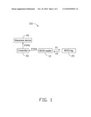
[0007]Referring to FIG. 1, an exemplary embodiment of an intelligent control system 100 includes a radio-frequency identification (RFID) reader 10, an RFID tag 20, a controller 30, and an electronic device 40. The RFID reader 10 is connected to the controller 30. The controller 30 is connected to the electronic device 40. In one exemplary embodiment, the electronic device 40 is a security monitor in a monitored area. The RFID tag 20 is carried by security guards working at the monitored area.
[0008]The RFID reader 10 continuously outputs a radio signal F1. When the RFID tag 20 is in a detectable range of the RFID reader 10, which means the security guard is present, the RFID tag 20 receives the radio signal F1 from the RFID reader 10 and output a radio response signal F2. The RFID reader 10 receives the radio response signal F2 and outputs a first sensed signal F3 to the controller 30. The controller 30 may be a computer or a control chip. The controller 30 receives the first detecting signal F3 and outputs a first control signal F5 to power off the electronic device 40.
[0009]When the RFID tag 20 is not in the detectable range of the RFID reader 10, which means the security guard is not present, the RFID tag 20 cannot receive the radio signal F1 from the RFID reader 10, and does not output the radio response signal F2. The RFID reader 10 then outputs a second detecting signal F4 to the controller 30. The controller 30 receives the second detecting signal F4 and outputs a second control signal F6 to power on the electronic device 40.
[0010]In another exemplary embodiment, the electronic device 40 may be a household appliance, such as an air condition. The RFID tag 20 may be carried by family members. When a RFID tag 20 is in the detectable range of RFID reader 10, the controller 30 controls the household appliance to work. When the RFID tag 20 is not in the detectable range of RFID reader 10, the controller 30 controls the household appliance to stop working.
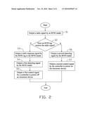
[0011]Referring to FIG. 2, an intelligent control method for the electronic device 40 includes the following steps.
[0012]In step S1, the RFID reader 10 outputs a radio signal F1.
[0013]In step S2, a determination is made on whether the RFID tag 20 receives the radio signal F1 or not. If the RFID tag 20 receives the radio signal F1, the flow goes to step S3. If the RFID tag 20 does not receive the radio signal F1, the flow goes to step S6.
[0014]In step S3, the RFID tag 20 outputs a radio response signal F2 to the RFID reader 10.
[0015]In step S4, the RFID reader 10 outputs a first detecting signal F3 to the controller 30.
[0016]In step S5, the controller 30 outputs a first control signal F5 to power off the electronic device 40.
[0017]In step S6, the RFID reader 10 outputs a second detecting signal F4 to the controller 30.
[0018]In step S7, the controller 30 outputs a second control signal F6 to power on the electronic device 40.
[0019]It is to be understood, however, that even though numerous characteristics and advantages of the present disclosure have been set forth in the foregoing description, together with details of the structure and function of the disclosure, the disclosure is illustrative only, and changes may be made in details, especially in matters of shape, size, and arrangement of parts within the principles of the disclosure to the full extent indicated by the broad general meaning of the terms in which the appended claims are expressed.
Claims:
1. An intelligent control system, comprising:a radio-frequency
identification (RFID) reader to output a radio signal;an RFID tag to
output a radio response signal in response to receiving the radio signal;
wherein the RFID reader is further to output a first detecting signal in
response to receiving the radio response signal, or output a second
detecting signal in response to not receiving the radio response signal;a
controller connected to the RFID reader, to output a first control signal
or a second control signal in response to receiving the first detecting
signal or the second detecting signal from the RFID reader; andan
electronic device connected to the controller, to be powered on or
powered off in response to receiving the first control signal or the
second control signal from the controller.
2. The intelligent control system of claim 1, wherein the controller is a computer or a control chip.
3. The intelligent control system of claim 1, wherein the electronic device is a security monitor.
4. The intelligent control system of claim 1, wherein the electronic device is a household appliance.
5. An intelligent control method for an electronic device, comprising:outputting a radio signal via a radio-frequency identification (RFID) reader;outputting a radio response signal by a RFID tag in response to receiving the radio signal;outputting a first detecting signal by the RFID reader in response to receiving the radio response signal; andoutputting a first control signal by a controller to power off the electronic device in response to receiving the first detecting signal.
6. The method of claim 5, further comprising:outputting a second detecting signal by the RFID reader in response to not receiving the radio response signal; andoutputting a second control signal by the controller to power on the electronic device in response to receiving the second detecting signal.
7. The method of claim 5, wherein the controller is a computer or a control chip.
8. The method of claim 5, wherein the electronic device is a security monitor.
9. The method of claim 5, wherein the electronic device is a household appliance.
Description:
BACKGROUND
[0001]1. Technical Field
[0002]The present disclosure relates to intelligent control systems and methods, and particularly to an intelligent control system and a method for an electronic device.
[0003]2. Description of Related Art
[0004]An electronic device such as a security monitor in a monitored area is almost always powered on. However, in fact, the security monitor is unnecessary to work when a security guard is present. Therefore, power is sometime unnecessarily wasted.
BRIEF DESCRIPTION OF THE DRAWINGS
[0005]FIG. 1 is a block diagram of an exemplary embodiment of an intelligent control system for an electronic device.
[0006]FIG. 2 is a flowchart diagram of an exemplary embodiment of an intelligent control method for an electronic device.
DETAILED DESCRIPTION
[0007]Referring to FIG. 1, an exemplary embodiment of an intelligent control system 100 includes a radio-frequency identification (RFID) reader 10, an RFID tag 20, a controller 30, and an electronic device 40. The RFID reader 10 is connected to the controller 30. The controller 30 is connected to the electronic device 40. In one exemplary embodiment, the electronic device 40 is a security monitor in a monitored area. The RFID tag 20 is carried by security guards working at the monitored area.
[0008]The RFID reader 10 continuously outputs a radio signal F1. When the RFID tag 20 is in a detectable range of the RFID reader 10, which means the security guard is present, the RFID tag 20 receives the radio signal F1 from the RFID reader 10 and output a radio response signal F2. The RFID reader 10 receives the radio response signal F2 and outputs a first sensed signal F3 to the controller 30. The controller 30 may be a computer or a control chip. The controller 30 receives the first detecting signal F3 and outputs a first control signal F5 to power off the electronic device 40.
[0009]When the RFID tag 20 is not in the detectable range of the RFID reader 10, which means the security guard is not present, the RFID tag 20 cannot receive the radio signal F1 from the RFID reader 10, and does not output the radio response signal F2. The RFID reader 10 then outputs a second detecting signal F4 to the controller 30. The controller 30 receives the second detecting signal F4 and outputs a second control signal F6 to power on the electronic device 40.
[0010]In another exemplary embodiment, the electronic device 40 may be a household appliance, such as an air condition. The RFID tag 20 may be carried by family members. When a RFID tag 20 is in the detectable range of RFID reader 10, the controller 30 controls the household appliance to work. When the RFID tag 20 is not in the detectable range of RFID reader 10, the controller 30 controls the household appliance to stop working.
[0011]Referring to FIG. 2, an intelligent control method for the electronic device 40 includes the following steps.
[0012]In step S1, the RFID reader 10 outputs a radio signal F1.
[0013]In step S2, a determination is made on whether the RFID tag 20 receives the radio signal F1 or not. If the RFID tag 20 receives the radio signal F1, the flow goes to step S3. If the RFID tag 20 does not receive the radio signal F1, the flow goes to step S6.
[0014]In step S3, the RFID tag 20 outputs a radio response signal F2 to the RFID reader 10.
[0015]In step S4, the RFID reader 10 outputs a first detecting signal F3 to the controller 30.
[0016]In step S5, the controller 30 outputs a first control signal F5 to power off the electronic device 40.
[0017]In step S6, the RFID reader 10 outputs a second detecting signal F4 to the controller 30.
[0018]In step S7, the controller 30 outputs a second control signal F6 to power on the electronic device 40.
[0019]It is to be understood, however, that even though numerous characteristics and advantages of the present disclosure have been set forth in the foregoing description, together with details of the structure and function of the disclosure, the disclosure is illustrative only, and changes may be made in details, especially in matters of shape, size, and arrangement of parts within the principles of the disclosure to the full extent indicated by the broad general meaning of the terms in which the appended claims are expressed.
User Contributions:
Comment about this patent or add new information about this topic:
Images included with this patent application:
 |  |
 |
| Similar patent applications: | |
| Date | Title |
|---|---|
| 2009-03-19 | Intelligent tire systems and methods |
| 2011-05-12 | Lamp color matching and control systems and methods |
| 2011-07-14 | Integrated condition or actuation monitoring and control component for switches, circuit breakers, panel boards, and other items for electrical control and circuit protection |
| 2010-06-03 | Remote control system and method |
| 2011-06-30 | Surface mounted technology monitoring system and method |
| New patent applications in this class: | |
| Date | Title |
|---|---|
| 2016-07-14 | Sensor hierarchy |
| 2015-11-05 | Systems and methods for automated fish culling |
| 2015-04-23 | Handheld electronic device and operation method of the same |
| 2015-01-22 | Method for determining a parameter set of a perishable product and control system for implementing the method |
| 2014-09-18 | System and method for monitoring water levels |
| New patent applications from these inventors: | |
| Date | Title |
|---|---|
| 2012-12-20 | Electrically conductive foam |
| 2012-09-20 | Container data center |
| 2012-06-14 | Electronic device and power management method thereof |
| 2011-03-17 | Fan module for dissipating heat |
| 2011-03-03 | Fan having two impellers |
| Top Inventors for class "Communications: electrical" | |
| Rank | Inventor's name |
|---|---|
| 1 | Lowell L. Wood, Jr. |
| 2 | Roderick A. Hyde |
| 3 | Juan Manuel Cruz-Hernandez |
| 4 | John R. Tuttle |
| 5 | Jordin T. Kare |