Patent application title: HOLDER FOR ATTACHING A HEADREST TO THE BACK OF A SEAT
Inventors:
Andre Holtzinger (Vescheim, FR)
Jean-Francois Host (Sarrebourg, FR)
Assignees:
Steelcase S.A.
IPC8 Class: AA47C738FI
USPC Class:
297397
Class name: Chairs and seats headrest portable, with seat attacher
Publication date: 2010-11-18
Patent application number: 20100289316
Inventors list |
Agents list |
Assignees list |
List by place |
Classification tree browser |
Top 100 Inventors |
Top 100 Agents |
Top 100 Assignees |
Usenet FAQ Index |
Documents |
Other FAQs |
Patent application title: HOLDER FOR ATTACHING A HEADREST TO THE BACK OF A SEAT
Inventors:
Andre Holtzinger
Jean-Francois Host
Agents:
PRICE HENEVELD COOPER DEWITT & LITTON, LLP
Assignees:
Origin: GRAND RAPIDS, MI US
IPC8 Class: AA47C738FI
USPC Class:
Publication date: 11/18/2010
Patent application number: 20100289316
Abstract:
The invention relates to a seat that comprises: a base; a sitting portion
and a back support mounted on the base; a back including a shell and a
padding attached to the shell; at least one attachment point provided
with attachment means for attaching the back holder to the back; a
headrest; and a headrest holder. The seat further includes: a bearing
profile section adapted for attachment to the top of the shell of the
back; and an arm with a planar aspect extending between the padding and
the shell of the back, wherein said arm extends down to the attachment
point(s) and is held rigidly by the attachment means of the back to the
back holder.Claims:
1-8. (canceled)
9. A chair, comprising:a base;a back holder mounted to the base;a seat portion;a back including a shell and padding;at least one attachment point including connecting structure adapted to attach the back to the back holder;a headrest; anda headrest holder having a bearing profile section adapted to hook to a top of the shell of the back, and an arm having at least a portion thereof extending between the padding and the shell of the back, wherein the arm extends to the one attachment point, and wherein the arm is held rigidly, at least in part, by the connecting structure.
10. The chair of claim 9, wherein:the shell includes a recess defining a shape;the bearing profile section is in the form of a hook;the arm includes at least one positioning stud having a shape corresponding to the shape of the recess in the shell, the one positioning stud fitting into the recess in the shell of the back.
11. The chair of claim 10, wherein:the connecting structure comprises a threaded fastener.
12. The chair of claim 9, wherein:the shell includes a plurality of recesses that are located at a same level;the arm includes a plurality of positioning studs that are horizontally spaced apart from one another, and wherein the studs engage the recesses in the shell.
13. The chair of claim 12, wherein:the arm includes a pair of vertically extending portions having generally planar opposite side surface portions, and dogleg lower sections extending outwardly away from one another, and wherein each dogleg lower section includes at least one stud at an outer end thereof
14. The chair of claim 10, wherein:the one stud comprises a hollow protrusion having a bottom portion with an aperture through the bottom portion, and including:a threaded fastener extending through the aperture and interconnecting the holder, the shell, and the back holder.
15. The chair of claim 9, wherein:the holder for the headrest includes an upper portion having a curved slide rail; andthe headrest is attached to the upper portion.
16. The chair of claim 15, wherein:the upper portion of the holder for the headrest includes a pair of parallel curved slide rails defining upper ends, the upper portion further including a cross member connected to the curved slide rails in the area of the upper ends.
17. The chair of claim 9, wherein:the holder for the headrest comprises nylon PA6 polymer filled with fiberglass in a ratio in the range of 25% to 45%.
Description:
BACKGROUND OF THE INVENTION
[0001]1. Field of the Invention
[0002]This invention deals with a seat and more particularly with a mechanism for attaching a headrest to the back of a seat. It concerns in particular, but not exclusively, office chairs. In order to ensure the users' comfort, whatever their body type, the headrest must be adjustable for height.
[0003](2) Description of the Related Art
[0004]In a number of currently used solutions, the headrest is attached on the holder which is mobile with regard to the back, with the height adjustment being made therefore at the level of the back of the seat. In this scenario, the mechanisms for displacing one element with regard to the other are located on the back. In order to ensure this function, the seat back cannot then be comprised simply of a shell covered with padded upholstery; it must integrate the sometimes sophisticated mechanisms for controlling the displacement of the headrest.
[0005]Even in the case of an adjustment at the level of the headrest, the attachment to the back of a corresponding holder, whose manipulation generates mechanical stress, generally gives rise to the designing of a back which is dimensioned and designed to ensure a stable and secure attachment. The structure is conceived on this basis, and in order not to compromise the comfort of the seat, the attachment is generally made behind the shell, on the side opposite the padded side on which the back of the user rests, or between the two shells.
SUMMARY OF THE INVENTION
[0006]The present invention takes an approach that is the opposite of these solutions, by proposing a headrest attached in a simple and direct manner between the shell forming the back and the padding which covers said shell.
[0007]The seat of the invention, thus allowing the attachment of a headrest to a back, comprises principally: [0008]a base; [0009]a sitting portion and a back support mounted on the base; [0010]a back including a shell and padding attached to the shell; [0011]at least one attachment point provided with means for attaching the back to the back holder; [0012]a headrest; and [0013]a headrest holder,which includes: [0014]a bearing profile section adapted for attachment to the top of the shell of the back; and [0015]an arm of planar aspect extending between the padding and the shell of the back, said arm extending to the point(s) of attachment and being held rigidly by the means of attachment of the back to the back holder.
[0016]Advantageously, said means of attachment provided for within the scope of the invention thus ensures solid attachment of both the back to the back holder and of the headrest holder to the back holder.
[0017]In fact, more precisely, the bearing profile section is in the form of a hook and the arm features at least one positioning stud fitting in a recess of corresponding shape in the shell of the back, where it is attached by the above-cited attachment means.
[0018]The upper linking by the profile section produces, in reality, a simple support at the top of the shell of the back, without additional attachment means, and is completed by an arm allowing a positioning in the width of the back. To simplify, it can be said that the vertical positioning is ensured by the bearing profile section in hook form, whereas the horizontal positioning is made by the positioning stud(s).
[0019]Preferably, the arm actually features two positioning studs offset laterally toward the exterior and cooperating with two recesses located at the same level and centered in the width of the shell.
[0020]The use of the two studs, with their extensions offset laterally towards the exterior, allows the positioning operations to be appreciably facilitated and improves the centering of the headrest.
[0021]According to one possible configuration, the arm features two parallel planar branches of vertical aspect, whose lower ends feature divergent dogleg sections ending in the positioning studs.
[0022]Each stud is designed hollow, with a bottom featuring a centered orifice allowing the attachment of the headrest holder to the shell of the back and to the holder of the back, by means of a bolt, for example.
[0023]The appreciably flat nature of the arm, its slim structure (as will be seen further on) and the fact that the studs are embedded in the recesses of the shell allows the padding of the shell of the back to be ensured under proper conditions, without compromising the comfort of the seat.
[0024]According to one possibility, the headrest is attached to an upper portion of the holder which consists of at least one girder of curved aspect acting as a slide rail for the headrest.
[0025]Preferably, there are two parallel girders connected, in the area of their free end, by a cross member.
[0026]These girders serve as guide rails for the displacement of curvilinear aspect of the headrest, in the vertical direction.
[0027]According to one possibility which takes into account the mechanical stresses necessary for this type of part, the headrest holder is produced in a commercialized material under the protected name of nylon PA6, filled with fiberglass at the ratio of 25%-45%.
BRIEF DESCRIPTION OF THE DRAWINGS
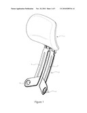
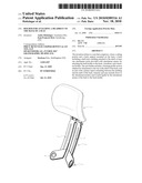
[0028]FIG. 1 is a perspective view of a headrest mounted on a holder in accordance with the attachment mechanism of the invention;
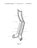
[0029]FIG. 2 is a perspective view of the headrest holder of FIG. 1;
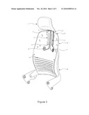
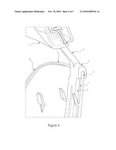
[0030]FIG. 3 is a perspective view of the headrest holder/headrest unit mounted on the shell of the seatback.
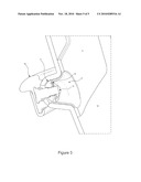
[0031]FIG. 4 is a partial cross section detailing the hooking at the upper part of the shell; and
[0032]FIG. 5 is a partial cross section of the attachment mechanism at the level of the bottom studs.
DETAILED DESCRIPTION OF PREFERRED EMBODIMENT
[0033]Referring to FIG. 1, the headrest (1) is mounted on the upper portion of a headrest holder (2) comprising an arm with two branches (3, 4) of parallel aspect whose lower end is dog-legged and ends in hollow studs (5, 6).
[0034]The holder (2) also appears in FIG. 2, with an upper portion (7) comprised by two parallel curved girders connected, in the area of their free upper end, by a cross member (10). This figure shows clearly that the holder (2) is comprised of an upper portion (7) and a second portion constituted by an arm (11), which are separated by a bearing profile section (12) in the shape of a hook.
[0035]This profile section (12) allows the headrest holder (2) to be hooked on the upper edge (13) of the shell (14) of a seat back, such as is shown in FIG. 3. This shell (14), which is not the subject of the invention, features, at the level of the lumbar region, a series of slits (15) allowing its flexibility to be improved, and it is attached at its bottom portion to a back holder (16) comprising additional means of attachment to the rear of the shell (14), in its middle portion.
[0036]FIG. 4 shows an enlarged detail of the attachment of the headrest holder (2) at the level of the upper edge (13) of the shell (14), by means of the profile section (12). The studs (5) and (6) fit then into the corresponding recesses made in the shell (14) of the back, of which one example (17) is shown in detail in FIG. 5. The bottom (18) of the hollow studs is provided with an orifice allowing the passage of a screw (19) of a bolt, whose head is embedded in the horizontal portion of the back holder (16) running along the back of the shell (14). This screw (19) acts on the one hand to fasten said flexible back holder (16) to the shell (14) of the back, and acts on the other hand to solidly attach the headrest holder (2) of the back (1) to said shell (14). The entire unit is then covered with a padded upholstery. In this respect, as it appears in FIG. 5, the slight thickness of the holder (2) does not constitute in any case an inconvenience for the final user, because this part (2) is covered over by a padded covering of thickness sufficient to ensure comfort.
[0037]The attachment of the holder (2) to the shell (14) is simple, since it consists in a first stage of hooking the profile section (12) on the upper edge (13) of the shell (14), then of centering it in the width of said shell (14) with the aid of the hollow studs (5) and (6), by their fitting into the corresponding recesses. The final attachment is made by means of the bolt featuring the screw (19).
[0038]The example described here-above, illustrated by FIGS. 1 to 5, is in no way exhaustive of the invention. The invention also covers variations such as attachment means equivalent to the bolt, or forms resulting in an equivalent outcome for the branches (3) and (4) or the girders (8) and (9). Preferably, the part (2) is made of nylon PA6 filled with fiberglass. The load should be in the range of 30% to 40%.
User Contributions:
comments("1"); ?> comment_form("1"); ?>Inventors list |
Agents list |
Assignees list |
List by place |
Classification tree browser |
Top 100 Inventors |
Top 100 Agents |
Top 100 Assignees |
Usenet FAQ Index |
Documents |
Other FAQs |
User Contributions:
Comment about this patent or add new information about this topic:
Images included with this patent application:
 |  |
 |  |
 |  |
| Similar patent applications: | |
| Date | Title |
|---|---|
| 2012-09-20 | Structure and method for pivotably supporting an armrest on a seat |
| 2010-12-02 | Seat having a saddle shape to fit a user ergonomically |
| 2011-08-18 | Base body of a headrest of a vehicle seat |
| 2012-11-08 | Headrest media system for a seat back of a vehicle |
| 2012-06-28 | Accessory for aiding those working on their motor skills |
| New patent applications in this class: | |
| Date | Title |
|---|---|
| 2016-09-01 | Headrest safety mechanism and method of use |
| 2016-05-12 | Seat headrest |
| 2016-04-28 | World pillow |
| 2016-04-28 | Travel headrest device with flexible tethers, detachable multi-axis joints and permanent swivel mounting option |
| 2016-04-14 | Compact body support apparatus |
| Top Inventors for class "Chairs and seats" | |
| Rank | Inventor's name |
|---|---|
| 1 | Johnathan Andrew Line |
| 2 | Larry P. Lapointe |
| 3 | Yukifumi Yamada |
| 4 | John W. Jaranson |
| 5 | Erwin Haller |