Patent application title: OIL PAN/AXLE SUPPORT
Inventors:
Brian M. Huenink (Hudson, IA, US)
IPC8 Class: AF02B7700FI
USPC Class:
123195 C
Class name: Internal-combustion engines frame construction all covers
Publication date: 2010-11-18
Patent application number: 20100288223
an oil pan/axle support. There is a need for an
oil pan/axle support which is a structural member and which places the
front axle support in front of the engine. Such an oil pan/axle support
includes a rigid structural housing capable of forming a portion of a
frame of a vehicle. The housing has an aft portion and a forward portion.
The aft portion forms an engine oil reservoir surrounded by a rim. The
rim has an upwardly facing sealing surface for engagement with a block of
an engine. The forward portion extends forward from the aft portion and
forms a pair of fore-and-aft spaced apart pivot bores for receiving a
front axle pivot pin so that the front axle is spaced forward with
respect to a front portion of the engine.Claims:
1. An oil pan/axle support comprising:a rigid structural housing capable
of forming a portion of a frame of a vehicle, the housing having an aft
portion and a forward portion;the aft portion forming an engine oil
reservoir surrounded by a rim, the rim having an upwardly facing sealing
surface for engagement with a block of an engine; andthe forward portion
extending forward from the aft portion and forming a pair of fore-and-aft
spaced apart pivot bores for receiving a front axle pivot pin so that the
front axle is spaced forward with respect to a front portion of the
engine, and the forward portion having an upper edge positioned higher
than the rim of the aft portion.
2. The oil pan/axle support of claim 1, wherein:radiator mounting bosses are formed on upper side surfaces of the forward oil pan portion, said bosses being forward and above the rim of the aft portion.
3. The oil pan/axle support of claim 1, wherein:loader mounting flanges are formed on the sides of the aft portion.
4. The oil pan/axle support of claim 3, wherein:the loader mounting flanges are formed on a rear portion of the aft portion.
5. The oil pan/axle support of claim 1, wherein:a first pair of loader mounting flanges are formed on a left side of the aft portion, and a second pair of loader mounting flanges are formed on a right side of the aft portion.
6. The oil pan/axle support of claim 1, wherein:the front axle pivot pin has an axis which is above a floor of the engine oil reservoir.
7. An oil pan/axle support comprising:a rigid structural housing capable of forming a portion of a frame of a vehicle, the housing having an aft portion and a forward portion;the aft portion forming an engine oil reservoir having a floor surrounded by a rim, the rim having an upwardly facing sealing surface for engagement with a block of an engine; andthe forward portion extending forward from the aft portion and forming a pair of fore-and-aft spaced apart pivot bores for receiving a front axle pivot pin, the pivot bores defining an axis which is above the floor of the engine oil reservoir.Description:
FIELD OF THE INVENTION
[0001]The present invention relates to an oil pan/axle support for a tractor.
BACKGROUND OF THE INVENTION
[0002]Upcoming emission regulations will require the use of additional engine accessories and components. It would be desirable to place such components above an engine, but this cannot be done if there is insufficient space above the engine. For example, there is insufficient space above the engine in a production John Deere 8000 Series tractors. This is because the tractor has an oil pan which serves as a structural member of the tractor frame, and because this structural oil pan supports an axle which is mounted below a front portion of the engine. This raises the position of the engine. It would be desirable to have a robust structural oil pan/axle assembly which permits the engine to be at a lower position, so as to maintain engine to transmission drop distances and maintain a space above the engine for additional components. In addition, to maintain or improve turning radius, attachments between the oil pan and the sides of the engine block should be avoided. Bolted joints between the oil pan and axle support should be avoided to reduce cost and complexity and to increase strength.
SUMMARY OF THE INVENTION
[0003]Accordingly, an object of this invention is to provide an oil pan/axle support unit which serves as a structural member of the tractor frame.
[0004]A further object of the invention is to provide such a an oil pan/axle support unit which supports an axle which is mounted in front of a front portion of the engine.
[0005]These and other objects are achieved by the present invention, wherein an oil pan/axle support includes a rigid structural housing capable of forming a portion of a frame of a vehicle. The housing has an aft portion and a forward portion. The aft portion forms an engine oil reservoir surrounded by a rim. The rim has an upwardly facing sealing surface for engagement with a block of an engine. The forward portion extends forward from the aft portion and forms a pair of fore-and-aft spaced apart pivot bores for receiving a front axle pivot pin so that the front axle is spaced forward with respect to a front portion of the engine.
BRIEF DESCRIPTION OF THE DRAWINGS
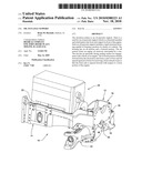
[0006]FIG. 1 is a side view of an oil pan embodying the invention assembled to an engine and a front axle;
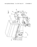
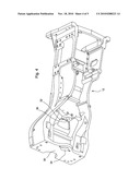
[0007]FIG. 2 is a perspective view of the oil pan of FIG. 1;
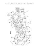
[0008]FIG. 3 is a perspective top view of the oil pan of FIG. 1 without the engine or the front axle;
[0009]FIG. 4 is a perspective bottom view of the oil pan of FIG. 1 without the engine or the front axle; and
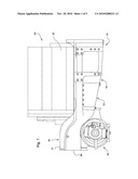
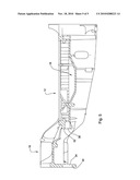
[0010]FIG. 5 is a sectional view along lines 5-5 of FIG. 3.
DESCRIPTION OF THE PREFERRED EMBODIMENT
[0011]Referring to FIGS. 1-5, an oil pan 10 is formed by a rigid structural housing 12, such as a casting, which is capable of forming a portion of a frame of a vehicle (not shown). The housing 12 includes an aft portion 14 and a forward portion 16.
[0012]The aft portion 14 forms an engine oil reservoir 18 with a floor 17 surrounded by a rim 19. Rim 19 forms an upwardly facing sealing surface 20 for engagement with a bottom surface of a block 22 of an engine 24. The block 22 of engine 24 is mounted to the sealing surface 20 so that the front of the engine block 22 is rearward of the forward portion 16 of the oil pan 10, as best seen in FIG. 1.
[0013]The forward portion 16 extends forward and above the aft portion 14 and forms a front wall 30 and a rear wall 32. A pair of fore-and-aft spaced apart pivot bores 34 and 36 extend through walls 30 and 32, respectively. Bores 34 and 36 are adapted to receive a front axle pivot pin 40, so that the front axle 42 is spaced forward with respect to a front portion of the engine 24. The forward portion 16 has an upper edge 17 which is positioned higher than the sealing surface 20 of the aft portion 14. As best seen in FIG. 5, the front axle pivot bore 30 has an axis A which is above the floor 17 of the engine oil reservoir.
[0014]Radiator mounting bosses 44, 46, 48 and 50 are formed on upper side surfaces 52 and 54 of the forward oil pan portion 16. The bosses are forward and above the sealing surface 20 of the aft portion 14. A first pair of loader mounting flanges 60, 62, are formed on a left side of the aft portion 14, and a second pair of loader mounting flanges 64, 66 are formed on a right side of the aft portion 14.
[0015]This oil pan/axle support assembly requires no bolted joint between an oil pan which is separate from an axle support. This requires less material, reduces the amount of machining and reduces the number of parts. Instead, there is a seamless flow of casted material from the oil pan to the front axle support. The front end of this oil pan/axle support assembly is in front of the axle where it can be connected to a front hitch casting (not shown) or a vehicle frame front support (not shown). Thus, the joint at the front end of this oil pan/axle support assembly will be required to support only front hitch and weight loads only. The structure is very resistant to chassis torsion load. Using this structural oil pan improves turning radius and lowers the overall chassis weight needed for higher horsepower levels.
[0016]While the present invention has been described in conjunction with a specific embodiment, it is understood that many alternatives, modifications and variations will be apparent to those skilled in the art in light of the foregoing description. Accordingly, this invention is intended to embrace all such alternatives, modifications and variations which fall within the spirit and scope of the appended claims.
Claims:
1. An oil pan/axle support comprising:a rigid structural housing capable
of forming a portion of a frame of a vehicle, the housing having an aft
portion and a forward portion;the aft portion forming an engine oil
reservoir surrounded by a rim, the rim having an upwardly facing sealing
surface for engagement with a block of an engine; andthe forward portion
extending forward from the aft portion and forming a pair of fore-and-aft
spaced apart pivot bores for receiving a front axle pivot pin so that the
front axle is spaced forward with respect to a front portion of the
engine, and the forward portion having an upper edge positioned higher
than the rim of the aft portion.
2. The oil pan/axle support of claim 1, wherein:radiator mounting bosses are formed on upper side surfaces of the forward oil pan portion, said bosses being forward and above the rim of the aft portion.
3. The oil pan/axle support of claim 1, wherein:loader mounting flanges are formed on the sides of the aft portion.
4. The oil pan/axle support of claim 3, wherein:the loader mounting flanges are formed on a rear portion of the aft portion.
5. The oil pan/axle support of claim 1, wherein:a first pair of loader mounting flanges are formed on a left side of the aft portion, and a second pair of loader mounting flanges are formed on a right side of the aft portion.
6. The oil pan/axle support of claim 1, wherein:the front axle pivot pin has an axis which is above a floor of the engine oil reservoir.
7. An oil pan/axle support comprising:a rigid structural housing capable of forming a portion of a frame of a vehicle, the housing having an aft portion and a forward portion;the aft portion forming an engine oil reservoir having a floor surrounded by a rim, the rim having an upwardly facing sealing surface for engagement with a block of an engine; andthe forward portion extending forward from the aft portion and forming a pair of fore-and-aft spaced apart pivot bores for receiving a front axle pivot pin, the pivot bores defining an axis which is above the floor of the engine oil reservoir.
Description:
FIELD OF THE INVENTION
[0001]The present invention relates to an oil pan/axle support for a tractor.
BACKGROUND OF THE INVENTION
[0002]Upcoming emission regulations will require the use of additional engine accessories and components. It would be desirable to place such components above an engine, but this cannot be done if there is insufficient space above the engine. For example, there is insufficient space above the engine in a production John Deere 8000 Series tractors. This is because the tractor has an oil pan which serves as a structural member of the tractor frame, and because this structural oil pan supports an axle which is mounted below a front portion of the engine. This raises the position of the engine. It would be desirable to have a robust structural oil pan/axle assembly which permits the engine to be at a lower position, so as to maintain engine to transmission drop distances and maintain a space above the engine for additional components. In addition, to maintain or improve turning radius, attachments between the oil pan and the sides of the engine block should be avoided. Bolted joints between the oil pan and axle support should be avoided to reduce cost and complexity and to increase strength.
SUMMARY OF THE INVENTION
[0003]Accordingly, an object of this invention is to provide an oil pan/axle support unit which serves as a structural member of the tractor frame.
[0004]A further object of the invention is to provide such a an oil pan/axle support unit which supports an axle which is mounted in front of a front portion of the engine.
[0005]These and other objects are achieved by the present invention, wherein an oil pan/axle support includes a rigid structural housing capable of forming a portion of a frame of a vehicle. The housing has an aft portion and a forward portion. The aft portion forms an engine oil reservoir surrounded by a rim. The rim has an upwardly facing sealing surface for engagement with a block of an engine. The forward portion extends forward from the aft portion and forms a pair of fore-and-aft spaced apart pivot bores for receiving a front axle pivot pin so that the front axle is spaced forward with respect to a front portion of the engine.
BRIEF DESCRIPTION OF THE DRAWINGS
[0006]FIG. 1 is a side view of an oil pan embodying the invention assembled to an engine and a front axle;
[0007]FIG. 2 is a perspective view of the oil pan of FIG. 1;
[0008]FIG. 3 is a perspective top view of the oil pan of FIG. 1 without the engine or the front axle;
[0009]FIG. 4 is a perspective bottom view of the oil pan of FIG. 1 without the engine or the front axle; and
[0010]FIG. 5 is a sectional view along lines 5-5 of FIG. 3.
DESCRIPTION OF THE PREFERRED EMBODIMENT
[0011]Referring to FIGS. 1-5, an oil pan 10 is formed by a rigid structural housing 12, such as a casting, which is capable of forming a portion of a frame of a vehicle (not shown). The housing 12 includes an aft portion 14 and a forward portion 16.
[0012]The aft portion 14 forms an engine oil reservoir 18 with a floor 17 surrounded by a rim 19. Rim 19 forms an upwardly facing sealing surface 20 for engagement with a bottom surface of a block 22 of an engine 24. The block 22 of engine 24 is mounted to the sealing surface 20 so that the front of the engine block 22 is rearward of the forward portion 16 of the oil pan 10, as best seen in FIG. 1.
[0013]The forward portion 16 extends forward and above the aft portion 14 and forms a front wall 30 and a rear wall 32. A pair of fore-and-aft spaced apart pivot bores 34 and 36 extend through walls 30 and 32, respectively. Bores 34 and 36 are adapted to receive a front axle pivot pin 40, so that the front axle 42 is spaced forward with respect to a front portion of the engine 24. The forward portion 16 has an upper edge 17 which is positioned higher than the sealing surface 20 of the aft portion 14. As best seen in FIG. 5, the front axle pivot bore 30 has an axis A which is above the floor 17 of the engine oil reservoir.
[0014]Radiator mounting bosses 44, 46, 48 and 50 are formed on upper side surfaces 52 and 54 of the forward oil pan portion 16. The bosses are forward and above the sealing surface 20 of the aft portion 14. A first pair of loader mounting flanges 60, 62, are formed on a left side of the aft portion 14, and a second pair of loader mounting flanges 64, 66 are formed on a right side of the aft portion 14.
[0015]This oil pan/axle support assembly requires no bolted joint between an oil pan which is separate from an axle support. This requires less material, reduces the amount of machining and reduces the number of parts. Instead, there is a seamless flow of casted material from the oil pan to the front axle support. The front end of this oil pan/axle support assembly is in front of the axle where it can be connected to a front hitch casting (not shown) or a vehicle frame front support (not shown). Thus, the joint at the front end of this oil pan/axle support assembly will be required to support only front hitch and weight loads only. The structure is very resistant to chassis torsion load. Using this structural oil pan improves turning radius and lowers the overall chassis weight needed for higher horsepower levels.
[0016]While the present invention has been described in conjunction with a specific embodiment, it is understood that many alternatives, modifications and variations will be apparent to those skilled in the art in light of the foregoing description. Accordingly, this invention is intended to embrace all such alternatives, modifications and variations which fall within the spirit and scope of the appended claims.
User Contributions:
Comment about this patent or add new information about this topic:
| People who visited this patent also read: | |
| Patent application number | Title |
|---|---|
| 20180074635 | COMMON PLATFORM USER TOUCH INTERFACE |
| 20180074634 | SENSOR-EQUIPPED DISPLAY DEVICE |
| 20180074633 | DISPLAY PANEL WITH TOUCH DETECTION FUNCTION, DRIVE CIRCUIT, AND ELECTRONIC UNIT |
| 20180074632 | LIGHT EMITTING DIODE SWITCH DEVICE AND ARRAY |
| 20180074631 | INPUT DEVICE |
Images included with this patent application:
 |  |
 |  |
 |  |
| Similar patent applications: | |
| Date | Title |
|---|---|
| 2009-01-29 | Pre-loaded internal fuel manifold support |
| 2012-12-20 | Sensor abnormality detection apparatus and a block heater installation determining apparatus |
| 2008-10-23 | Power plant and fuel supply method therefor |
| 2010-12-02 | Oil pan structure and separator for partitioning oil pan |
| 2011-10-13 | Injectors utilizing lattice support structure |
| New patent applications in this class: | |
| Date | Title |
|---|---|
| 2016-03-31 | Internal combustion engine for vehicle |
| 2015-12-10 | Engine cover for absorbing vibration and assembling method thereof |
| 2015-10-29 | Bearing frame or cylinder head cover |
| 2015-04-09 | Internal combustion engine and structure of chain cover of the same |
| 2015-04-09 | Compression boss for engine front cover |
| Top Inventors for class "Internal-combustion engines" | |
| Rank | Inventor's name |
|---|---|
| 1 | Ross Dykstra Pursifull |
| 2 | Gopichandra Surnilla |
| 3 | Joseph Norman Ulrey |
| 4 | Thomas G. Leone |
| 5 | Chris Paul Glugla |