Patent application title: DIGITAL MULTI RANGE LIQUID LEVEL DETECTOR
Inventors:
Steve Boa (Montreal, CA)
IPC8 Class: AG01F2326FI
USPC Class:
702 55
Class name: Mechanical measurement system fluid measurement (e.g., mass, pressure, viscosity) liquid level or volume determination
Publication date: 2010-11-11
Patent application number: 20100286933
uid level detector to verify and maintain a
predetermined level in a container. The level is measured by a capacitive
sensor located above or in the liquid to be maintained. The capacitive
sensor is composed of a pair of probe connected to a signal converter
chip to obtain a digital data. The digital data is then compared to a
reference value obtain during the initial calibration. The present
invention is composed of two paired components, a capacitive digital
sensor and a fluid control valve that can be installed at different
locations. The sensor determines the liquid level and then transmits the
acquired data to the fluid valve control receiver via wire or radio
frequency (RF). The sensor and valve are programmable in order to
evaluate different possibilities such as water level, water activities
and recurring low level demands. They can also be reprogrammed.Claims:
1. A digital multi range liquid level detector controller to determine and
maintain the level of liquid in a container with or without the need of a
physical contact with liquid comprising:capacitive digital sensor
controller and fluid control valve;a said capacitive digital sensor
controller that is composed of capacitive electrode with a capacitive
converter IC chip to obtain digital data coupled with a logic printed
circuit board for data processing and transmitting.a said fluid control
valve that is composed of a solenoid actuated valve coupled with a logic
printed circuit board for receiving and processing acquired data.
2. The capacitive digital sensor of claim 1 wherein said capacitive electrodes are spaced apart in parallel and oriented planar to the liquid surface.
3. The capacitive electrodes of claim 1 wherein said capacitive converter is used to convert a capacitive signal in order to create a range of detection signals.
4. The capacitive digital sensor of claim 1 wherein said capacitive converter is coupled to a said logic printed circuit board to determine if the collected data is within the created range of detection signal.
5. The capacitive digital sensor of claim 4 wherein said logic printed circuit board transmits data to the receiver if collected signal is not within the predetermined range.
6. The capacitive digital sensor and the fluid control valve logic printed board of claim 1 are programmable in order to process data within the predetermined range and evaluate different possibilities such as water level, water activities and recurring low level demands.
7. The capacitive digital sensor and the fluid control valve logic printed board of claim 1 are reprogrammable.Description:
CROSS-REFERENCE TO RELATED APPLICATIONS
[0001]The present application claims the priority of U.S. provisional patent application No. 61/176,215 filed on May 7, 2009.
BACKGROUND
[0002]1. Field of the Invention
[0003]The present invention relates to the field of detecting devices. More particularly, this invention relates to a digital multi range liquid level detector to verify and maintain a predetermined level of liquid in a container.
[0004]2. Prior Art
[0005]Liquid level detection is important in many applications. For instance, in a swimming pool, water level can vary significantly due to swimmer activities, water leak in accessories such as solar heater and evaporation. These problems can cause damage to the pump and sidewall of the pool. Several inventors have tried to solve these problems by adding mechanical floating valves or floats combined with electric solenoid but all these inventions involve a mechanical floating device.
[0006]For example, U.S. Pat. No. 10,415,526 shows a liquid level controller including a radio frequency transmitter and receiver. The transmitter determines the water level using a floating magnet which closes a magnetic switch in lower and upper position. The movable floating magnet is installed in a perforated hollow cylinder. The floating magnet can get stuck in the hollow cylinder and cause failures.
[0007]U.S. Pat. No. 10,823,184 shows a similar device except that they use an immersed probe. U.S. Pat. No. 10,394,947 shows a capacitive sensor that's use a reference electrode and a capacitive electrode of larger area. While such a system is workable, improvements are desirable.
SUMMARY OF THE INVENTION
[0008]The present invention provides an efficient way to determine and maintain the level of liquid in a container with or without the need of a physical contact with liquid. The level is measured by a capacitive sensor located above or in the liquid to be maintained. The capacitive sensor is composed of a pair of probes connected to a signal converter IC chip to obtain digital data. The digital data is then compared to a reference value obtain during the initial calibration. The present invention is composed of two paired components, a capacitive digital sensor and a fluid control valve that can be installed at different locations. The sensor determines the liquid level and then transmits the acquired data to the valve control receiver via wire or radio frequency (RF) module. The radio frequency module option uses a predetermined unique high security code which eliminates any danger of interference from an outside signal source. The data is processed through a program implemented in the valve and sensor microprocessors.
[0009]The foregoing and other objects, features, and advantages of this invention will become more readily apparent from the following detailed description of a preferred embodiment with reference to the accompanying drawings, wherein the preferred embodiment of the invention is shown and described, by way of examples. As will be realized, the invention is capable of other and different embodiments, and its several details are capable of modifications in various obvious respects, all without departing from the invention. Accordingly, the drawings and descriptions are to be regarded as illustrative in nature, and not as restrictive.
BRIEF DESCRIPTION OF THE PREFERRED EMBODIMENT
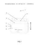
[0010]FIG. 1 See-through orthogonal view of the digital multi range liquid level detector mounted on adjustable height bracket in front position.
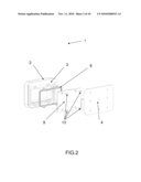
[0011]FIG. 2 See-through exploded view of the digital multi range liquid level detector in backward position.
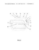
[0012]FIG. 3 See-through exploded view of the interior of the digital multi range liquid level detector in backward position.
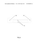
[0013]FIG. 4 See-through bottom view elevation of the capacitive sensor.
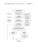
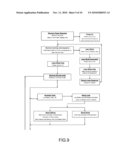
[0014]FIG. 5-6 is a block diagram of the operational features of the transmitter sensor unit.
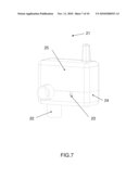
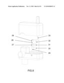
[0015]FIG. 7-8 See-through orthogonal view of the fluid control valve in front position.
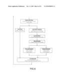
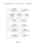
[0016]FIG. 9-10 is a block diagram of the operational features of the fluid valve receiver unit.
DETAILED DESCRIPTION OF THE PREFERRED EMBODIMENT
[0017]FIG. 1 A digital multi range liquid level detector (1) as illustrated is composed of a sensor housing (2) that is permanently assembled to a cover (3) that is mounted in order to permit a vertical adjustment with the sensor bracket (4). The front of the sensor housing (2) is translucent in order to see low level LED (5), high level LED (6) and transmitting LED (7).
[0018]FIG. 2 The sensor housing (2) and the cover (3) contain electronic components and a battery (not shown) in a waterproof removable cover (9) that is sealed with a gasket (8) assembled with screw (10).
[0019]FIG. 3-4-5-6 The sensor housing (2) contains printed circuit board (11) on which is mounted a program connector (12) that permits the communication with microprocessor IC (14). The microprocessor IC (14) is implemented with a program that is represented in the block diagram of the FIG. 5-6. The activation of the button (13) can activate the learning code sequence or start calibration depending of press delay shown in block diagram of the FIG. 5-6. The reed switch (15) is used to save energy when sensor bracket (4) is not assembled with the cover (3). The antenna (16) is used with the transmitter module (not shown) but not installed when the sensor is wire mounted. The sensor printed circuit board (20) is composed of capacitive electrodes (19) that are mounted parallel to the detected liquid. The capacitance converter AD7151 (18) communicates with microprocessor IC (14) via electrical connector (17).
[0020]FIG. 7-8 The fluid control valve (21) as illustrated is composed of solenoid valve (22), a housing (24), a cover (25), a screw (23) and a printed circuit board (26). The printed circuit board (26) is composed of a relay (29) to activate the solenoid valve (22), a beeper (30) for the alarm, a power connector (27), a reset button (28) a port (31) for either sensor cable or antenna (33) for optional radio frequency data transmission via module receiver (not shown).
Claims:
1. A digital multi range liquid level detector controller to determine and
maintain the level of liquid in a container with or without the need of a
physical contact with liquid comprising:capacitive digital sensor
controller and fluid control valve;a said capacitive digital sensor
controller that is composed of capacitive electrode with a capacitive
converter IC chip to obtain digital data coupled with a logic printed
circuit board for data processing and transmitting.a said fluid control
valve that is composed of a solenoid actuated valve coupled with a logic
printed circuit board for receiving and processing acquired data.
2. The capacitive digital sensor of claim 1 wherein said capacitive electrodes are spaced apart in parallel and oriented planar to the liquid surface.
3. The capacitive electrodes of claim 1 wherein said capacitive converter is used to convert a capacitive signal in order to create a range of detection signals.
4. The capacitive digital sensor of claim 1 wherein said capacitive converter is coupled to a said logic printed circuit board to determine if the collected data is within the created range of detection signal.
5. The capacitive digital sensor of claim 4 wherein said logic printed circuit board transmits data to the receiver if collected signal is not within the predetermined range.
6. The capacitive digital sensor and the fluid control valve logic printed board of claim 1 are programmable in order to process data within the predetermined range and evaluate different possibilities such as water level, water activities and recurring low level demands.
7. The capacitive digital sensor and the fluid control valve logic printed board of claim 1 are reprogrammable.
Description:
CROSS-REFERENCE TO RELATED APPLICATIONS
[0001]The present application claims the priority of U.S. provisional patent application No. 61/176,215 filed on May 7, 2009.
BACKGROUND
[0002]1. Field of the Invention
[0003]The present invention relates to the field of detecting devices. More particularly, this invention relates to a digital multi range liquid level detector to verify and maintain a predetermined level of liquid in a container.
[0004]2. Prior Art
[0005]Liquid level detection is important in many applications. For instance, in a swimming pool, water level can vary significantly due to swimmer activities, water leak in accessories such as solar heater and evaporation. These problems can cause damage to the pump and sidewall of the pool. Several inventors have tried to solve these problems by adding mechanical floating valves or floats combined with electric solenoid but all these inventions involve a mechanical floating device.
[0006]For example, U.S. Pat. No. 10,415,526 shows a liquid level controller including a radio frequency transmitter and receiver. The transmitter determines the water level using a floating magnet which closes a magnetic switch in lower and upper position. The movable floating magnet is installed in a perforated hollow cylinder. The floating magnet can get stuck in the hollow cylinder and cause failures.
[0007]U.S. Pat. No. 10,823,184 shows a similar device except that they use an immersed probe. U.S. Pat. No. 10,394,947 shows a capacitive sensor that's use a reference electrode and a capacitive electrode of larger area. While such a system is workable, improvements are desirable.
SUMMARY OF THE INVENTION
[0008]The present invention provides an efficient way to determine and maintain the level of liquid in a container with or without the need of a physical contact with liquid. The level is measured by a capacitive sensor located above or in the liquid to be maintained. The capacitive sensor is composed of a pair of probes connected to a signal converter IC chip to obtain digital data. The digital data is then compared to a reference value obtain during the initial calibration. The present invention is composed of two paired components, a capacitive digital sensor and a fluid control valve that can be installed at different locations. The sensor determines the liquid level and then transmits the acquired data to the valve control receiver via wire or radio frequency (RF) module. The radio frequency module option uses a predetermined unique high security code which eliminates any danger of interference from an outside signal source. The data is processed through a program implemented in the valve and sensor microprocessors.
[0009]The foregoing and other objects, features, and advantages of this invention will become more readily apparent from the following detailed description of a preferred embodiment with reference to the accompanying drawings, wherein the preferred embodiment of the invention is shown and described, by way of examples. As will be realized, the invention is capable of other and different embodiments, and its several details are capable of modifications in various obvious respects, all without departing from the invention. Accordingly, the drawings and descriptions are to be regarded as illustrative in nature, and not as restrictive.
BRIEF DESCRIPTION OF THE PREFERRED EMBODIMENT
[0010]FIG. 1 See-through orthogonal view of the digital multi range liquid level detector mounted on adjustable height bracket in front position.
[0011]FIG. 2 See-through exploded view of the digital multi range liquid level detector in backward position.
[0012]FIG. 3 See-through exploded view of the interior of the digital multi range liquid level detector in backward position.
[0013]FIG. 4 See-through bottom view elevation of the capacitive sensor.
[0014]FIG. 5-6 is a block diagram of the operational features of the transmitter sensor unit.
[0015]FIG. 7-8 See-through orthogonal view of the fluid control valve in front position.
[0016]FIG. 9-10 is a block diagram of the operational features of the fluid valve receiver unit.
DETAILED DESCRIPTION OF THE PREFERRED EMBODIMENT
[0017]FIG. 1 A digital multi range liquid level detector (1) as illustrated is composed of a sensor housing (2) that is permanently assembled to a cover (3) that is mounted in order to permit a vertical adjustment with the sensor bracket (4). The front of the sensor housing (2) is translucent in order to see low level LED (5), high level LED (6) and transmitting LED (7).
[0018]FIG. 2 The sensor housing (2) and the cover (3) contain electronic components and a battery (not shown) in a waterproof removable cover (9) that is sealed with a gasket (8) assembled with screw (10).
[0019]FIG. 3-4-5-6 The sensor housing (2) contains printed circuit board (11) on which is mounted a program connector (12) that permits the communication with microprocessor IC (14). The microprocessor IC (14) is implemented with a program that is represented in the block diagram of the FIG. 5-6. The activation of the button (13) can activate the learning code sequence or start calibration depending of press delay shown in block diagram of the FIG. 5-6. The reed switch (15) is used to save energy when sensor bracket (4) is not assembled with the cover (3). The antenna (16) is used with the transmitter module (not shown) but not installed when the sensor is wire mounted. The sensor printed circuit board (20) is composed of capacitive electrodes (19) that are mounted parallel to the detected liquid. The capacitance converter AD7151 (18) communicates with microprocessor IC (14) via electrical connector (17).
[0020]FIG. 7-8 The fluid control valve (21) as illustrated is composed of solenoid valve (22), a housing (24), a cover (25), a screw (23) and a printed circuit board (26). The printed circuit board (26) is composed of a relay (29) to activate the solenoid valve (22), a beeper (30) for the alarm, a power connector (27), a reset button (28) a port (31) for either sensor cable or antenna (33) for optional radio frequency data transmission via module receiver (not shown).
User Contributions:
Comment about this patent or add new information about this topic:
Images included with this patent application:
 |  |
 |  |
 |  |
 |  |
 |  |
| New patent applications in this class: | |
| Date | Title |
|---|---|
| 2017-08-17 | System and method for identifying a fuel loss |
| 2016-12-29 | Method and apparatus for monitoring, communicating, and analyzing the amount of fluid in a tank |
| 2016-06-16 | Method for determining a filling level of a fluid tank in a motor vehicle |
| 2016-06-09 | Real time detection of aspiration short shots using pressure signal |
| 2016-04-07 | Method and apparatus for monitoring, communicating, and analyzing the amount of fluid in a tank |
| New patent applications from these inventors: | |
| Date | Title |
|---|---|
| 2015-10-08 | Docking station apparatus for a portable device |
| 2012-05-03 | Underwater and landscape lighting system |
| 2011-06-30 | Head-mounted device for settable compound delivery system for inflatable in-ear device |
| Top Inventors for class "Data processing: measuring, calibrating, or testing" | |
| Rank | Inventor's name |
|---|---|
| 1 | Lowell L. Wood, Jr. |
| 2 | Roderick A. Hyde |
| 3 | Shelten Gee Jao Yuen |
| 4 | James Park |
| 5 | Chih-Kuang Chang |