Patent application title: Distributed Ultracapacitor Monitoring System Based on iCAN Protocol
Inventors:
Zhengda Gong (Yangzhou, CN)
Quanshun Liang (Yangzhou, CN)
Li Hua (Shanghai, CN)
IPC8 Class: AB60L300FI
USPC Class:
307 91
Class name: Electrical transmission or interconnection systems vehicle mounted systems
Publication date: 2010-10-28
Patent application number: 20100270859
Inventors list |
Agents list |
Assignees list |
List by place |
Classification tree browser |
Top 100 Inventors |
Top 100 Agents |
Top 100 Assignees |
Usenet FAQ Index |
Documents |
Other FAQs |
Patent application title: Distributed Ultracapacitor Monitoring System Based on iCAN Protocol
Inventors:
Zhengda Gong
Quanshun Liang
Li Hua
Agents:
PROSKAUER ROSE LLP
Assignees:
Origin: BOSTON, MA US
IPC8 Class: AB60L300FI
USPC Class:
Publication date: 10/28/2010
Patent application number: 20100270859
Abstract:
Described are a method and apparatus for an ultracapacitor monitoring
system used on an electric vehicle powered by ultracapacitors. The
ultracapacitor monitoring system includes a plurality of ultracapacitors,
a distributed communication network, a host control device and one or
more child node devices. The plurality of ultracapacitors are coupled to
an electric motor module of the vehicle for providing power. The
distributed communication network is based on the iCAN protocol. The host
control device is coupled to the distributed communication network and
includes a host iCAN processing unit for communicating with the
distributed communication network. Each child node device includes a
child iCAN processing unit for communicating with the host control device
over the distributed communication network. Each of the one or more child
node devices is coupled to a sensor device for one or more of the
plurality of ultracapacitors.Claims:
1. An ultracapacitor monitoring system for an electric vehicle powered by
ultracapacitors, the ultracapacitor monitoring system comprising:a
plurality of ultracapacitors coupled to an electric motor module for
providing power to the vehicle;a distributed communication network medium
including one or more transmission links;a host control device coupled to
the distributed communication network medium and including a host iCAN
processing unit for communicating iCAN control messages with the
distributed communication network medium; andone or more child node
devices, each child node device including a child iCAN processing unit
for communicating iCAN control messages with the host control device over
the distributed communication network medium, each of the one or more
child node devices coupled to a sensor device for one or more of the
plurality of ultracapacitors.
2. The ultracapacitor monitoring system of claim 1 wherein the sensor device comprises a temperature measurement device, a voltage measurement device, a current measurement device, or any combination thereof.
3. The ultracapacitor monitoring system of claim 1 wherein the host control device is coupled to a controller area network (CAN) of the vehicle.
4. The ultracapacitor monitoring system of claim 3 wherein the host control device communicates with the CAN using the SAE J1939 protocol.
5. The ultracapacitor monitoring system of claim 1 wherein the host control device comprises an overall current measuring interface connected to a current sensor for measuring the overall current of the plurality of ultracapacitors.
6. The ultracapacitor monitoring system of claim 1 wherein the host control device comprises an overall voltage measuring interface connected to a voltage sensor for measuring the overall voltage of the plurality of ultracapacitors.
7. The ultracapacitor monitoring system of claim 1 further comprising an LCD diagnostic device connected to the host control device.
8. The ultracapacitor monitoring system of claim 1 further comprising an air blower device connected to the host control device.
9. The ultracapacitor monitoring system of claim 1 wherein the host control device comprises a LPC2368 controller.
10. The ultracapacitor monitoring system of claim 1 wherein each of the child node devices comprise a LPC2368 controller.
11. A method of operating an ultracapacitor monitoring system for an electric vehicle powered by ultracapacitors, the method comprising:connecting a host control device and one or more child node devices to a distributed communication network medium;connecting each of the one or more child node devices to a sensor device for one or more of a plurality of ultracapacitors, the plurality of ultracapacitors coupled to an electric motor module for providing power to the vehicle;transmitting control messages, using the iCAN protocol, from the host control device to each of the child node devices over the distributed communication network medium; andtransmitting sensor messages, using the iCAN protocol, from each of the child node devices to the host control device over the distributed communication network medium.
Description:
RELATED APPLICATIONS
[0001]This application claims the benefit of and priority to Chinese Patent Application Nos. 200910057119.1 and 200910057120.4, each filed on Apr. 24, 2009, the disclosures of which are incorporated herein by reference in their entirety.
FIELD OF THE INVENTION
[0002]The present invention relates generally to a method and an apparatus for a distributed ultracapacitor monitoring system. In particular, it relates to a distributed ultracapacitor monitoring system based on iCAN protocol.
BACKGROUND
[0003]Existing ultracapacitor powered buses or automobiles are driven by electric energy stored in ultracapacitors. The ultracapacitor also supplies power to assisting operating devices. Vehicles powered by ultracapacitors can charge when they are stopped at stations (e.g., bus stations) in a traffic system. When the ultracapacitor needs to charge, it can utilize the existing rectified DC network for trolleybuses as the power source or, after reducing (or lifting) voltage and rectifying, can utilize an AC network as the power source. Because ultracapacitors have high charge acceptance, through rapid charger, the charging process can be finished within tens of seconds while the vehicle or bus stops at the station and loads passengers. Therefore, buses powered by ultracapacitor can be suitable for city public traffic systems that have fixed routes. The system is electric-powered, can have zero-tail-gas-emissions and zero-pollution. It can be used in numerous scenarios including, but not limited to, fixed public traffic routes such as short-distance large passenger-flow routes in downtown areas and/or passenger transport systems for airport, dock, tourist resorts and/or residential districts.
SUMMARY OF THE INVENTION
[0004]Ultracapacitor powered buses can include a distributed ultracapacitor monitoring system in order to provide feedback for controlling and maximizing the efficiency of the operation of the ultracapacitors. Ultracapacitor monitoring systems are a key technology in the operation of vehicles powered by ultracapacitors. To obtain optimum performance of ultracapacitors in one or more working conditions, a high-performance, high-reliability monitoring system is provided. The monitoring system can monitor the status of ultracapacitors in real-time, such as, for example, voltage, charge-discharge current, operating temperature, and/or other status variables. The monitoring system also can forecast the internal impedance and capacitance of ultracapacitors in order to prevent over-charge or over-discharge of the ultracapacitors. By performing one or more of these operations, the reliability and the safety of the vehicles can be improved. Typical ultracapacitor monitoring systems do not achieve these objectives.
[0005]In some aspects, this invention incorporates a real-time deterministic-based networking protocol to advantageously provide a highly intelligent, precisely measured ultracapacitor monitoring system for vehicles.
[0006]One approach to monitoring ultracapacitors on an electric-powered vehicle is to provide a distributed monitoring system. The invention, in one aspect, includes an ultracapacitor monitoring system for an electric vehicle powered by ultracapacitors. The ultracapacitor monitoring system includes a plurality of ultracapacitors, a distributed communication network medium including one or more transmission links, a host control device and one or more child node devices. The plurality of ultracapacitors are coupled to an electric motor module for providing power to the vehicle. The distributed communication network is based on the iCAN protocol. The host control device is coupled to the distributed communication network medium and includes a host iCAN processing unit for communicating iCAN messages with the distributed communication network medium. Each child node device includes a child iCAN processing unit for communicating iCAN messages with the host control device over the distributed communication network medium. Each of the one or more child node devices is coupled to a sensor device for one or more of the plurality of ultracapacitors.
[0007]In another aspect, there is a method of operating an ultracapacitor monitoring system for an electric vehicle powered by ultracapacitors. The method includes connecting a host control device and one or more child node devices to a distributed communication network medium. The method also includes connecting each of the one or more child node devices to a sensor device for one or more of a plurality of ultracapacitors. The plurality of ultracapacitors are coupled to an electric motor module for providing power to the vehicle. The method also includes transmitting control messages, using the iCAN protocol, from the host control device to each of the child node devices over the distributed communication network medium. The method also includes transmitting sensor messages, using the iCAN protocol, from each of the child node devices to the host control device over the distributed communication network medium.
[0008]In other examples, any of the aspects above can include one or more of the following features. In some embodiments, the sensor device can include a temperature measurement device, a voltage measurement device, a current measurement device, or any combination thereof. The host control device can be coupled to a controller area network (CAN) of the vehicle. The host control device can communicate with the CAN using the SAE J1939 protocol. The host control device can include an overall current measuring interface connected to a current sensor for measuring the overall current of the plurality of ultracapacitors. The host control device can include an overall voltage measuring interface connected to a voltage sensor for measuring the overall voltage of the plurality of ultracapacitors. The ultracapacitor monitoring system can further include an LCD diagnostic device connected to the host control device. The ultracapacitor monitoring system can further include an air blower device connected to the host control device. The host control device can include a LPC2368 controller. Each of the child node devices can include a LPC2368 controller.
[0009]Any of the above implementations can realize one or more of the following advantages. By using an iCAN protocol, communications in a distributed ultracapacitor monitoring system can be made highly intelligent, precisely measured, and/or able-to-detect incipient failure of ultracapacitor module. The system can be highly stable, and be able to react in real-time, thereby improving the expandability and portability of the system.
[0010]Other aspects, examples, and advantages of the present invention will become apparent from the following detailed description, taken in conjunction with the accompanying drawings, illustrating the principles of the invention by way of example only.
BRIEF DESCRIPTION OF THE DRAWINGS
[0011]The foregoing and other features and advantages of the present invention, as well as the invention itself, will be more fully understood from the following description of various embodiments, when read together with the accompanying drawings.
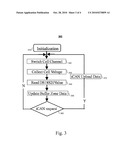
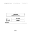
[0012]FIG. 1 illustrates a block diagram of the iCAN protocol's communication layer structure.
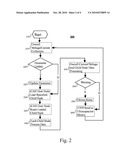
[0013]FIG. 2 illustrates a software flow diagram of a monitoring system host node, according to an illustrative embodiment of the invention.
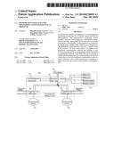
[0014]FIG. 3 illustrates a software flow diagram of a child node, according to an illustrative embodiment of the invention.
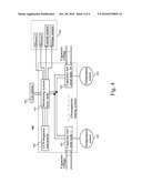
[0015]FIG. 4 illustrates a block diagram of a distributed ultracapacitor monitoring system, according to an illustrative embodiment of the invention.
DETAILED DESCRIPTION
[0016]The iCAN protocol, an open protocol developed by Zhiyuan Electrics Co., Ltd. in Guangzhou, China, is an application layer protocol based on controller area network (CAN)-bus connections, the entire contents of which are incorporated herein by reference. The iCAN (also referred to as "Industrial CAN") protocol can advantageously provide for a simple, easy-to-use and reliable communication protocol. In some embodiments, the iCAN protocol can provide a simple, reliable and stable application layer protocol to small and/or medium CAN-bus networks. The iCAN protocol includes aspects of DeviceNet protocol and CANopen protocol to allow for giving first priority to the reliability and the real-time response of the communication data. Data communication can be conducted in a relatively simple way so that the hardware cost is effectively reduced.
[0017]The iCAN protocol can provide for an easy-to-build CAN-bus network for industrial control area. The iCAN protocol can also offer a low-cost solution to industrial field devices (e.g., sensors and/or instruments) and supervisory equipment (e.g., industrial computers and/or PLCs). The iCAN protocol can explicitly define the distribution and application of ID and data in CAN messages. The iCAN protocol can also define the I/O resources and access rules of the devices.
[0018]FIG. 1 illustrates a block diagram of the iCAN protocol's communication layer structure 100. The iCAN protocol specifications describe: iCAN message format definition, CAN frame type, frame ID and application of message data. The message communication protocol defines the ways of communication between devices based on iCAN protocol. The definition of the devices includes device identification, device application unit, device communication and/or application data. The definition of the standard device type includes distinguishing different functions and/or types of the online devices. The network management includes definition of the device communication monitoring and error management.
[0019]The iCAN protocol's topological structure complies with CAN's high speed standard (ISO99-2). In some embodiments, an iCAN network maximally supports 64 nodes. The nodes can be connected with network cable by branch lines. In some embodiments, branch lines are required to be as short as possible. For example, the branch line can be required to not be longer than 0.3 meters at 1 Mbps speed, while an extension can be acceptable at a lower speed. In general, the maximum communication range can be related to the communication speed in the network. For example, Table I describes the relationship between the bit rate and the maximum length of the bus according to some embodiments.
TABLE-US-00001 TABLE I Bit rate/kbps 1000 500 250 125 100 50 20 10 Maximum 40 130 270 530 620 1300 3300 6700 distance/m
[0020]Addressing of iCAN network equipment according to the iCAN protocol can be accomplished by assigning every node in the network a unique MAC ID, which can be used to identify different devices in the network. In some embodiments, the digital range of MAC ID is 0-63 (decimal digits).
[0021]In an iCAN network, every node can have a unique MAC ID. Therefore, the data exchange between nodes in an iCAN network can be realized by node-addressing. In a CAN network, identification of information can be conducted by distinguishing the identifier. Therefore, data exchange can be achieved through the distribution of different message identifiers. For example, data frames transferring in a CAN network contain destination and source node addresses. As a result, every frame can be sent to an appointed node or series of nodes. Nodes can identify the node address in message and then decide to process the message or not. The iCAN protocol also can define a specific address to search a group of nodes or all the nodes (broadcast) to transfer a frame. In addition, the iCAN protocol's node search communication mode can be based on connecting the informatory data.
[0022]The iCAN protocol can be a connection-based protocol. Networks based on the iCAN protocol can be based on a master-slave architecture. In some embodiments, an iCAN network includes a master device that can manage one or more other devices in the network and/or can control the functionality of the whole network. In some embodiments, a slave device can not communicate with another slave device.
[0023]The iCAN protocol can be a connection-based protocol so that communication between devices on an iCAN network can be based on one or more connections. A connection can be a bridge that establishes communication between master device(s) and slave device(s). Monitoring a device's communication can be possible based on its connection. In some embodiments, communication between master device(s) and slave device(s) on an iCAN network are not conducted randomly. A communication connection can be built between master device(s) and slave device(s) before a communication is started.
[0024]In software design and development, Guangzhou Zhiyuan Electrics Ltd. provides clients an exclusive development template which greatly simplifies clients' software development process. Industrial control module contains document system, TCP/IP protocol stack, USB protocol stack, iCAN pool, basic drive pool and μC/OS-II operating system. In some embodiments, clients need not configure the core of μC/OS-II system. Only the set configuration can be applied.
[0025]In some embodiments, the software development tool is ADS v1.2. ARM ADS, also known as ARM Developer Suite, is ARM's new generation of integrated development tool. ADS consists of a command line development tool, an ARM real-time library, a GUI development environment (Code Warrior and AXD), and an utility and supporting software. ADS software has AXD debugger software of its own, which can debug target software conveniently and improve the efficiency of the development.
[0026]FIG. 2 illustrates a software flow diagram 200 of a monitoring system host node, according to an illustrative embodiment of the invention. The monitoring system host node software can apply modular programming. System software includes, in part, a main program, a data collection (e.g., voltage and/or current) processing program, an alarming processing J1939 message communication program, and/or an iCAN scanning communication program. The main program can include, in part, a system control program that realizes system initialization (e.g., system self-check, reading node address of its own and the type of the capacitor voltage) and/or overall dispatching of all the modules.
[0027]The flow diagram 200 includes start-up (210), collecting the overall voltage, current, and/or other electrical or physical characteristic of the system (215), determining whether an update to the parameters is required (220), updating the parameters if so determined (225), specifying the load child node (230), scanning the loaded child node (235), processing data from each child node (240), processing the overall current/voltage and/or other physical characteristics with the data from the child nodes (245), determining whether a warning is required (250), updating the driver relay (255), and/or sending a J1939 message to a ultracapacitor control device (260).
[0028]FIG. 3 illustrates a software flow diagram 300 of a child node, according to an illustrative embodiment of the invention. The data collection processing software of the child node can include, in part, a voltage collection and temperature collection program. In some embodiments, because of the long time (e.g., about 750 ms) of the temperature transfer of DS18S20, in every collection, temperature transfer and voltage collection can be conducted first, then the temperature will be collected. In some embodiments, temperature transfer and voltage collection can be conducted simultaneously. After the data is collected, the data can be processed. The result can be judged whether it exceeds a limit or not. The iCAN communication software can be responsible for sending the data collected to a CAN controller. In addition, the CAN controller can send the data to a CAN bus. The main child programs can include, in part, CAN initialization, CAN dispatching, CAN receiving, ADC child program, DS18S20 reset and start.
[0029]The flow diagram 300 includes initializing the child node (310), switching to a new or different cell channel (320), measuring a cell voltage on that channel (330), reading a DS18S20 value (340), updating a buffer zone data (350), determining whether an iCAN request is received (360), if so, uploading the measured data using an iCAN message (370).
[0030]FIG. 4 illustrates a block diagram of a distributed ultracapacitor monitoring system 400, according to an illustrative embodiment of the invention. The distributed ultracapacitor monitoring system 400 includes a monitoring system master/host node 410, one or more distributed capacitance detection child nodes 420, assisting electronic devices 430 (e.g., fans), a LCD diagnostic device 440, and/or a CAN meter 450. In some embodiments, the system 400 can include 30 child nodes 420. The distributed ultracapacitor monitoring system 400 can based on a real-time deterministic protocol such as, for example, the iCAN protocol, which includes a monitoring control system of host nodes. In some embodiments, being connected to every capacitor child node 420, the monitoring control system host node 410 can be linked to the vehicle instrument system 450 via CAN bus complying with the SAE J1939 protocol.
[0031]The monitored control system host node 410 can have an overall current measuring interface and an overall voltage measuring interface 430. These two interfaces can be connected to current sensor and voltage sensors, respectively, to measure the overall current and voltage of ultracapacitors in the ultracapacitor module 230. In some embodiments, the overall voltage measuring interface 430 can include a NCV1-1000V voltage sensor to measure (0-650V±5) volts d.c. In supplemental or alternative embodiments, the overall current measuring interface 430 can include a NT300-S current sensor to measure (rated current 300±3 Amps, maximum measuring range ±300 Amps) direct current.
[0032]The child nodes 420 can be linked to individual ultracapacitor temperature sensors 425 to measure, for example, its surface temperature. Each child node 420 can be linked through the iCAN communication network with the host node 410. The CAN control instrument 450 can analyze and process information, give orders, and/or show the working condition of each equipment on the CAN bus. The CAN control instrument 450 can include powerful functions of fault diagnosis and, for example, inform the driver of the reason of breakdown in the first place advantageously increasing traffic safety. Diagnostic information with LCD display 440 can provide for an easy to understand interface with the driver. Through the monitoring camera of the pantograph and meter display, the driver can monitor the pantograph current collector's state to prevent errors and avoid damage caused by malfunction of the pantograph type current collector. In some embodiments, the monitored control system host node can support 320×240 single-color LCD diagnostic equipment. The LCD can be used to display system operating status, inputting alarming threshold parameters. The monitoring control system host node 410 can connect to 2 way relay dry contact output to drive two blowers 430.
[0033]Each child node 420 can communicate using the iCAN protocol with the host node 410. In some embodiments, a child node 420 can detect 18 ultracapacitors' voltage with a detection range of 0 to 5 Volts and an error of which is less than 10 mV. Each child node 420 can also include a one way temperature input to detect ultracapacitors' surface temperature, the range of which is 0 to 100 C with an error of less than 1 C.
[0034]The monitoring control system host node 410 can include, for example, a LPC2368 controller. LPC2368 uses a high-performance 32-bit ARM7 core, which can work under 72 MHz. LPC2368 also has a 512 KB on-chip flash and a 58K on-chip SRAM memory, including one 10/100 Ethernet MAC socket, one USB2.0 full-speed (12 Mbps) device, 2 way CAN 2.0B channel, one general DMA controller, one 10-bit A/D converter and 10-bit D/A converter. The monitoring control system host node 410's surrounding module can include, in part, an overall voltage measuring module, an overall current measuring module, an output relay module, and/or a power isolation module. A 2-way CAN interface module with LPC2368 set can realize iCAN and J1939 communication. In some embodiments, a LPC2368's IAP function can be used to save the configuration parameter into the on-chip flash.
[0035]A child node 420 can include, for example, a LPC2119 controller. A CAN interface can be set internally. Surrounding modules to a child node 420 can include, in part, a temperature measuring module, a voltage measuring module, and/or other electrical or physical measuring modules. A LPC2119's voltage measuring module can lead a terminal voltage of every battery of series ultracapacitor into a divider circuit to process via an analog switch. The processed terminal voltage can be impedance converted and then passed through a voltage follower to the differential input of an analog-to-digital converter (ADC). The converted voltage digit amount output can be sent to the PI exit of the LPC2119 controller after the isolation. A temperature measurement module can use a DS18S20 series single-wire digital thermometer produced by Dallas Ltd, U.S. The thermometer can connect to the LPC2119's interface via serial interface devices.
[0036]Nodes 410 and 420 can include iCAN processing units that are used to process received iCAN messages and generate iCAN messages to be sent to other devices. In some embodiments, the processing units can communicate (e.g., transmit and/or receive) the iCAN messages via one or more physical ports coupled to the processing unit. Communication via the physical ports can be accomplished, for example, according to the processes standardized in a physical layer protocol, data link layer protocol, network layer protocol, hypbrid layer protocol, and/or any combination of protocols thereof (e.g., using one or more of an industrial Ethernet protocol, a SONET/SDH protocol, a CAN protocol, an ATM protocol, and/or other physical and link layer protocols).
[0037]As a part of the vehicle, the ultracapacitor monitoring system can suffer electromagnetic interference. Because the working conditions are adverse, anti-interference measures can be included in the hardware. The source of the interference can be due to the power diode in electrical machines on electrical automobile, because of the strong electromagnetic interference generated in working. The shielding of the device can be strengthened. In the design of the monitoring system, one or more DC/DC transfer modules can be used to supply steady isolated power. Power can be supplied to different child system nodes separately, which can advantageously result in effectively eliminating power interference and common ground interference. In the design of the monitoring system, one or more photo-couplers can be used to separate the external communication interface (CAN communication, RS232 communication) and internal CPU circuitry, thereby minimizing electromagnetism interference from coupling circuit.
[0038]The above-described techniques can be implemented in digital and/or analog electronic circuitry, or in computer hardware, firmware, software, or in combinations of them. The implementation can be as a computer program product, i.e., a computer program tangibly embodied in a machine-readable storage device, for execution by, or to control the operation of, a data processing apparatus, e.g., a programmable processor, a computer, and/or multiple computers. A computer program can be written in any form of computer or programming language, including source code, compiled code, interpreted code and/or machine code, and the computer program can be deployed in any form, including as a stand-alone program or as a subroutine, element, or other unit suitable for use in a computing environment. A computer program can be deployed to be executed on one computer or on multiple computers at one or more sites.
[0039]Method steps can be performed by one or more processors executing a computer program to perform functions of the invention by operating on input data and/or generating output data. Method steps can also be performed by, and an apparatus can be implemented as, special purpose logic circuitry, e.g., a FPGA (field programmable gate array), a FPAA (field-programmable analog array), a CPLD (complex programmable logic device), a PSoC (Programmable System-on-Chip), ASIP (application-specific instruction-set processor), or an ASIC (application-specific integrated circuit). Subroutines can refer to portions of the computer program and/or the processor/special circuitry that implement one or more functions.
[0040]Processors suitable for the execution of a computer program include, by way of example, both general and special purpose microprocessors, and any one or more processors of any kind of digital or analog computer. Generally, a processor receives instructions and data from a read-only memory or a random access memory or both. The essential elements of a computer are a processor for executing instructions and one or more memory devices for storing instructions and/or data. Memory devices, such as a cache, can be used to temporarily store data. Memory devices can also be used for long-term data storage. Generally, a computer also includes, or is operatively coupled to receive data from or transfer data to, or both, one or more mass storage devices for storing data, e.g., magnetic, magneto-optical disks, or optical disks. A computer can also be operatively coupled to a communications network in order to receive instructions and/or data from the network and/or to transfer instructions and/or data to the network. Computer-readable storage devices suitable for embodying computer program instructions and data include all forms of volatile and non-volatile memory, including by way of example semiconductor memory devices, e.g., DRAM, SRAM, EPROM, EEPROM, and flash memory devices; magnetic disks, e.g., internal hard disks or removable disks; magneto-optical disks; and optical disks, e.g., CD, DVD, HD-DVD, and Blu-ray disks. The processor and the memory can be supplemented by and/or incorporated in special purpose logic circuitry.
[0041]To provide for interaction with a user, the above described techniques can be implemented on a computer in communication with a display device, e.g., a CRT (cathode ray tube), plasma, or LCD (liquid crystal display) monitor, for displaying information to the user and a keyboard and a pointing device, e.g., a mouse, a trackball, a touchpad, or a motion sensor, by which the user can provide input to the computer (e.g., interact with a user interface element). Other kinds of devices can be used to provide for interaction with a user as well; for example, feedback provided to the user can be any form of sensory feedback, e.g., visual feedback, auditory feedback, or tactile feedback; and input from the user can be received in any form, including acoustic, speech, and/or tactile input.
[0042]The computing system can include clients and servers. A client and a server are generally remote from each other and typically interact through a communication network. The relationship of client and server arises by virtue of computer programs running on the respective computers and having a client-server relationship to each other.
[0043]The components of the computing system can be interconnected by any form or medium of digital or analog data communication (e.g., a communication network). Examples of communication networks include circuit-based and packet-based networks. Packet-based networks can include, for example, the Internet, a carrier internet protocol (IP) network (e.g., local area network (LAN), wide area network (WAN), campus area network (CAN), metropolitan area network (MAN), home area network (HAN)), a private IP network, an IP private branch exchange (IPBX), a wireless network (e.g., radio access network (RAN), 802.11 network, 802.16 network, general packet radio service (GPRS) network, HiperLAN), and/or other packet-based networks. Circuit-based networks can include, for example, the public switched telephone network (PSTN), a private branch exchange (PBX), a wireless network (e.g., RAN, bluetooth, code-division multiple access (CDMA) network, time division multiple access (TDMA) network, global system for mobile communications (GSM) network), and/or other circuit-based networks.
[0044]The power stored in the ultracapacitors can be provided, for example, to power an electric motor module by passing current and/or voltage via one or more electrical wires. An electric motor module can include an electric motor that converts the received current and/or voltage to mechanical energy. Electric motors (e.g., AC, DC, and/or hybrid motors) can operate using well known techniques such as, for example, AC induction, stepper DC techniques, brushless DC techniques, and other electric motor techniques.
[0045]One skilled in the art will realize the invention may be embodied in other specific forms without departing from the spirit or essential characteristics thereof. The foregoing embodiments are therefore to be considered in all respects illustrative rather than limiting of the invention described herein. Scope of the invention is thus indicated by the appended claims, rather than by the foregoing description, and all changes that come within the meaning and range of equivalency of the claims are therefore intended to be embraced therein.
User Contributions:
comments("1"); ?> comment_form("1"); ?>Inventors list |
Agents list |
Assignees list |
List by place |
Classification tree browser |
Top 100 Inventors |
Top 100 Agents |
Top 100 Assignees |
Usenet FAQ Index |
Documents |
Other FAQs |
User Contributions:
Comment about this patent or add new information about this topic:
Images included with this patent application:
 |  |
 |  |
 |
| Similar patent applications: | |
| Date | Title |
|---|---|
| 2012-11-22 | Integrated protection devices with monitoring of electrical characteristics |
| 2012-11-22 | Demand response management system and method with var support |
| 2011-01-06 | Power subassembly for micro-hybrid system in an automobile |
| 2011-01-13 | Power subassembly for micro-hybrid system in an automobile |
| 2011-07-21 | Monitoring system and input device thereof |
| New patent applications in this class: | |
| Date | Title |
|---|---|
| 2022-05-05 | System and method for selectively generating electricity |
| 2022-05-05 | Device for suppressing emc common-mode interference in motor vehicle high-voltage appilcations |
| 2019-05-16 | Aircraft escape slide lighting system with self-regulated, circuit-protected luminaires |
| 2019-05-16 | Control of parallel battery utilization |
| 2019-05-16 | Branching unit and vehicular system |
| New patent applications from these inventors: | |
| Date | Title |
|---|---|
| 2012-12-20 | Manufacturing method for long-lived negative electrode and capacitor battery adopting the same |
| 2010-10-28 | City electric bus powered by ultracapacitors |
| Top Inventors for class "Electrical transmission or interconnection systems" | |
| Rank | Inventor's name |
|---|---|
| 1 | Aristeidis Karalis |
| 2 | Marin Soljacic |
| 3 | Andre B. Kurs |
| 4 | Morris P. Kesler |
| 5 | Shinji Ichikawa |