Patent application title: Track wall system
Inventors:
Timothy P. Wheeler (Lake Elmo, MN, US)
IPC8 Class: AE04B138FI
USPC Class:
52710
Class name: Assembled in situ-type anchor or tie socket type elongated supported track type
Publication date: 2010-10-07
Patent application number: 20100251662
ludes at least one elongated track having a base
and opposite sidewalls extending from the base, the base and sidewalls
defining a stud layout trough therebetween, each of the sidewalls
includes a plurality of pairs of discontinuous stud holding notches
disposed at regular intervals along the length of the track, each pair of
stud holding notches defines a space therebetween adapted to hold a stud,
a plurality of studs disposed between opposing pairs of stud holding
notches, and each notch includes projections that securely holds the stud
for fast and reliable installation of a wall frame . . . .Claims:
1. A track wall system, comprising:an elongated bottom track and top
track, each of the tracks having a base and opposing sidewalls extending
from the base to define a stud layout trough therebetween, each of the
sidewalls having an elongated edge opposite the base and at least one
pair of stud holding notches defined in each of the edges;a projection
extending from each of the notches; andat least one stud disposed between
opposing pairs of stud holding notches and between the top and bottom
tracks, each of the opposing pair of stud holding notches being spaced at
regular predefined layout intervals along each of the sidewalls to
thereby eliminate on-site measuring of a particular wall frame layout.
2. The track wall system according to claim 1 wherein each of the tracks is substantially U-shaped in cross section.
3. The track wall system according to claim 1, wherein the notches in each of the pairs are spaced apart by the thickness of the stud.
4. The track wall system according to claim 1, wherein each said projection extends inwardly toward the stud layout trough at an angle.
5. The track wall system according to claim 1, wherein each said projection of said at least one pair of notches is disposed in mirror opposite configuration with respect to each other.
6. The track wall system according to claim 1, wherein each said projection is substantially triangular.Description:
BACKGROUND OF THE INVENTION
[0001]1. Field of the Invention
[0002]The present invention relates to wall framing assemblies, more particularly, a track wall system that reduces time required to set up a wall frame.
[0003]2. Description of the Related Art
[0004]In commercial and residential construction, wall framing has long been a tedious and exacting task, both for load bearing and non-load bearing walls. Each track of the wall frame must be accurately measured and marked for placement of studs at regular intervals along the length thereof. This is a repetitive and time-consuming process, which results in sub-optimal financial spending for time worked and the time required for the resultant structure. One method of solving this issue has been to use a wall frame system that includes tracks with regularly spaced shaped indentions that may be mated to corresponding shaped indentions on the to be installed steel studs. However, this type of system requires more effort and additional steps due to the snap fit or mated nature of the connection between the track and stud indentions and/or working of the track walls to fit the indentions thereon to the ones on the studs. Thus, while time may be saved in the initial layout of the studs on the tracks, the time spent to install the studs reduces the net savings in time.
[0005]Thus, a track wall system solving the aforementioned problems is desired.
SUMMARY OF THE INVENTION
[0006]The track wall system includes at least one elongated track having a base and opposite sidewalls together defining a stud layout trough therebetween, each of the sidewalls includes a plurality of pairs of discontinuous stud holding notches disposed at regular intervals along the length of the track, each pair of stud holding notches defines a space therebetween adapted to hold a stud, a plurality of studs disposed between opposing pairs of stud holding notches, and each notch includes projections that securely holds the stud for fast installation of a wall frame.
[0007]These and other features of the present invention will become readily apparent upon further review of the following specification and drawings.
BRIEF DESCRIPTION OF THE DRAWINGS
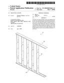
[0008]FIG. 1 is an environmental, perspective view of a track wall system according to the present invention.
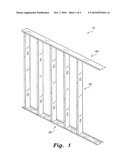
[0009]FIG. 2 is an enlarged partial perspective view of the track wall system according to the present invention.
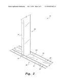
[0010]FIG. 3 is a top view of the track of a track wall system according to the present invention.
[0011]Similar reference characters denote corresponding features consistently throughout the attached drawings.
DETAILED DESCRIPTION OF THE PREFERRED EMBODIMENTS
[0012]The present invention relates to a track wall system for framing a wall in a secure, fast and reliable manner. As shown in FIGS. 1 and 2, the track wall system 10 includes an elongated bottom track 20, an elongated top track 40, wall studs 30 disposed between the top and bottom tracks 40, 20 and spaced along the length thereof, and a plurality of pairs of stud holding notches 25, 25 that securely hold the respective stud in place. The tracks may be constructed from steel or any other similar material suitable for framing. The studs may be made from wood, structural steel or other material suitable to form the frame and optionally support loads in a load-bearing setup.
[0013]The following describes more details of the bottom track 20 and installation of the stud 30. It is to be understood that the top track 40 is similarly constructed. Referring to FIG. 2, the elongated bottom track 20 includes a base 23 and opposite sidewalls 21, 22 extending from the base 23 to thereby form a substantial U-shape in cross section. The space between the sidewalls 21, 22 form a stud layout trough whereby the studs 30 may be laid at predetermined intervals. Each of the sidewalls 21, 22 have a plurality of pairs of discontinuous stud holding notches 25, 25 formed on the edge of the sidewall away from the base 23. The spacing between each pair of notches 25, 25 conform to standard layout spacing of studs, e.g. 8, 16, 24 in. Each notch 25 is formed by making a cut along the top edge of the sidewall 21 and bending a portion the sidewall inwardly toward the trough at an angle. The bent portion of the sidewall subsequently forms a stud holding projection 26. The spacing between the notches 25, 25 correspond to the thickness of the stud 30, and the opposite sidewall 22 also includes similarly formed notches 25, 25 in alignment with the ones on the sidewall 21 to thereby securely hold the stud 30 therebetween.
[0014]It is noted that the notches 25, 25 of each pair have the projections 26, 26 extending in mirror opposite directions, i.e. one of the projections 26, 26 is bent toward the right while the other is bent toward the left. See FIG. 3. The purpose thereof is two fold. On the one hand, the projections from both sidewalls stabilize centering of the stud 30 in the track 20, and on the other hand, the configuration of the angled projections function as a guide to slide the stud 30 in place.
[0015]The following describes how the track wall system 10 is used. To form a wall frame, the user places the bottom track 20 on the floor or work surface. The track 20 is already prefabricated to include the stud holding notches 25, 25 spaced at the proper predefined intervals along the track 20. The user then slides a stud 30 between opposing pairs of notches 25, 25 on the sidewalls 21, 22 and snaps the stud in place. This process is repeated along the length of track 20. Preferably, each stud 30 is secured to the bottom track 20 by a fastener 12. Once the studs 30 have been properly centered and laid out along bottom track 20, the top track 40 may be slidably fit over the tops of the studs 30. The top track 40 may optionally be secured to the studs by fasteners 12. An unfastened top track 40 allows for some deflection and movement of the wall frame to compensate for irregular levels or loads. The completed frame is then mounted at a predefined location in preparation for subsequent drywall installation or wall covering.
[0016]Another method of using the track wall system 10 includes initial installment of both the top and bottom tracks 40, 20. Once the tracks 20, 40 are leveled and installed, the studs 30 may snap fit into place along the tracks 20, 40.
[0017]Thus, it can be seen that the track wall system 10 allows for a fast, accurate and reliable assembly of a wall frame. The track wall system 10 eliminates much of the time and handling required for laying out the wall frame on-site due to the prefabricated layout present in the track wall system 10. In the construction industry, the timesaving of the track wall system 10 provides a significant financial impact.
[0018]It is noted that the track wall system 10 may encompass a variety of alternatives to the various features thereof. For example, the track wall system 10 is not limited in application to walls per se. It may be used for other framing applications such as doors, windows, mantles, etc. Moreover, the track wall system 10 may be configured to accommodate a variety of stud dimensions and spacing. The tracks and the notches thereon may be molded or preformed. The projections 26 may also be of a different shape than the triangular one shown in the drawings. For example, the projections 26, 26 may be square or rectangular shape as long as they function as a holder and a stud installation guide.
[0019]It is to be understood that the present invention is not limited to the embodiments described above, but encompasses any and all embodiments within the scope of the following claims.
Claims:
1. A track wall system, comprising:an elongated bottom track and top
track, each of the tracks having a base and opposing sidewalls extending
from the base to define a stud layout trough therebetween, each of the
sidewalls having an elongated edge opposite the base and at least one
pair of stud holding notches defined in each of the edges;a projection
extending from each of the notches; andat least one stud disposed between
opposing pairs of stud holding notches and between the top and bottom
tracks, each of the opposing pair of stud holding notches being spaced at
regular predefined layout intervals along each of the sidewalls to
thereby eliminate on-site measuring of a particular wall frame layout.
2. The track wall system according to claim 1 wherein each of the tracks is substantially U-shaped in cross section.
3. The track wall system according to claim 1, wherein the notches in each of the pairs are spaced apart by the thickness of the stud.
4. The track wall system according to claim 1, wherein each said projection extends inwardly toward the stud layout trough at an angle.
5. The track wall system according to claim 1, wherein each said projection of said at least one pair of notches is disposed in mirror opposite configuration with respect to each other.
6. The track wall system according to claim 1, wherein each said projection is substantially triangular.
Description:
BACKGROUND OF THE INVENTION
[0001]1. Field of the Invention
[0002]The present invention relates to wall framing assemblies, more particularly, a track wall system that reduces time required to set up a wall frame.
[0003]2. Description of the Related Art
[0004]In commercial and residential construction, wall framing has long been a tedious and exacting task, both for load bearing and non-load bearing walls. Each track of the wall frame must be accurately measured and marked for placement of studs at regular intervals along the length thereof. This is a repetitive and time-consuming process, which results in sub-optimal financial spending for time worked and the time required for the resultant structure. One method of solving this issue has been to use a wall frame system that includes tracks with regularly spaced shaped indentions that may be mated to corresponding shaped indentions on the to be installed steel studs. However, this type of system requires more effort and additional steps due to the snap fit or mated nature of the connection between the track and stud indentions and/or working of the track walls to fit the indentions thereon to the ones on the studs. Thus, while time may be saved in the initial layout of the studs on the tracks, the time spent to install the studs reduces the net savings in time.
[0005]Thus, a track wall system solving the aforementioned problems is desired.
SUMMARY OF THE INVENTION
[0006]The track wall system includes at least one elongated track having a base and opposite sidewalls together defining a stud layout trough therebetween, each of the sidewalls includes a plurality of pairs of discontinuous stud holding notches disposed at regular intervals along the length of the track, each pair of stud holding notches defines a space therebetween adapted to hold a stud, a plurality of studs disposed between opposing pairs of stud holding notches, and each notch includes projections that securely holds the stud for fast installation of a wall frame.
[0007]These and other features of the present invention will become readily apparent upon further review of the following specification and drawings.
BRIEF DESCRIPTION OF THE DRAWINGS
[0008]FIG. 1 is an environmental, perspective view of a track wall system according to the present invention.
[0009]FIG. 2 is an enlarged partial perspective view of the track wall system according to the present invention.
[0010]FIG. 3 is a top view of the track of a track wall system according to the present invention.
[0011]Similar reference characters denote corresponding features consistently throughout the attached drawings.
DETAILED DESCRIPTION OF THE PREFERRED EMBODIMENTS
[0012]The present invention relates to a track wall system for framing a wall in a secure, fast and reliable manner. As shown in FIGS. 1 and 2, the track wall system 10 includes an elongated bottom track 20, an elongated top track 40, wall studs 30 disposed between the top and bottom tracks 40, 20 and spaced along the length thereof, and a plurality of pairs of stud holding notches 25, 25 that securely hold the respective stud in place. The tracks may be constructed from steel or any other similar material suitable for framing. The studs may be made from wood, structural steel or other material suitable to form the frame and optionally support loads in a load-bearing setup.
[0013]The following describes more details of the bottom track 20 and installation of the stud 30. It is to be understood that the top track 40 is similarly constructed. Referring to FIG. 2, the elongated bottom track 20 includes a base 23 and opposite sidewalls 21, 22 extending from the base 23 to thereby form a substantial U-shape in cross section. The space between the sidewalls 21, 22 form a stud layout trough whereby the studs 30 may be laid at predetermined intervals. Each of the sidewalls 21, 22 have a plurality of pairs of discontinuous stud holding notches 25, 25 formed on the edge of the sidewall away from the base 23. The spacing between each pair of notches 25, 25 conform to standard layout spacing of studs, e.g. 8, 16, 24 in. Each notch 25 is formed by making a cut along the top edge of the sidewall 21 and bending a portion the sidewall inwardly toward the trough at an angle. The bent portion of the sidewall subsequently forms a stud holding projection 26. The spacing between the notches 25, 25 correspond to the thickness of the stud 30, and the opposite sidewall 22 also includes similarly formed notches 25, 25 in alignment with the ones on the sidewall 21 to thereby securely hold the stud 30 therebetween.
[0014]It is noted that the notches 25, 25 of each pair have the projections 26, 26 extending in mirror opposite directions, i.e. one of the projections 26, 26 is bent toward the right while the other is bent toward the left. See FIG. 3. The purpose thereof is two fold. On the one hand, the projections from both sidewalls stabilize centering of the stud 30 in the track 20, and on the other hand, the configuration of the angled projections function as a guide to slide the stud 30 in place.
[0015]The following describes how the track wall system 10 is used. To form a wall frame, the user places the bottom track 20 on the floor or work surface. The track 20 is already prefabricated to include the stud holding notches 25, 25 spaced at the proper predefined intervals along the track 20. The user then slides a stud 30 between opposing pairs of notches 25, 25 on the sidewalls 21, 22 and snaps the stud in place. This process is repeated along the length of track 20. Preferably, each stud 30 is secured to the bottom track 20 by a fastener 12. Once the studs 30 have been properly centered and laid out along bottom track 20, the top track 40 may be slidably fit over the tops of the studs 30. The top track 40 may optionally be secured to the studs by fasteners 12. An unfastened top track 40 allows for some deflection and movement of the wall frame to compensate for irregular levels or loads. The completed frame is then mounted at a predefined location in preparation for subsequent drywall installation or wall covering.
[0016]Another method of using the track wall system 10 includes initial installment of both the top and bottom tracks 40, 20. Once the tracks 20, 40 are leveled and installed, the studs 30 may snap fit into place along the tracks 20, 40.
[0017]Thus, it can be seen that the track wall system 10 allows for a fast, accurate and reliable assembly of a wall frame. The track wall system 10 eliminates much of the time and handling required for laying out the wall frame on-site due to the prefabricated layout present in the track wall system 10. In the construction industry, the timesaving of the track wall system 10 provides a significant financial impact.
[0018]It is noted that the track wall system 10 may encompass a variety of alternatives to the various features thereof. For example, the track wall system 10 is not limited in application to walls per se. It may be used for other framing applications such as doors, windows, mantles, etc. Moreover, the track wall system 10 may be configured to accommodate a variety of stud dimensions and spacing. The tracks and the notches thereon may be molded or preformed. The projections 26 may also be of a different shape than the triangular one shown in the drawings. For example, the projections 26, 26 may be square or rectangular shape as long as they function as a holder and a stud installation guide.
[0019]It is to be understood that the present invention is not limited to the embodiments described above, but encompasses any and all embodiments within the scope of the following claims.
User Contributions:
Comment about this patent or add new information about this topic:
Images included with this patent application:
 |  |
 |  |
| Similar patent applications: | |
| Date | Title |
|---|---|
| 2013-03-28 | Stackable wall block system |
| 2009-07-30 | Integrated wall system |
| 2013-09-26 | Self-reinforced masonry blocks, walls made from self-reinforced masonry blocks, and method for making self-reinforced masonry blocks |
| 2008-12-04 | Interior wall system |
| 2010-07-01 | Integrated walkway system |
| New patent applications in this class: | |
| Date | Title |
|---|---|
| 2015-04-23 | Truss mount bracket for roof anchors and related systems and methods |
| 2014-10-30 | Anchor rail |
| 2014-09-18 | Support structures on roofs |
| 2014-09-11 | Cast-in anchor system |
| 2014-06-26 | Roof tile crown support |
| Top Inventors for class "Static structures (e.g., buildings)" | |
| Rank | Inventor's name |
|---|---|
| 1 | Darko Pervan |
| 2 | Gregory F. Jacobs |
| 3 | Husnu M. Kalkanoglu |
| 4 | Ronald P. Hohmann, Jr. |
| 5 | Mark Cappelle |