Patent application title: VACUUM COVER
Inventors:
Yong-Kwon Lee (Seoul, KR)
Assignees:
LEE & LEE HI-TECH. CO., LTD.
IPC8 Class: AB65D5100FI
USPC Class:
220212
Class name: Receptacles closures combined or convertible
Publication date: 2010-09-23
Patent application number: 20100237071
uum cover, which is coupled to an object to
define storage space isolated from the exterior, and moves in a direction
that reduces the volume of the storage space due to its elasticity, thus
discharging air from the storage space, therefore improving sealing
ability and preventing food stored in the storage space from contacting
the air. The vacuum cover is made of elastomer, such as silicone rubber,
and integrally has a member for air-tightly contacting an object or a
valve for supplying or exhausting the air. The vacuum cover includes an
elastic body, which isolates storage space from an exterior and is
deformed so that air is exhausted from or supplied to the storage space,
and a valve provided at a predetermined position on the body to discharge
and/or supply the air from and/or to the storage space.Claims:
1. A vacuum cover, comprising:an elastic body, isolating storage space
from an exterior, and deformed so that air is exhausted from or supplied
to the storage space; anda valve provided at a predetermined position in
the body to discharge and/or supply the air from and/or to the storage
space.
2. The vacuum cover according to claim 1, wherein the valve comprises a protruding press part, and an air inlet/exhaust part formed by incising an upper surface of the press part.
3. The vacuum cover according to claim 2, wherein an exhaust passage facing the air inlet/exhaust part is shaped so that an upper portion of the exhaust passage is narrow and a lower portion of the exhaust passage is wide.
4. The vacuum cover according to claim 1, wherein the valve comprises:a coupling part inserted into a valve mounting hole of the body;a support part contacting a lower surface of the body, and positioned under the coupling part; anda shutting part placed on an upper surface of the body, and shutting an air discharge hole formed in the body.
5. The vacuum cover according to claim 4, wherein the coupling part of the valve has a length such that it is movable up and down relative to the body.
6. The vacuum cover according to claim 4, wherein the valve further comprises a grip part provided on an upper portion of the shutting part.
7. The vacuum cover according to claim 1, wherein a sealing protrusion is provided at a predetermined position on the body that contacts a corresponding object, which defines the storage space isolated from the exterior along with the body, andan air layer is defined between the sealing protrusion and the corresponding object.
8. The vacuum cover according to claim 1, wherein removal prevention parts are provided on a predetermined position on the corresponding object, defining the storage space, isolated from the exterior along with the body, and a predetermined position on the body, which contacts the corresponding object, and are coupled to each other through a male-female-coupling method.
9. The vacuum cover according to claim 1, wherein a skirt extends from an outer edge of the body.
10. The vacuum cover according to claim 1, wherein the body has a dome shape.
11. The vacuum cover according to claim 10, wherein a thin part is provided inside the edge of the body contacting the corresponding object which defines the storage space, isolated from the exterior along with the body.
12. The vacuum cover according to claim 1, wherein a depressed part is provided on the body to be positioned around the valve, and prevents the valve from projecting out.
13. The vacuum cover according to claim 1, wherein the body is formed to have a single structure through injection molding, and is made of elastomer.
14. The vacuum cover according to claim 1, wherein the body and the valve are integrated into a single structure through injection molding, and are made of elastomer.
15. The vacuum cover according to claim 2, wherein the air inlet/exhaust part of the valve has a diagonal shape.
16. The vacuum cover according to claim 3, wherein the air inlet/exhaust part of the valve has a diagonal shape.Description:
TECHNICAL FIELD
[0001]The present invention relates, in general, to a vacuum cover, which is coupled to an object, namely, a vessel, such as a dish or a bowl, to define a storage space isolated from the exterior, and which moves in a direction of reducing the volume of the storage space due to its elasticity, thus discharging air from the storage space, therefore improving sealing ability and preventing food stored in the storage space from contacting air so that the food can be kept for a long time and, more particularly, to a vacuum cover, which is made of elastomer, such as silicone rubber, and which integrally has a member for air-tightly contacting an object or a valve for supplying or exhausting the air, unlike a conventional vacuum cover manufactured by assembling individual members with each other, thus preventing the residue of food from being caught between the members and preventing the food from accumulating between the members, therefore being sanitary, and which does not use synthetic resin, unlike conventional covers for food vessels, thus preventing the generation of endocrine disruptors which is currently an issue, therefore appealing to consumers.
[0002]Recently, a vacuum vessel which is evacuated to create a vacuum in the vessel, in addition to serving as an airtight vessel, has appealed to consumers. Air is discharged from the vessel, which is used to store food, for example, fruit, vegetables, or leftover side dishes, thus delaying the oxidation of the food by aerobic microorganisms, therefore extending the expiration period of the stored food.
[0003]Further, air is exhausted from the vacuum vessel, thus preventing food from emitting odors and preventing the odors from permeating other food.
BACKGROUND ART
[0004]Vacuum vessels are classified into a vacuum vessel from which air is exhausted using a separately provided vacuum device, such as a motor pump, and a vacuum vessel which has an exhaust piston, such as a syringe, on the vessel itself. The former vacuum vessel is disclosed in Korean U.M. Registration No. 0395836 which was filed by An JunYoung, was registered on Sep. 7, 2005, and is entitled .left brkt-bot.Cover For Vacuum Vessel.right brkt-bot..
[0005]The latter vacuum vessel is disclosed in Korean U.M. Registration No. 0402438, which was filed by Kim HyungJun et al., was registered on Nov. 24, 2005, and is entitled .left brkt-bot.Vacuum Packing Vessel.right brkt-bot..
[0006]However, the above-mentioned vacuum vessels have a drawback in that they are complicated to use. Thus, the vacuum vessels substitute for simple airtight vessels, and have not achieved great commercial success.
[0007]In addition to the vacuum vessels disclosed in the two documents, an elastic cover has been proposed. The vacuum level achieved using the elastic cover is lower than the vacuum level achieved by the above vacuum vessels, which use the separately provided vacuum devices. However, the main object of the elastic cover is to afford convenient use. Further, the elastic cover can discharge the air from a vessel, thus delaying the oxidation of food.
[0008]Such an elastic cover is disclosed in Korean U.M. Registration No. 0389341, which was filed by Kim JaeYeon, was registered on Jul. 1, 2005, is entitled .left brkt-bot.Airtight Cover for Compressing and Evacuating Vessel.right brkt-bot., and includes a hard upper compressing cover and a lower lap cover made of silicone material, and Korean Patent No. 0526358, which was filed by SaeSam, Inc., was registered on Oct. 28, 2005, is entitled .left brkt-bot.Cover for Vessels.right brkt-bot., and has a corrugated part for flexibility. The elastic cover according to the cited documents moves in a direction of reducing the volume of storage space defined by the coupling of the vessel with the cover, thus discharging air from the storage space.
[0009]However, the elastic vacuum cover, performing the pumping function, must satisfy the following requirements so as to create new demand or substitute for an existing airtight vessel, for example, a vessel disclosed in Korean Patent No. 0452886, which was filed by HanaCobi, Inc., was registered on Oct. 5, 2004, and is entitled .left brkt-bot.Airtight Food Vessel Having Handle.right brkt-bot..
[0010]That is, the food vessel and cover, which have superior sealing ability, contain no material that produces endocrine disruptors, that is, so-called "environmental hormones", for example, polystyrene oligomers of a plastic product, bisphenol A, a phthalic acid compound, used as a plasticizer, and others, and in addition, do not use organic synthetic resin, are required.
[0011]Meanwhile, a vessel, which is made of heat-resistant glass, so that it does not produce environmental hormones, has come onto the market and appealed to consumers. However, the cover is still made of synthetic resin, in consideration of a cost and sealing ability.
DISCLOSURE
Technical Problem
[0012]Accordingly, the present invention has been made keeping in mind the above problems occurring in the prior art, and the present invention provides a vacuum cover, which does not produce environmental hormones, ensures the sealing ability of an existing airtight vessel, and creates a vacuum in storage space, thus preventing the oxidation of food.
[0013]To this end, an object of the present invention is to provide a vacuum cover, which is made of elastomer, especially silicone rubber, so that no environmental hormones are produced, and which has high heat resistance, so that the vacuum cover is not deformed, or the sealing ability of the vacuum cover is not lowered but is maintained, thus preventing the leakage of food, even when the vacuum cover is put into a microwave oven or when hot food is covered with the vacuum cover.
[0014]Another object of the present invention is to provide various models of vacuum covers, which are applicable to various objects, that is, a bowl-type vessel, a dish-type vessel, or a table covered with a glass panel.
[0015]A further object of the present invention is to provide a vacuum cover, in which a skirt or a sealing protrusion provided on a surface contacting a corresponding object to increase the sealing ability is integrated with a cover body, and in addition, a valve for supplying or exhausting the air into or from storage space is integrated with the cover body, thus preventing food from being caught or accumulating in a gap between a packing ring and a cover, therefore preventing the vacuum cover from being soiled and being unsanitary, unlike a conventional airtight vessel, which is constructed so that the packing ring is coupled to (attached to or press-fitted into) the cover.
[0016]Yet another object of the present invention is to provide a vacuum cover, in which respective parts are made of material having the same physical properties, but have different thicknesses, thus increasing sealing ability (thick part--skirt portion), ensuring the sealing ability through rapid engagement and strong coupling force when a valve is opened and thereafter is restored to its original position (thick part--united valve), and allowing a part to change its shape when an evacuating operation is performed (thin part--edge portion), therefore allowing the part to come into contact with a corresponding object once again, in addition to the original contact of the edge with the object. As such, different thicknesses are provided to the respective parts, thus providing various functions.
Technical Solution
[0017]In order to accomplish the objects, the present invention provides a vacuum cover, including an elastic body, isolating storage space from an exterior, and deformed so that air is exhausted from or supplied to the storage space; and a valve provided at a predetermined position in the body to discharge and/or supply the air from and/or to the storage space.
[0018]For a united valve, the valve includes a protruding press part, and an air inlet/exhaust part formed by incising an upper surface of the press part.
[0019]Preferably, an exhaust passage facing the air inlet/exhaust part is shaped so that an upper portion of the exhaust passage is narrow and a lower portion of the exhaust passage is wide.
[0020]For a disunited valve, the valve includes a coupling part inserted into a valve mounting hole of the body, a support part contacting a lower surface of the body and positioned under the coupling part, and a shutting part placed on an upper surface of the body and shutting an air discharge hole formed in the body.
[0021]The coupling part of the valve has a length such that it is movable up and down relative to the body.
[0022]The valve further includes a grip part provided on an upper portion of the shutting part.
[0023]In order to enhance sealing ability, a sealing protrusion is provided at a predetermined position on the body that contacts a corresponding object, which defines the storage space isolated from the exterior along with the body, and an air layer is defined between the sealing protrusion and the corresponding object. Further, removal prevention parts are provided on a predetermined position on the corresponding object, defining the storage space, isolated from the exterior along with the body, and a predetermined position on the body, which contacts the corresponding object, and are coupled to each other through a male-female-coupling method. Preferably, a skirt extends from an outer edge of the body.
[0024]A thin part is provided inside the edge of the body contacting the corresponding object which defines the storage space, isolated from the exterior along with the body, so that the thin part additionally contacts the corresponding object, thus increasing sealing ability.
ADVANTAGEOUS EFFECTS
[0025]As described above, according to the present invention, a vacuum cover is made of elastomer, especially silicone rubber, so that no environmental hormones are produced, and which has high heat resistance, so that the vacuum cover is not deformed, or the sealing ability of the vacuum cover is not lowered but is maintained, thus preventing the leakage of food, even when the vacuum cover is put into a microwave oven or when hot food is covered with the vacuum cover. The present invention provides various models of vacuum covers, which are applicable to various objects, that is, a bowl-type vessel, a dish-type vessel, or a table covered with a glass panel. Further, a skirt or a sealing protrusion provided on a surface contacting a corresponding object to increase the sealing ability is integrated with a cover body, and in addition, a valve for supplying or exhausting the air into or from storage space is integrated with the cover body, thus preventing food from being caught or accumulating in a gap between a packing ring and a cover, therefore preventing the vacuum cover from being soiled and being unsanitary, unlike a conventional airtight vessel, which is constructed so that the packing ring is coupled to (attached to or press-fitted into) the cover. Further, respective parts are made of material having the same physical properties, but have different thicknesses, thus increasing sealing ability (thick part--skirt portion), ensuring the sealing ability through rapid engagement and strong coupling force when a valve is opened and thereafter is restored to its original position (thick part--united valve), and allowing a part to change its shape when an evacuating operation is performed (thin part--edge portion), therefore allowing the part to come into contact with a corresponding object once again, in addition to the original contact of the edge with the object. As such, different thicknesses are provided to the respective parts, thus providing various functions.
DESCRIPTION OF DRAWINGS
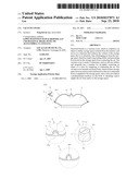
[0026]FIG. 1 is a sectional view showing the state where a dome-type vacuum cover (having a united valve) according to the first aspect of the present invention is coupled to a dish-type vessel which is one kind of corresponding object and defines storage space along with the vacuum cover;
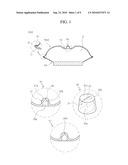
[0027]FIG. 2 is a sectional view illustrating the operation of supplying external air so as to separate the vacuum cover and the vessel, which are coupled to each other as shown in FIG. 1;
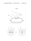
[0028]FIG. 3 is a view illustrating the vacuum cover of FIG. 1, according to the first aspect of the present invention, in a plan view and a bottom view;
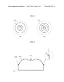
[0029]FIG. 4 is a sectional view showing the state where the dome-type vacuum cover (having the united valve) according to the first aspect of the present invention is applied to a bowl-type vessel;
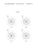
[0030]FIG. 5 is a schematic bottom view showing modifications of an air inlet/exhaust part of the united valve of the vacuum cover;
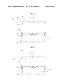
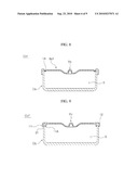
[0031]FIGS. 6, 7, 8, and 9 are sectional views showing several modifications of a flat-type vacuum cover (having a united valve) according to the second aspect of the present invention, and showing the state where the flat-type vacuum cover is coupled to a bowl-type vessel;
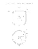
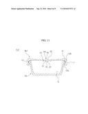
[0032]FIGS. 10 and 11 are a plan view and a sectional view showing the state where a vacuum cover having a disunited valve according to the third aspect of the present invention is coupled to a bowl-type vessel; and
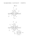
[0033]FIG. 12 is a sectional view showing important parts of a vacuum cover having a disunited valve, in which the valve of the vacuum cover is different from the valve of FIG. 11 in that it is provided with a grip part.
DESCRIPTION OF REFERENCE CHARACTERS OF IMPORTANT PARTS
TABLE-US-00001 [0034]Ccd, Cif, Ccf, Ccf': vacuum cover Bcd, Bif, Bcf: cover body 11: skirt 12: removal prevention part 13: sealing protrusion 13A: flange 13a: air layer 14: thin part 15: depressed part 16: valve mounting hole 17, 17A: air discharge holes Vu, Vd: valve 21: protruding press part 21a: thick part 22, 22A: air inlet/exhaust part 22a: exhaust passage 23: shutting part 23A: grip part 25: support part 25A: exhaust slit 27: coupling part
Best Mode
[0035]Hereinafter, the present invention will be described in detail with reference to the accompanying drawings.
[0036]The same reference numerals throughout the drawings denote elements having the same function. If there is no special mention otherwise, the elements denoted by the reference numerals are to be comprehended as being elements complying with the above-mentioned reference scheme.
[0037]A cover according to the present invention may be classified into a dome-type cover and a flat-type cover according to the shape thereof.
[0038]Further, a corresponding object, which is coupled to the vacuum cover according to the present invention and defines a storage space isolated from the exterior, is classified into an inscribed-type object and a circumscribed-type object according to the form of the contact of the object with the edge of the cover. The inscribed-type object is constructed so that the edge of the cover contacts the inner surface of the object. The circumscribed-type object is constructed so that the edge of the cover contacts the outer surface of the object (therefore, terms `inscribed` and `circumscribed` are defined on the basis of the object). The reference numerals for the cover are set according to the above reference-scheme (Ccd, Cif, Ccf, and Ccf').
[0039]Valves which are used to exhaust the air from storage space or to supply the air into the storage space are classified into a united valve and a disunited valve, which are denoted by different reference numerals Vu and Vd. The united valve is integrated with the cover through injection molding. The disunited valve is manufactured separately from the cover through double injection molding, and is coupled to the cover.
[0040]In the present invention, an article coupled to the vacuum cover may be a vessel, such as a bowl or a dish. A dome-type cover Ccd of FIG. 1 covers a smooth surface (e.g.: glass panel) provided on a table, thus defining storage space. In order to include all articles which may be covered with the vacuum cover, the term `corresponding object` is used herein.
[0041]Herein, the term `skirt` 11 denotes a part which extends from an edge of a body of each model of vacuum cover and surrounds the outer surface of the vessel.
[0042]The body and/or the valve of the vacuum cover according to the present invention use elastomer, especially silicone rubber, which does not produce environmental hormones and has high heat resistance.
[0043]Owing to the elasticity of the material, the vacuum cover can serve as a pump for exhausting air from the storage space or supplying air into the storage space.
[0044]First, a vacuum cover Ccd of FIGS. 1, 2, 3, 4, and 5 is provided with a dome-type vacuum cover, according to the first aspect of the present invention, and a united valve.
[0045]Referring to FIGS. 1 and 2, the vacuum cover Ccd is the model which covers a dish-type vessel or completely covers a vessel that contains food therein and is placed on a glass panel of a dining table.
[0046]Referring to the drawings, a cover body Bcd has a dome shape, and a skirt 11 is provided on an edge of the body to surround the lower portion of the outer portion of a dish-type vessel Cd. Further, a removal prevention part 12 is provided at a predetermined position on the body, and is coupled to the vessel through a male-female-coupling method.
[0047]The cover body Bcd defines storage space S isolated from the exterior, along with a corresponding object, especially, the dish-type vessel Cd.
[0048]When the cover body Bcd is pressed, so that air is discharged from the storage space S through the edge of the body or through a valve Vu, the volume of the storage space is reduced. At this time, the cover body made of the elastomer is contracted.
[0049]As the air is discharged from the storage space S, the coupling force of the dish-type vessel Cd with the cover is increased (particularly, even if vertical force acts on the cover, it is difficult to separate the cover from the vessel because of the coupling construction of the dish-type vessel, the removal prevention part 12 of the body, and the skirt 11).
[0050]Since the cover body contracts, a part 14 which is thinner than other parts arranged inside the edge of the body Bcd contacts the upper surface of the dish-type vessel Cd. Thus, the thin part 14 can perform a double sealing function along with the removal prevention part 12.
[0051]A united valve Vu, which is formed through injection molding, is integrally provided on the upper portion of the center of the body Bcd. A depressed part 15 is formed around the valve to prevent the valve Vu from projecting out.
[0052]The valve Vu may be used to discharge and/or supply gas from and/or to the storage space S. When the valve Vu and the body Bcd of the dome-type cover Ccd are pressed, air is discharged from the storage space through the gap between the edge of the body and the vessel Cd. As necessary, the valve may be mainly used to supply gas to the storage space, and the gas may be discharged through the gap between the edge of the body and the vessel Cd by pressing the body Bcd.
[0053]The valve Vu includes a protruding press part 21 and an air inlet/exhaust part 22. The protruding press part is surrounded by the depressed part 15 of the body and maintains a height which is similar to that of the upper surface of the body. The upper surface of the press part 21 is incised, thus providing the air inlet/exhaust part 22.
[0054]As shown in circle "A" of FIG. 1, the air inlet/exhaust part 122 is formed by vertically incising the upper surface of the press part, and extends in a straight line, as shown in the plan view of FIG. 3A and the bottom view of FIG. 3B.
[0055]When a user desires to separate the cover Ccd, according to the first aspect, from the dish-type vessel Cd, the press part 21 is pressed. Especially, as shown in FIG. 2, both ends of the air inlet/exhaust part 22 are pressed in the direction of the incision to open it. In this state, air is supplied to the storage space, so that the cover can be separated from the vessel.
[0056]The press part 21 of the valve Vu has the shape of a truncated cone. An exhaust passage 22a facing the air inlet/exhaust part 22 is shaped such that the upper portion thereof is narrow and the lower portion thereof is wide. In a detailed description, as shown in circle "B" of FIG. 1, the exhaust passage has the shape of a house having a roof.
[0057]Since the exhaust passage 22a is shaped such that the upper portion thereof is narrow and the lower portion thereof is wide, the portion adjacent to the air inlet/exhaust part 22 has a thicker wall, thus providing a thick part 21a. Thus, elasticity easily acts in the direction in which the air inlet/exhaust part 22 of the valve closes, so that rapid engagement and strong coupling force are ensured when the valve is opened and thereafter is restored to its original state.
[0058]FIG. 4 shows the state where the vacuum cover of FIG. 1 according to the first aspect is applied to a bowl-type vessel Cb. The thin part 14 is provided around the edge of the body Bcd. Thus, when the storage space is evacuated, the lower surface of the thin part contacts the inner surface of the upper end of the vessel Cb, so that sealing ability is increased.
[0059]Further, circle "C" of FIG. 1 shows a modification of the vacuum cover Ccd according to the first aspect of the present invention. As shown in the drawing, an air inlet/exhaust part 22A of the valve Vu is incised diagonally rather than vertically, thus more effectively preventing the vertical flow of air.
[0060]FIG. 5 shows various air inlet/exhaust parts 22A of the valve. FIG. 5A shows a toothed air inlet/exhaust part, FIG. 5B shows a curved air inlet/exhaust part, FIG. 5C shows an air inlet/exhaust part which is incised to have two lines, and FIG. 5D shows an air inlet/exhaust part which is incised to have two brackets. These air inlet/exhaust parts improve sealing ability when being closed.
[0061]FIG. 6 shows a flat-type vacuum cover Cif according to the second aspect of the present invention. The vacuum cover is provided with a united valve Vu, and is constructed so that the edge of the vacuum cover contacts the inner surface of a bowl-type vessel Cd.
[0062]Referring to FIG. 6, a cover body Bif has a depressed part 15 around the valve Vu. A sealing protrusion 13 is provided on the body in such a way as to contact the inner surface of the bowl-type vessel Cd, which is one kind of corresponding object. Further, an air layer 13a is defined between the sealing protrusion and the vessel Cd, so that the sealing ability is improved.
[0063]The air layer 13a is surrounded with a flange 13A and the sealing protrusion 13 of the cover body Bif and the inner wall of the vessel Cb. When the sealing protrusion 13 comprises two or more sealing protrusions, another air layer is formed by the protrusions and the inner wall of the vessel.
[0064]Moreover, the flange 13A of the cover body protrudes further out of the vessel, thus serving as a grip part when the cover is separated from the vessel. The flange 13A is thicker than other parts. This construction reduces the consumption of material and provides sufficient support force to prevent the cover from entering the vessel even when the cover, placed on the upper end of the vessel, is pressed to create a vacuum in the storage space S.
[0065]When the cover body Bif is pressed to discharge air from the storage space S, the air is discharged through the valve and/or the gap between the edge of the body and the vessel.
[0066]Unlike the vacuum cover of FIG. 6, FIG. 7 shows a vacuum cover which is constructed to cover the outer surface of the bowl-type vessel Cb. A sealing protrusion 13 and an air layer 13a are formed to be suitable for the modified vacuum cover.
[0067]Unlike the vacuum cover of FIG. 7, FIG. 8 shows a vacuum cover which is constructed so that a thin part 14 is provided around an edge 13A. Thus, when storage space S is evacuated, the thin part 14 comes into close contact with the inner wall of the upper portion of the bowl-type vessel Cb.
[0068]The vacuum cover of FIG. 9 has a shape that is intermediate between the vacuum covers of FIGS. 6 and 7, and is different from the vacuum covers of FIGS. 6 and 7 in that it is provided with an extension sleeve 11A contacting the inner surface of the vessel, in addition to having a skirt 11 that surrounds the outer surface of the vessel Cb (Reference numeral 12a denotes a finger insertion gap).
[0069]FIGS. 10 and 11 are a plan view and a sectional view showing the state where a vacuum cover having a disunited valve Vd according to the third aspect of the present invention is coupled to a bowl-type vessel.
[0070]FIGS. 10A and 10B show a rectangular cover and a circular cover Ccf, which are suitable for rectangular and circular bowl-type vessels.
[0071]As shown in FIGS. 10 and 11, a continuous or discontinuous male removal prevention part 31 is provided on the outer circumference of the upper portion of the bowl-type vessel Cb. A female removal prevention part 12 is provided on a body Bcf of the cover Ccf in such a way as to be positioned on the inner circumference of a skirt 11, and engages with the male removal prevention part 31.
[0072]Further, the inner surface of the lower portion of the skirt 11 is inclined, and the outer wall of the vessel Cb is also inclined. Thus, when the cover is coupled to the vessel, the finger insertion gap 12a is defined in a junction between the cover and the vessel, so that it is easy to separate the cover from the vessel.
[0073]An edge and the skirt 11 of the body Bcf of the cover Ccf are thicker than inner portions of the cover body, thus allowing the cover to be firmly coupled to the vessel, therefore preventing the cover from being separated from the vessel, and increasing sealing ability.
[0074]Meanwhile, a valve mounting hole 16 is formed in the center of the body Bcf, and four air discharge holes 17 are formed around the valve mounting hole 16.
[0075]The disunited valve Vd includes a coupling part 27, which is inserted into the valve mounting hole 16 of the body Bcf, a support part 25, which contacts the lower surface of the body and is positioned under the coupling part, and a shutting part 23, which is positioned on the upper surface of the body and shuts the air discharge holes 17 formed in the body. Such a valve is provided in a depressed part of the body, so that the valve does not protrude outwards.
[0076]When the body Bcf of the cover Ccf, coupled to the vessel, is pressed, so that air is discharged from the storage space S, the air is mainly discharged through the air discharge holes 17 because of the position of the shutting part 23.
[0077]Further, in order to supply air to the storage space in advance before the separation of the cover from the vessel, a user has only to lift the shutting part 23 of the valve.
[0078]FIGS. 12A and 12B are sectional views showing important parts of vacuum covers having disunited valves. The valves are different from the valve of FIG. 11 in that they have grip parts.
[0079]The valve Vd of FIG. 12A is different from the valve of FIG. 11 in that a grip part 23A simply protrudes from the valve.
[0080]The valve Vd of FIG. 12B is different from the valve of FIG. 11 in that it has a grip part 23A, and in that a coupling part 27 has length such that it is movable up and down relative to a body Bcf. Further, an air discharge hole 17A of the body Bcf of FIG. 12B collaterally serves as a valve mounting hole. Air is discharged through an exhaust slit 25A formed in a support part 25 of the valve Vd and the air discharge hole 17A of the body. When a user desires to discharge air from the storage space or supply air to the storage space, the grip part 23A is pulled, so that the shutting part 23 is separated from the body Bcf.
[0081]Preferably, the valve of FIG. 12B is constructed so that undesirable rotation thereof is impossible, so that the exhaust slit 25A is always aligned with the air discharge hole 17A of the body. To this end, the coupling part 27 of the valve and the air discharge hole 17 of the body are formed such that they do not have circular sections, but have semi-circular, triangular, or rectangular sections.
[0082]Further, it is preferable that the valve be stopped at positions where the shutting part 23 of the valve closes and opens the air discharge hole 17 of the body.
[0083]To this end, stoppers may be provided on upper and lower portions of the coupling part 27 of the valve.
[0084]Although a description of known technology relating to physical properties of elastomer and harmless grades thereof, especially silicone rubber, has been omitted herein, those skilled in the art will understand such technology.
[0085]It should also be understood that the foregoing relates only to a preferred embodiment of the invention, and that it is intended to cover all changes and modifications of the example of the invention herein, chosen for the purposes of disclosure, which do not constitute departures from the spirit and scope of the invention.
Claims:
1. A vacuum cover, comprising:an elastic body, isolating storage space
from an exterior, and deformed so that air is exhausted from or supplied
to the storage space; anda valve provided at a predetermined position in
the body to discharge and/or supply the air from and/or to the storage
space.
2. The vacuum cover according to claim 1, wherein the valve comprises a protruding press part, and an air inlet/exhaust part formed by incising an upper surface of the press part.
3. The vacuum cover according to claim 2, wherein an exhaust passage facing the air inlet/exhaust part is shaped so that an upper portion of the exhaust passage is narrow and a lower portion of the exhaust passage is wide.
4. The vacuum cover according to claim 1, wherein the valve comprises:a coupling part inserted into a valve mounting hole of the body;a support part contacting a lower surface of the body, and positioned under the coupling part; anda shutting part placed on an upper surface of the body, and shutting an air discharge hole formed in the body.
5. The vacuum cover according to claim 4, wherein the coupling part of the valve has a length such that it is movable up and down relative to the body.
6. The vacuum cover according to claim 4, wherein the valve further comprises a grip part provided on an upper portion of the shutting part.
7. The vacuum cover according to claim 1, wherein a sealing protrusion is provided at a predetermined position on the body that contacts a corresponding object, which defines the storage space isolated from the exterior along with the body, andan air layer is defined between the sealing protrusion and the corresponding object.
8. The vacuum cover according to claim 1, wherein removal prevention parts are provided on a predetermined position on the corresponding object, defining the storage space, isolated from the exterior along with the body, and a predetermined position on the body, which contacts the corresponding object, and are coupled to each other through a male-female-coupling method.
9. The vacuum cover according to claim 1, wherein a skirt extends from an outer edge of the body.
10. The vacuum cover according to claim 1, wherein the body has a dome shape.
11. The vacuum cover according to claim 10, wherein a thin part is provided inside the edge of the body contacting the corresponding object which defines the storage space, isolated from the exterior along with the body.
12. The vacuum cover according to claim 1, wherein a depressed part is provided on the body to be positioned around the valve, and prevents the valve from projecting out.
13. The vacuum cover according to claim 1, wherein the body is formed to have a single structure through injection molding, and is made of elastomer.
14. The vacuum cover according to claim 1, wherein the body and the valve are integrated into a single structure through injection molding, and are made of elastomer.
15. The vacuum cover according to claim 2, wherein the air inlet/exhaust part of the valve has a diagonal shape.
16. The vacuum cover according to claim 3, wherein the air inlet/exhaust part of the valve has a diagonal shape.
Description:
TECHNICAL FIELD
[0001]The present invention relates, in general, to a vacuum cover, which is coupled to an object, namely, a vessel, such as a dish or a bowl, to define a storage space isolated from the exterior, and which moves in a direction of reducing the volume of the storage space due to its elasticity, thus discharging air from the storage space, therefore improving sealing ability and preventing food stored in the storage space from contacting air so that the food can be kept for a long time and, more particularly, to a vacuum cover, which is made of elastomer, such as silicone rubber, and which integrally has a member for air-tightly contacting an object or a valve for supplying or exhausting the air, unlike a conventional vacuum cover manufactured by assembling individual members with each other, thus preventing the residue of food from being caught between the members and preventing the food from accumulating between the members, therefore being sanitary, and which does not use synthetic resin, unlike conventional covers for food vessels, thus preventing the generation of endocrine disruptors which is currently an issue, therefore appealing to consumers.
[0002]Recently, a vacuum vessel which is evacuated to create a vacuum in the vessel, in addition to serving as an airtight vessel, has appealed to consumers. Air is discharged from the vessel, which is used to store food, for example, fruit, vegetables, or leftover side dishes, thus delaying the oxidation of the food by aerobic microorganisms, therefore extending the expiration period of the stored food.
[0003]Further, air is exhausted from the vacuum vessel, thus preventing food from emitting odors and preventing the odors from permeating other food.
BACKGROUND ART
[0004]Vacuum vessels are classified into a vacuum vessel from which air is exhausted using a separately provided vacuum device, such as a motor pump, and a vacuum vessel which has an exhaust piston, such as a syringe, on the vessel itself. The former vacuum vessel is disclosed in Korean U.M. Registration No. 0395836 which was filed by An JunYoung, was registered on Sep. 7, 2005, and is entitled .left brkt-bot.Cover For Vacuum Vessel.right brkt-bot..
[0005]The latter vacuum vessel is disclosed in Korean U.M. Registration No. 0402438, which was filed by Kim HyungJun et al., was registered on Nov. 24, 2005, and is entitled .left brkt-bot.Vacuum Packing Vessel.right brkt-bot..
[0006]However, the above-mentioned vacuum vessels have a drawback in that they are complicated to use. Thus, the vacuum vessels substitute for simple airtight vessels, and have not achieved great commercial success.
[0007]In addition to the vacuum vessels disclosed in the two documents, an elastic cover has been proposed. The vacuum level achieved using the elastic cover is lower than the vacuum level achieved by the above vacuum vessels, which use the separately provided vacuum devices. However, the main object of the elastic cover is to afford convenient use. Further, the elastic cover can discharge the air from a vessel, thus delaying the oxidation of food.
[0008]Such an elastic cover is disclosed in Korean U.M. Registration No. 0389341, which was filed by Kim JaeYeon, was registered on Jul. 1, 2005, is entitled .left brkt-bot.Airtight Cover for Compressing and Evacuating Vessel.right brkt-bot., and includes a hard upper compressing cover and a lower lap cover made of silicone material, and Korean Patent No. 0526358, which was filed by SaeSam, Inc., was registered on Oct. 28, 2005, is entitled .left brkt-bot.Cover for Vessels.right brkt-bot., and has a corrugated part for flexibility. The elastic cover according to the cited documents moves in a direction of reducing the volume of storage space defined by the coupling of the vessel with the cover, thus discharging air from the storage space.
[0009]However, the elastic vacuum cover, performing the pumping function, must satisfy the following requirements so as to create new demand or substitute for an existing airtight vessel, for example, a vessel disclosed in Korean Patent No. 0452886, which was filed by HanaCobi, Inc., was registered on Oct. 5, 2004, and is entitled .left brkt-bot.Airtight Food Vessel Having Handle.right brkt-bot..
[0010]That is, the food vessel and cover, which have superior sealing ability, contain no material that produces endocrine disruptors, that is, so-called "environmental hormones", for example, polystyrene oligomers of a plastic product, bisphenol A, a phthalic acid compound, used as a plasticizer, and others, and in addition, do not use organic synthetic resin, are required.
[0011]Meanwhile, a vessel, which is made of heat-resistant glass, so that it does not produce environmental hormones, has come onto the market and appealed to consumers. However, the cover is still made of synthetic resin, in consideration of a cost and sealing ability.
DISCLOSURE
Technical Problem
[0012]Accordingly, the present invention has been made keeping in mind the above problems occurring in the prior art, and the present invention provides a vacuum cover, which does not produce environmental hormones, ensures the sealing ability of an existing airtight vessel, and creates a vacuum in storage space, thus preventing the oxidation of food.
[0013]To this end, an object of the present invention is to provide a vacuum cover, which is made of elastomer, especially silicone rubber, so that no environmental hormones are produced, and which has high heat resistance, so that the vacuum cover is not deformed, or the sealing ability of the vacuum cover is not lowered but is maintained, thus preventing the leakage of food, even when the vacuum cover is put into a microwave oven or when hot food is covered with the vacuum cover.
[0014]Another object of the present invention is to provide various models of vacuum covers, which are applicable to various objects, that is, a bowl-type vessel, a dish-type vessel, or a table covered with a glass panel.
[0015]A further object of the present invention is to provide a vacuum cover, in which a skirt or a sealing protrusion provided on a surface contacting a corresponding object to increase the sealing ability is integrated with a cover body, and in addition, a valve for supplying or exhausting the air into or from storage space is integrated with the cover body, thus preventing food from being caught or accumulating in a gap between a packing ring and a cover, therefore preventing the vacuum cover from being soiled and being unsanitary, unlike a conventional airtight vessel, which is constructed so that the packing ring is coupled to (attached to or press-fitted into) the cover.
[0016]Yet another object of the present invention is to provide a vacuum cover, in which respective parts are made of material having the same physical properties, but have different thicknesses, thus increasing sealing ability (thick part--skirt portion), ensuring the sealing ability through rapid engagement and strong coupling force when a valve is opened and thereafter is restored to its original position (thick part--united valve), and allowing a part to change its shape when an evacuating operation is performed (thin part--edge portion), therefore allowing the part to come into contact with a corresponding object once again, in addition to the original contact of the edge with the object. As such, different thicknesses are provided to the respective parts, thus providing various functions.
Technical Solution
[0017]In order to accomplish the objects, the present invention provides a vacuum cover, including an elastic body, isolating storage space from an exterior, and deformed so that air is exhausted from or supplied to the storage space; and a valve provided at a predetermined position in the body to discharge and/or supply the air from and/or to the storage space.
[0018]For a united valve, the valve includes a protruding press part, and an air inlet/exhaust part formed by incising an upper surface of the press part.
[0019]Preferably, an exhaust passage facing the air inlet/exhaust part is shaped so that an upper portion of the exhaust passage is narrow and a lower portion of the exhaust passage is wide.
[0020]For a disunited valve, the valve includes a coupling part inserted into a valve mounting hole of the body, a support part contacting a lower surface of the body and positioned under the coupling part, and a shutting part placed on an upper surface of the body and shutting an air discharge hole formed in the body.
[0021]The coupling part of the valve has a length such that it is movable up and down relative to the body.
[0022]The valve further includes a grip part provided on an upper portion of the shutting part.
[0023]In order to enhance sealing ability, a sealing protrusion is provided at a predetermined position on the body that contacts a corresponding object, which defines the storage space isolated from the exterior along with the body, and an air layer is defined between the sealing protrusion and the corresponding object. Further, removal prevention parts are provided on a predetermined position on the corresponding object, defining the storage space, isolated from the exterior along with the body, and a predetermined position on the body, which contacts the corresponding object, and are coupled to each other through a male-female-coupling method. Preferably, a skirt extends from an outer edge of the body.
[0024]A thin part is provided inside the edge of the body contacting the corresponding object which defines the storage space, isolated from the exterior along with the body, so that the thin part additionally contacts the corresponding object, thus increasing sealing ability.
ADVANTAGEOUS EFFECTS
[0025]As described above, according to the present invention, a vacuum cover is made of elastomer, especially silicone rubber, so that no environmental hormones are produced, and which has high heat resistance, so that the vacuum cover is not deformed, or the sealing ability of the vacuum cover is not lowered but is maintained, thus preventing the leakage of food, even when the vacuum cover is put into a microwave oven or when hot food is covered with the vacuum cover. The present invention provides various models of vacuum covers, which are applicable to various objects, that is, a bowl-type vessel, a dish-type vessel, or a table covered with a glass panel. Further, a skirt or a sealing protrusion provided on a surface contacting a corresponding object to increase the sealing ability is integrated with a cover body, and in addition, a valve for supplying or exhausting the air into or from storage space is integrated with the cover body, thus preventing food from being caught or accumulating in a gap between a packing ring and a cover, therefore preventing the vacuum cover from being soiled and being unsanitary, unlike a conventional airtight vessel, which is constructed so that the packing ring is coupled to (attached to or press-fitted into) the cover. Further, respective parts are made of material having the same physical properties, but have different thicknesses, thus increasing sealing ability (thick part--skirt portion), ensuring the sealing ability through rapid engagement and strong coupling force when a valve is opened and thereafter is restored to its original position (thick part--united valve), and allowing a part to change its shape when an evacuating operation is performed (thin part--edge portion), therefore allowing the part to come into contact with a corresponding object once again, in addition to the original contact of the edge with the object. As such, different thicknesses are provided to the respective parts, thus providing various functions.
DESCRIPTION OF DRAWINGS
[0026]FIG. 1 is a sectional view showing the state where a dome-type vacuum cover (having a united valve) according to the first aspect of the present invention is coupled to a dish-type vessel which is one kind of corresponding object and defines storage space along with the vacuum cover;
[0027]FIG. 2 is a sectional view illustrating the operation of supplying external air so as to separate the vacuum cover and the vessel, which are coupled to each other as shown in FIG. 1;
[0028]FIG. 3 is a view illustrating the vacuum cover of FIG. 1, according to the first aspect of the present invention, in a plan view and a bottom view;
[0029]FIG. 4 is a sectional view showing the state where the dome-type vacuum cover (having the united valve) according to the first aspect of the present invention is applied to a bowl-type vessel;
[0030]FIG. 5 is a schematic bottom view showing modifications of an air inlet/exhaust part of the united valve of the vacuum cover;
[0031]FIGS. 6, 7, 8, and 9 are sectional views showing several modifications of a flat-type vacuum cover (having a united valve) according to the second aspect of the present invention, and showing the state where the flat-type vacuum cover is coupled to a bowl-type vessel;
[0032]FIGS. 10 and 11 are a plan view and a sectional view showing the state where a vacuum cover having a disunited valve according to the third aspect of the present invention is coupled to a bowl-type vessel; and
[0033]FIG. 12 is a sectional view showing important parts of a vacuum cover having a disunited valve, in which the valve of the vacuum cover is different from the valve of FIG. 11 in that it is provided with a grip part.
DESCRIPTION OF REFERENCE CHARACTERS OF IMPORTANT PARTS
TABLE-US-00001 [0034]Ccd, Cif, Ccf, Ccf': vacuum cover Bcd, Bif, Bcf: cover body 11: skirt 12: removal prevention part 13: sealing protrusion 13A: flange 13a: air layer 14: thin part 15: depressed part 16: valve mounting hole 17, 17A: air discharge holes Vu, Vd: valve 21: protruding press part 21a: thick part 22, 22A: air inlet/exhaust part 22a: exhaust passage 23: shutting part 23A: grip part 25: support part 25A: exhaust slit 27: coupling part
Best Mode
[0035]Hereinafter, the present invention will be described in detail with reference to the accompanying drawings.
[0036]The same reference numerals throughout the drawings denote elements having the same function. If there is no special mention otherwise, the elements denoted by the reference numerals are to be comprehended as being elements complying with the above-mentioned reference scheme.
[0037]A cover according to the present invention may be classified into a dome-type cover and a flat-type cover according to the shape thereof.
[0038]Further, a corresponding object, which is coupled to the vacuum cover according to the present invention and defines a storage space isolated from the exterior, is classified into an inscribed-type object and a circumscribed-type object according to the form of the contact of the object with the edge of the cover. The inscribed-type object is constructed so that the edge of the cover contacts the inner surface of the object. The circumscribed-type object is constructed so that the edge of the cover contacts the outer surface of the object (therefore, terms `inscribed` and `circumscribed` are defined on the basis of the object). The reference numerals for the cover are set according to the above reference-scheme (Ccd, Cif, Ccf, and Ccf').
[0039]Valves which are used to exhaust the air from storage space or to supply the air into the storage space are classified into a united valve and a disunited valve, which are denoted by different reference numerals Vu and Vd. The united valve is integrated with the cover through injection molding. The disunited valve is manufactured separately from the cover through double injection molding, and is coupled to the cover.
[0040]In the present invention, an article coupled to the vacuum cover may be a vessel, such as a bowl or a dish. A dome-type cover Ccd of FIG. 1 covers a smooth surface (e.g.: glass panel) provided on a table, thus defining storage space. In order to include all articles which may be covered with the vacuum cover, the term `corresponding object` is used herein.
[0041]Herein, the term `skirt` 11 denotes a part which extends from an edge of a body of each model of vacuum cover and surrounds the outer surface of the vessel.
[0042]The body and/or the valve of the vacuum cover according to the present invention use elastomer, especially silicone rubber, which does not produce environmental hormones and has high heat resistance.
[0043]Owing to the elasticity of the material, the vacuum cover can serve as a pump for exhausting air from the storage space or supplying air into the storage space.
[0044]First, a vacuum cover Ccd of FIGS. 1, 2, 3, 4, and 5 is provided with a dome-type vacuum cover, according to the first aspect of the present invention, and a united valve.
[0045]Referring to FIGS. 1 and 2, the vacuum cover Ccd is the model which covers a dish-type vessel or completely covers a vessel that contains food therein and is placed on a glass panel of a dining table.
[0046]Referring to the drawings, a cover body Bcd has a dome shape, and a skirt 11 is provided on an edge of the body to surround the lower portion of the outer portion of a dish-type vessel Cd. Further, a removal prevention part 12 is provided at a predetermined position on the body, and is coupled to the vessel through a male-female-coupling method.
[0047]The cover body Bcd defines storage space S isolated from the exterior, along with a corresponding object, especially, the dish-type vessel Cd.
[0048]When the cover body Bcd is pressed, so that air is discharged from the storage space S through the edge of the body or through a valve Vu, the volume of the storage space is reduced. At this time, the cover body made of the elastomer is contracted.
[0049]As the air is discharged from the storage space S, the coupling force of the dish-type vessel Cd with the cover is increased (particularly, even if vertical force acts on the cover, it is difficult to separate the cover from the vessel because of the coupling construction of the dish-type vessel, the removal prevention part 12 of the body, and the skirt 11).
[0050]Since the cover body contracts, a part 14 which is thinner than other parts arranged inside the edge of the body Bcd contacts the upper surface of the dish-type vessel Cd. Thus, the thin part 14 can perform a double sealing function along with the removal prevention part 12.
[0051]A united valve Vu, which is formed through injection molding, is integrally provided on the upper portion of the center of the body Bcd. A depressed part 15 is formed around the valve to prevent the valve Vu from projecting out.
[0052]The valve Vu may be used to discharge and/or supply gas from and/or to the storage space S. When the valve Vu and the body Bcd of the dome-type cover Ccd are pressed, air is discharged from the storage space through the gap between the edge of the body and the vessel Cd. As necessary, the valve may be mainly used to supply gas to the storage space, and the gas may be discharged through the gap between the edge of the body and the vessel Cd by pressing the body Bcd.
[0053]The valve Vu includes a protruding press part 21 and an air inlet/exhaust part 22. The protruding press part is surrounded by the depressed part 15 of the body and maintains a height which is similar to that of the upper surface of the body. The upper surface of the press part 21 is incised, thus providing the air inlet/exhaust part 22.
[0054]As shown in circle "A" of FIG. 1, the air inlet/exhaust part 122 is formed by vertically incising the upper surface of the press part, and extends in a straight line, as shown in the plan view of FIG. 3A and the bottom view of FIG. 3B.
[0055]When a user desires to separate the cover Ccd, according to the first aspect, from the dish-type vessel Cd, the press part 21 is pressed. Especially, as shown in FIG. 2, both ends of the air inlet/exhaust part 22 are pressed in the direction of the incision to open it. In this state, air is supplied to the storage space, so that the cover can be separated from the vessel.
[0056]The press part 21 of the valve Vu has the shape of a truncated cone. An exhaust passage 22a facing the air inlet/exhaust part 22 is shaped such that the upper portion thereof is narrow and the lower portion thereof is wide. In a detailed description, as shown in circle "B" of FIG. 1, the exhaust passage has the shape of a house having a roof.
[0057]Since the exhaust passage 22a is shaped such that the upper portion thereof is narrow and the lower portion thereof is wide, the portion adjacent to the air inlet/exhaust part 22 has a thicker wall, thus providing a thick part 21a. Thus, elasticity easily acts in the direction in which the air inlet/exhaust part 22 of the valve closes, so that rapid engagement and strong coupling force are ensured when the valve is opened and thereafter is restored to its original state.
[0058]FIG. 4 shows the state where the vacuum cover of FIG. 1 according to the first aspect is applied to a bowl-type vessel Cb. The thin part 14 is provided around the edge of the body Bcd. Thus, when the storage space is evacuated, the lower surface of the thin part contacts the inner surface of the upper end of the vessel Cb, so that sealing ability is increased.
[0059]Further, circle "C" of FIG. 1 shows a modification of the vacuum cover Ccd according to the first aspect of the present invention. As shown in the drawing, an air inlet/exhaust part 22A of the valve Vu is incised diagonally rather than vertically, thus more effectively preventing the vertical flow of air.
[0060]FIG. 5 shows various air inlet/exhaust parts 22A of the valve. FIG. 5A shows a toothed air inlet/exhaust part, FIG. 5B shows a curved air inlet/exhaust part, FIG. 5C shows an air inlet/exhaust part which is incised to have two lines, and FIG. 5D shows an air inlet/exhaust part which is incised to have two brackets. These air inlet/exhaust parts improve sealing ability when being closed.
[0061]FIG. 6 shows a flat-type vacuum cover Cif according to the second aspect of the present invention. The vacuum cover is provided with a united valve Vu, and is constructed so that the edge of the vacuum cover contacts the inner surface of a bowl-type vessel Cd.
[0062]Referring to FIG. 6, a cover body Bif has a depressed part 15 around the valve Vu. A sealing protrusion 13 is provided on the body in such a way as to contact the inner surface of the bowl-type vessel Cd, which is one kind of corresponding object. Further, an air layer 13a is defined between the sealing protrusion and the vessel Cd, so that the sealing ability is improved.
[0063]The air layer 13a is surrounded with a flange 13A and the sealing protrusion 13 of the cover body Bif and the inner wall of the vessel Cb. When the sealing protrusion 13 comprises two or more sealing protrusions, another air layer is formed by the protrusions and the inner wall of the vessel.
[0064]Moreover, the flange 13A of the cover body protrudes further out of the vessel, thus serving as a grip part when the cover is separated from the vessel. The flange 13A is thicker than other parts. This construction reduces the consumption of material and provides sufficient support force to prevent the cover from entering the vessel even when the cover, placed on the upper end of the vessel, is pressed to create a vacuum in the storage space S.
[0065]When the cover body Bif is pressed to discharge air from the storage space S, the air is discharged through the valve and/or the gap between the edge of the body and the vessel.
[0066]Unlike the vacuum cover of FIG. 6, FIG. 7 shows a vacuum cover which is constructed to cover the outer surface of the bowl-type vessel Cb. A sealing protrusion 13 and an air layer 13a are formed to be suitable for the modified vacuum cover.
[0067]Unlike the vacuum cover of FIG. 7, FIG. 8 shows a vacuum cover which is constructed so that a thin part 14 is provided around an edge 13A. Thus, when storage space S is evacuated, the thin part 14 comes into close contact with the inner wall of the upper portion of the bowl-type vessel Cb.
[0068]The vacuum cover of FIG. 9 has a shape that is intermediate between the vacuum covers of FIGS. 6 and 7, and is different from the vacuum covers of FIGS. 6 and 7 in that it is provided with an extension sleeve 11A contacting the inner surface of the vessel, in addition to having a skirt 11 that surrounds the outer surface of the vessel Cb (Reference numeral 12a denotes a finger insertion gap).
[0069]FIGS. 10 and 11 are a plan view and a sectional view showing the state where a vacuum cover having a disunited valve Vd according to the third aspect of the present invention is coupled to a bowl-type vessel.
[0070]FIGS. 10A and 10B show a rectangular cover and a circular cover Ccf, which are suitable for rectangular and circular bowl-type vessels.
[0071]As shown in FIGS. 10 and 11, a continuous or discontinuous male removal prevention part 31 is provided on the outer circumference of the upper portion of the bowl-type vessel Cb. A female removal prevention part 12 is provided on a body Bcf of the cover Ccf in such a way as to be positioned on the inner circumference of a skirt 11, and engages with the male removal prevention part 31.
[0072]Further, the inner surface of the lower portion of the skirt 11 is inclined, and the outer wall of the vessel Cb is also inclined. Thus, when the cover is coupled to the vessel, the finger insertion gap 12a is defined in a junction between the cover and the vessel, so that it is easy to separate the cover from the vessel.
[0073]An edge and the skirt 11 of the body Bcf of the cover Ccf are thicker than inner portions of the cover body, thus allowing the cover to be firmly coupled to the vessel, therefore preventing the cover from being separated from the vessel, and increasing sealing ability.
[0074]Meanwhile, a valve mounting hole 16 is formed in the center of the body Bcf, and four air discharge holes 17 are formed around the valve mounting hole 16.
[0075]The disunited valve Vd includes a coupling part 27, which is inserted into the valve mounting hole 16 of the body Bcf, a support part 25, which contacts the lower surface of the body and is positioned under the coupling part, and a shutting part 23, which is positioned on the upper surface of the body and shuts the air discharge holes 17 formed in the body. Such a valve is provided in a depressed part of the body, so that the valve does not protrude outwards.
[0076]When the body Bcf of the cover Ccf, coupled to the vessel, is pressed, so that air is discharged from the storage space S, the air is mainly discharged through the air discharge holes 17 because of the position of the shutting part 23.
[0077]Further, in order to supply air to the storage space in advance before the separation of the cover from the vessel, a user has only to lift the shutting part 23 of the valve.
[0078]FIGS. 12A and 12B are sectional views showing important parts of vacuum covers having disunited valves. The valves are different from the valve of FIG. 11 in that they have grip parts.
[0079]The valve Vd of FIG. 12A is different from the valve of FIG. 11 in that a grip part 23A simply protrudes from the valve.
[0080]The valve Vd of FIG. 12B is different from the valve of FIG. 11 in that it has a grip part 23A, and in that a coupling part 27 has length such that it is movable up and down relative to a body Bcf. Further, an air discharge hole 17A of the body Bcf of FIG. 12B collaterally serves as a valve mounting hole. Air is discharged through an exhaust slit 25A formed in a support part 25 of the valve Vd and the air discharge hole 17A of the body. When a user desires to discharge air from the storage space or supply air to the storage space, the grip part 23A is pulled, so that the shutting part 23 is separated from the body Bcf.
[0081]Preferably, the valve of FIG. 12B is constructed so that undesirable rotation thereof is impossible, so that the exhaust slit 25A is always aligned with the air discharge hole 17A of the body. To this end, the coupling part 27 of the valve and the air discharge hole 17 of the body are formed such that they do not have circular sections, but have semi-circular, triangular, or rectangular sections.
[0082]Further, it is preferable that the valve be stopped at positions where the shutting part 23 of the valve closes and opens the air discharge hole 17 of the body.
[0083]To this end, stoppers may be provided on upper and lower portions of the coupling part 27 of the valve.
[0084]Although a description of known technology relating to physical properties of elastomer and harmless grades thereof, especially silicone rubber, has been omitted herein, those skilled in the art will understand such technology.
[0085]It should also be understood that the foregoing relates only to a preferred embodiment of the invention, and that it is intended to cover all changes and modifications of the example of the invention herein, chosen for the purposes of disclosure, which do not constitute departures from the spirit and scope of the invention.
User Contributions:
Comment about this patent or add new information about this topic:
Images included with this patent application:
 |  |
 |  |
 |  |
 |  |
 |  |
| New patent applications in this class: | |
| Date | Title |
|---|---|
| 2016-06-30 | Closure having a mandrel for a container |
| 2016-06-16 | Gas cap replacement device |
| 2016-05-12 | Cup lid with a condiment carrier |
| 2016-05-12 | Combined measuring cup for mixing containers |
| 2016-04-28 | Lid for a beverage cup including a snack storage reservoir |
| Top Inventors for class "Receptacles" | |
| Rank | Inventor's name |
|---|---|
| 1 | Daniel Lee Bizzell |
| 2 | Frank Yang |
| 3 | Terry Vovan |
| 4 | William P. Apps |
| 5 | Lowell L. Wood, Jr. |