Patent application title: Fastening Device of a Floor Module
Inventors:
Thomas Huber (Schliersee, DE)
Thomas Huber (Schliersee, DE)
Richard Holzner (Stephanskirchen, DE)
Richard Holzner (Stephanskirchen, DE)
Assignees:
TELAIR INTERNATIONAL GMBH
IPC8 Class: AB64C118FI
USPC Class:
244131
Class name: Aircraft structure details joints and connections
Publication date: 2010-09-16
Patent application number: 20100230544
loor module in an aircraft hull is provided. The
fastening device comprises an intermediate element that on one hand can
be fastened to the aircraft hull using a joining device and on the other
comprises a receiving device for a holding portion of the floor module.
In this case the fastening device is designed in such a way that mobility
of the holding portion relative to the aircraft is guaranteed in the
aircraft's longitudinal direction by means of which it is possible to
guarantee stress-free installation inside the aircraft hull.Claims:
1. Fastening device of a floor module in an aircraft hull, comprising:an
intermediate element, fastenable to the aircraft hull using a joining
device, including a receiving device for a holding portion of the floor
module such that mobility of the holding portion relative to the aircraft
hull is guaranteed in a longitudinal direction of the aircraft.
2. Fastening device according to claim 1, wherein the joining device is joinable free of play to the aircraft hull.
3. Fastening device according to claim 1, wherein the joining device is attachable to a rib of the aircraft hull.
4. Fastening device according to claim 1, wherein the joining device comprises a unilateral flange which rests on a rib of the aircraft hull.
5. Fastening device according to claim 1, wherein the receiving device comprises a fork section, between the shanks of which the holding portion is receivable with play (d1, d2).
6. Fastening device according to claim 5, further comprising at least one bolt, insertable between the shanks, that passes through the holding portion, wherein the holding portion is movable in relation to the bolt.Description:
CROSS-REFERENCE TO RELATED APPLICATIONS
[0001]This application claims priority to foreign Patent Application No. DE 10 2009 012 428.4, filed on Mar. 10, 2009, the disclosure of which is incorporated herein by reference in its entirety.
FIELD OF THE INVENTION
[0002]The present invention relates to a fastening device of a floor module in an aircraft hull.
BACKGROUND OF THE INVENTION
[0003]Disclosed in EP 1 646 556 B1 and in EP 1 646 557 B1 is a cargo deck for accommodating cargo in the cargo hold of an aircraft, said deck being constructed of modules which may be assembled outside the aircraft hull and installed in the aircraft in a largely pre-assembled state. If the intention is to alter the aircraft's designated use, then the floor modules may be removed again and may be replaced by floor modules fitted out differently or by functional units (e.g. kitchen module or toilet module). It should be as easy as possible to carry out installation and removal.
SUMMARY OF THE INVENTION
[0004]Embodiments of the present invention advantageously provide a fastening device of a floor module in an aircraft hull which ensures easy installation and removal of a floor module.
[0005]In one embodiment, a fastening device of a floor module in an aircraft hull comprises an intermediate element which on one hand can be fastened to the aircraft hull using joining devices and which on the other comprises a receiving device for a holding portion of the floor module and which is designed in such a way that mobility of the holding portion relative to the aircraft hull is guaranteed in the aircraft's longitudinal direction.
[0006]This mobility not only ensures easier installation and removal but surprisingly it was also possible to determine that, due to this mobility in the aircraft's longitudinal direction, reduced stresses occur due to load changes on deformation of the aircraft hull.
[0007]The joining device is joined to the aircraft hull preferably free from play. This ensures that no abrasive wear can arise in the aircraft hull.
[0008]Preferably, the joining device is attached to a rib of the aircraft hull which guarantees a particularly high loading capacity. For this the joining device preferably comprises a unilateral flange which rests on the rib, as a result of which said freedom from play is ensured in a simple manner even with certain tolerances in the dimensions of the rib.
[0009]The receiving device preferably comprises a fork section between the shanks of which the holding portion is receivable with play (in the aircraft's longitudinal direction). Mobility is thus ensured at a defined point of the fastening device such that any signs of wear that arise are easily examinable. The fastening between receiving device and fork section is preferably effected by means of a bolt which passes through the holding portion and is fastened in the shanks. This guarantees easy assembly.
BRIEF DESCRIPTION OF THE DRAWINGS
[0010]An embodiment of the invention will be explained subsequently in greater detail on the basis of drawings.
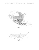
[0011]FIG. 1 is a perspective diagram of a section of an aircraft hull with a floor module installed and a floor module removed,
[0012]FIG. 2 is a view from above (in the aircraft's longitudinal direction) onto a section of the aircraft hull with floor module installed.
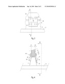
[0013]FIG. 3 is an enlarged detailed diagram of region III from FIG. 2.
[0014]FIG. 4 is a sectional view along line IV-IV from FIG. 3.
DETAILED DESCRIPTION
[0015]The invention will now be described with reference to the drawing figures, in which like reference numerals refer to like parts throughout.
[0016]As depicted in FIG. 1, the interior of an aircraft hull 10 is divided into an upper section 8 and a lower section 9. Located in lower section 9 is the cargo hold addressed here in which floor modules 20 may be fastened. These comprise floor panels 22 and roller conveyors 23 which form a walkable surface. Floor panels 22 and roller conveyors 23 are attached to cross-members 30 which are fastened using holding portions 31 to ribs 11 of an outer skin 12 of aircraft hull 10 as is specifically illustrated in FIG. 2. On the diagram, the longitudinal direction of aircraft hull 10 is identified by x, the transverse direction by y and the vertical direction by z.
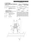
[0017]FIGS. 3 and 4 illustrate in detail an intermediate element 40 which joins holding portions 31 of cross-members 30 with aircraft hull 10.
[0018]On one hand this intermediate element 40 comprises a joining device 41 for joining intermediate element 40 with the aircraft hull or rib 11. This joining device 41 is designed to be substantially L-shaped and on one hand comprises a unilateral flange 43 which extends in line with the profile of rib 11, while on the other hand a mounting portion 48 is provided with which joining device 41 rests on rib 11 in order to dissipate loads acting perpendicularly on hull 10 or outer skin 12.
[0019]Joining device 41 is joined in one piece to a receiving device 44 which is U-shaped in cross-section and has shanks 45, 46. Holding portion 31 of cross-member 30 is insertable between these shanks in such a way that play (d1, d2) remains between holding portion 31 and shanks 45, 46. Detachable bolts 47 which pass through shanks 45, 46 and holding portion 31 are used for fastening. In this case a certain sliding displaceability of bolt 47 is guaranteed within holding portion 31 such that no stresses can arise in the x direction during movements of the hull.
[0020]The many features and advantages of the invention are apparent from the detailed specification, and, thus, it is intended by the appended claims to cover all such features and advantages of the invention which fall within the true spirit and scope of the invention. Further, since numerous modifications and variations will readily occur to those skilled in the art, it is not desired to limit the invention to the exact construction and operation illustrated and described, and, accordingly, all suitable modifications and equivalents may be resorted to that fall within the scope of the invention.
Claims:
1. Fastening device of a floor module in an aircraft hull, comprising:an
intermediate element, fastenable to the aircraft hull using a joining
device, including a receiving device for a holding portion of the floor
module such that mobility of the holding portion relative to the aircraft
hull is guaranteed in a longitudinal direction of the aircraft.
2. Fastening device according to claim 1, wherein the joining device is joinable free of play to the aircraft hull.
3. Fastening device according to claim 1, wherein the joining device is attachable to a rib of the aircraft hull.
4. Fastening device according to claim 1, wherein the joining device comprises a unilateral flange which rests on a rib of the aircraft hull.
5. Fastening device according to claim 1, wherein the receiving device comprises a fork section, between the shanks of which the holding portion is receivable with play (d1, d2).
6. Fastening device according to claim 5, further comprising at least one bolt, insertable between the shanks, that passes through the holding portion, wherein the holding portion is movable in relation to the bolt.
Description:
CROSS-REFERENCE TO RELATED APPLICATIONS
[0001]This application claims priority to foreign Patent Application No. DE 10 2009 012 428.4, filed on Mar. 10, 2009, the disclosure of which is incorporated herein by reference in its entirety.
FIELD OF THE INVENTION
[0002]The present invention relates to a fastening device of a floor module in an aircraft hull.
BACKGROUND OF THE INVENTION
[0003]Disclosed in EP 1 646 556 B1 and in EP 1 646 557 B1 is a cargo deck for accommodating cargo in the cargo hold of an aircraft, said deck being constructed of modules which may be assembled outside the aircraft hull and installed in the aircraft in a largely pre-assembled state. If the intention is to alter the aircraft's designated use, then the floor modules may be removed again and may be replaced by floor modules fitted out differently or by functional units (e.g. kitchen module or toilet module). It should be as easy as possible to carry out installation and removal.
SUMMARY OF THE INVENTION
[0004]Embodiments of the present invention advantageously provide a fastening device of a floor module in an aircraft hull which ensures easy installation and removal of a floor module.
[0005]In one embodiment, a fastening device of a floor module in an aircraft hull comprises an intermediate element which on one hand can be fastened to the aircraft hull using joining devices and which on the other comprises a receiving device for a holding portion of the floor module and which is designed in such a way that mobility of the holding portion relative to the aircraft hull is guaranteed in the aircraft's longitudinal direction.
[0006]This mobility not only ensures easier installation and removal but surprisingly it was also possible to determine that, due to this mobility in the aircraft's longitudinal direction, reduced stresses occur due to load changes on deformation of the aircraft hull.
[0007]The joining device is joined to the aircraft hull preferably free from play. This ensures that no abrasive wear can arise in the aircraft hull.
[0008]Preferably, the joining device is attached to a rib of the aircraft hull which guarantees a particularly high loading capacity. For this the joining device preferably comprises a unilateral flange which rests on the rib, as a result of which said freedom from play is ensured in a simple manner even with certain tolerances in the dimensions of the rib.
[0009]The receiving device preferably comprises a fork section between the shanks of which the holding portion is receivable with play (in the aircraft's longitudinal direction). Mobility is thus ensured at a defined point of the fastening device such that any signs of wear that arise are easily examinable. The fastening between receiving device and fork section is preferably effected by means of a bolt which passes through the holding portion and is fastened in the shanks. This guarantees easy assembly.
BRIEF DESCRIPTION OF THE DRAWINGS
[0010]An embodiment of the invention will be explained subsequently in greater detail on the basis of drawings.
[0011]FIG. 1 is a perspective diagram of a section of an aircraft hull with a floor module installed and a floor module removed,
[0012]FIG. 2 is a view from above (in the aircraft's longitudinal direction) onto a section of the aircraft hull with floor module installed.
[0013]FIG. 3 is an enlarged detailed diagram of region III from FIG. 2.
[0014]FIG. 4 is a sectional view along line IV-IV from FIG. 3.
DETAILED DESCRIPTION
[0015]The invention will now be described with reference to the drawing figures, in which like reference numerals refer to like parts throughout.
[0016]As depicted in FIG. 1, the interior of an aircraft hull 10 is divided into an upper section 8 and a lower section 9. Located in lower section 9 is the cargo hold addressed here in which floor modules 20 may be fastened. These comprise floor panels 22 and roller conveyors 23 which form a walkable surface. Floor panels 22 and roller conveyors 23 are attached to cross-members 30 which are fastened using holding portions 31 to ribs 11 of an outer skin 12 of aircraft hull 10 as is specifically illustrated in FIG. 2. On the diagram, the longitudinal direction of aircraft hull 10 is identified by x, the transverse direction by y and the vertical direction by z.
[0017]FIGS. 3 and 4 illustrate in detail an intermediate element 40 which joins holding portions 31 of cross-members 30 with aircraft hull 10.
[0018]On one hand this intermediate element 40 comprises a joining device 41 for joining intermediate element 40 with the aircraft hull or rib 11. This joining device 41 is designed to be substantially L-shaped and on one hand comprises a unilateral flange 43 which extends in line with the profile of rib 11, while on the other hand a mounting portion 48 is provided with which joining device 41 rests on rib 11 in order to dissipate loads acting perpendicularly on hull 10 or outer skin 12.
[0019]Joining device 41 is joined in one piece to a receiving device 44 which is U-shaped in cross-section and has shanks 45, 46. Holding portion 31 of cross-member 30 is insertable between these shanks in such a way that play (d1, d2) remains between holding portion 31 and shanks 45, 46. Detachable bolts 47 which pass through shanks 45, 46 and holding portion 31 are used for fastening. In this case a certain sliding displaceability of bolt 47 is guaranteed within holding portion 31 such that no stresses can arise in the x direction during movements of the hull.
[0020]The many features and advantages of the invention are apparent from the detailed specification, and, thus, it is intended by the appended claims to cover all such features and advantages of the invention which fall within the true spirit and scope of the invention. Further, since numerous modifications and variations will readily occur to those skilled in the art, it is not desired to limit the invention to the exact construction and operation illustrated and described, and, accordingly, all suitable modifications and equivalents may be resorted to that fall within the scope of the invention.
User Contributions:
Comment about this patent or add new information about this topic:
| People who visited this patent also read: | |
| Patent application number | Title |
|---|---|
| 20210020307 | SYSTEMS AND METHODS FOR PROVIDING HEALTH INFORMATION |
| 20210020306 | SYSTEMS AND METHODS FOR UPDATING FIRMWARE OF MEDICAL DEVICES WHILE MINIMIZING CLINICAL IMPACT |
| 20210020305 | SYSTEM AND METHOD FOR SCHEDULING AND MANAGING SERVICES |
| 20210020304 | SYSTEMS AND METHODS FOR GENERATING CLASSIFYING AND QUANTITATIVE ANALYSIS REPORTS OF ANEURYSMS FROM MEDICAL IMAGE DATA |
| 20210020303 | Systems and Methods for Integrating Neural Network Image Analyses Into Medical Image Viewing Applications |
Images included with this patent application:
 |  |
 |
| Similar patent applications: | |
| Date | Title |
|---|---|
| 2011-01-06 | Filtering device with integrated bypass for an air inlet |
| 2008-12-04 | Parachute-landing device for whole airplane |
| 2009-03-05 | Transmission device for a twin-rotor helicopter |
| 2010-07-01 | Method and apparatus for fast deploying and retrieving of towed bodies |
| 2012-03-15 | Passenger seat device comprising a covering unit |
| New patent applications in this class: | |
| Date | Title |
|---|---|
| 2019-05-16 | Energy dispersion plug for uav |
| 2017-08-17 | Load relief tie rod |
| 2016-07-07 | Method and device for connecting and separating two elements, with connecting plates |
| 2016-06-30 | Universal adapter plate assembly |
| 2016-06-02 | Splice assembly for joining structural components |
| New patent applications from these inventors: | |
| Date | Title |
|---|---|
| 2019-09-12 | Side guide, side guide group, cargo deck, aircraft |
| 2019-09-12 | Aircraft cargo deck and method for manufacturing a floor module |
| 2016-02-11 | Pallet adapter kit and loading unit with corresponding pallet adapter kit |
| Top Inventors for class "Aeronautics and astronautics" | |
| Rank | Inventor's name |
|---|---|
| 1 | Bernard Guering |
| 2 | The Boeing Company |
| 3 | Alain Porte |
| 4 | Olivier Cazals |
| 5 | Seiya Sakurai |