Patent application title: RETRACTABLE SYSTEM FOR AERONAUTICAL SENSORS
Inventors:
Mario Sergio Dias Ferraz (Sao Jose Dos Campos, BR)
IPC8 Class: AB64C100FI
USPC Class:
2441291
Class name: Aeronautics and astronautics aircraft structure details
Publication date: 2010-09-02
Patent application number: 20100219295
retractable optical sensor (1) composed of an
EO/IR (Electro-Optical/Infrared Remote) sensor (2) which is fastened to
an articulated structure (3) that is actuated by an actuator (4); the
structure (3) accomplishes angular movement whose turning point is
located in an end that is mounted to an articulation support (5); the
articulation support (5) is fastened to the support (6) which is fastened
to the aircraft structure (7); the actuator (4) is electrically or
hydraulically actuated and it has an end united to a support (8) which is
fastened to the aircraft structure (7); the opposite end of the actuator
(4) is articulated to the structure (3) and it promotes angular movement
of the structure (3); the EO/IR sensor (2) presents a cylindrical shape
having a spherical end; an articulated door (9) solidary to the movement
of the structure (3) is mounted close to said spherical end; the movement
of the door (9) is limited by the rods (10) for actuating the door, and
the rods (10) are also fastened to the structure (3).Claims:
1) "RETRACTABLE SYSTEM FOR AERONAUTICAL SENSORS", wherein it comprises a
retractable mechanism (1) composed of a communication/navigation
equipment (2) which is fastened to an articulated structure (3) actuated
by an actuator (4).
2) "RETRACTABLE SYSTEM FOR AERONAUTICAL SENSORS", according to claim 1, wherein the communication/navigation equipment (2) is defined by an infrared optical sensor.
3) "RETRACTABLE SYSTEM FOR AERONAUTICAL SENSORS", according to claim 1, wherein the structure (3) accomplishes an angular movement whose turning point is located in an end that is mounted to an articulation support (5).
4) "RETRACTABLE SYSTEM FOR AERONAUTICAL SENSORS", according to claim 1, wherein the articulation support (5) is fastened to the support (6) which is fastened to the aircraft structure (7).
5) "RETRACTABLE SYSTEM FOR AERONAUTICAL SENSORS", according to claim 1, wherein the actuator (4) has an end united to a support (8) which is fastened to the aircraft structure (7); the opposite end of the actuator (4) is articulated to the structure (3).
6) "RETRACTABLE SYSTEM FOR AERONAUTICAL SENSORS", according to claim 1, wherein the actuator (4) is electrically or hydraulically actuated and it promotes angular movement of the structure (3).
7) "RETRACTABLE SYSTEM FOR AERONAUTICAL SENSORS", according to claim 1, wherein the optical sensor (2) presents a cylindrical shape having a spherical end.
8) "RETRACTABLE SYSTEM FOR AERONAUTICAL SENSORS", according to claim 1, wherein an articulated door (9) solidary to the movement of the structure (3) is mounted close to the internal wall of the fairing of the protection compartment.
9) "RETRACTABLE SYSTEM FOR AERONAUTICAL SENSORS", according to claim 1, wherein the articulation points of the hinges with the points of the structure (3) are interlinked by a pair of rods (10).
10) "RETRACTABLE SYSTEM FOR AERONAUTICAL SENSORS", according to claim 1, wherein the door (9) is defined by a substantially curved sheet fitting in practically half of the contour of the circular surface of said sensor (2).
11) "RETRACTABLE SYSTEM FOR AERONAUTICAL SENSORS", according to claim 1, wherein the communication/navigation equipment (2) is a radar and/or antenna.Description:
[0001]The present invention patent discloses a constructive form for a
retractable system applied in aircraft, said system having a mechanism
contained in a protection compartment allowing retraction or exposition
of a communication/navigation equipment, such as an optical-electronic
sensor. The elucidated system presents a constructive disposition that
makes possible to guarantee the integrity of the equipment, spending less
space for accommodation, low influence in the air flow passing by the
aircraft fuselage and, in consequence, low vibration of the equipment.
DESCRIPTION OF STATE OF ART
[0002]The aviation, either civilian or military, uses several electronic systems, which are fundamental for communication activities, navigation and warning (surveillance), such as sensors, antennas and radar. The optical sensors allow the pilot identify specifically geographical accidents in low visibility environments. The electronic systems, depending on the purpose and dimensions of the equipments, are allocated in the aircraft belly, disposed externally or in compartments having a specific fairing, characterizing a protuberance on the smooth lines of the aircraft.
[0003]The inconveniences of such protuberances reside in the fact of an increase in the aerodynamic drag, which influences the consumption of fuel, range and speed limit of the aircraft directly, and also promotes turbulence. Further, generally speaking, the properly said sensors present a spherical shape in whose surface is located one or more lenses with a circular format in plan. Once such sensors are exposed to airflow, they become susceptible to vibrations due detachment of aerodynamic vortexes. It is also known, that useful life of the sensors is related to the intensity of the vibrations which are proportional to dynamic pressure and exposure of the sensors to the airflow.
[0004]Due the cost of such equipments and strategic importance in reconnaissance missions, the installation in aircraft is usually made in a way what the equipment is retractile, making possible its exposure when necessary and retraction when it is not in use.
[0005]Among the different types of known retractable systems, the most common are those that execute vertical movement as taught by U.S. Pat. No. 3,982,250, U.S. Pat No. 3,656,164, U.S. Pat. No. 4,593,288, U.S. Pat. No. 5,969,686, U.S. Pat. No. 5,918,834. However, such a vertical movement implicates in interfaces with the pressurized area of the aircraft or in generation of great protuberances on the exterior side of the fuselage and, consequently, the inconveniences above mentioned.
[0006]In other exposition/retraction pantographic systems also known, the operation kinematics is seen as a complex procedure mainly due to interaction with the articulated doors, which are defined by heavy mechanisms having big physical dimensions responsible for maintaining the compartment closed. This is because their surfaces generate disturbances in the air flow when they are extended during the flight, so that the whole assemblage becomes subject to strong vibrations which cause, along the time, mechanical wearing for the parts composing the system and damage to the sensors.
[0007]It is noticed that the previous state of art is replete of inconveniences that induce to high costs of operation and maintenance. Thus, the present invention discloses a new technique that suppresses such inconveniences, as well as it provides a smooth curvilinear surface that reduces turbulence and drag.
SUMMARY OF THE INVENTION
[0008]The objective of the present invention is to present a retractable system for aeronautical sensors which is capable to guarantee physical integrity of the equipment.
[0009]Another objective of the present invention is to present a retractable system for aeronautical sensors that makes possible exposition and retraction of the electronic equipment starting from a short angular movement.
[0010]Another objective of the present invention is to present a retractable system for aeronautical sensors that uses just a single door built in a fairing of the aircraft.
[0011]Another objective of the present invention is to present a retractable system for aeronautical sensors which doesn't require exaggerating protuberances on the aircraft fuselage or wing, thus allowing a minimal space for accommodation inside the aircraft.
BRIEF DESCRIPTION OF DRAWINGS
[0012]The present invention will be briefly described based in an embodiment example represented by the drawings. The figures show:
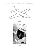
[0013]FIG. 1--a schematic perspective view of an aircraft having a sensor according to previous state of art;
[0014]FIG. 1b--a schematic perspective view of an infrared optical sensor in an exposed position.
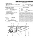
[0015]FIG. 2--a side view of the retractable system for aeronautical sensors, in a retracted position;
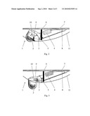
[0016]FIG. 3--a side view of the retractable system for aeronautical sensors, in a position of exposition of the sensor.
[0017]FIG. 4--a second side view of the retractable system for aeronautical sensors, in a position of retraction of the sensor.
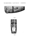
[0018]FIG. 5--a lower view of the retractable system for aeronautical sensors, in a position of exposition of the sensor.
DETAILED DESCRIPTION OF THE INVENTION
[0019]The present invention solves the inconveniences of the previous state of art, through a sensor disposed in an articulated structure, which is movable through an actuator. There is a door, solidary to the sensor, fitted to the channel through a place where the sensor is exposed, so that the movement of the door and of the sensor is reduced, minimizing the adjustment and loosen spaces problems.
[0020]FIG. 1 presents a schematic perspective view of an aircraft having a sensor, according to previous state of art, wherein it is noticed an area with bulbous shape located on the lower portion of the fuselage.
[0021]In FIG. 1b it is illustrated in details the sensor in exposed position according to previous state of art. In this representation, the exposition and retraction system doesn't have means that can impede the passage of air to the interior of the fuselage.
[0022]In the FIG. 2 it is exhibited the duramen of the present invention, the retractable system 1 being composed by an infrared optical sensor 2 or simply EO/IR (Electro-Optical/Infrared Remote) which is assembled to a structure 3 having a substantially trapezoidal profile which is articulated according to the action of an actuator device 4.
[0023]The structure 3 accomplishes angular movement whose turning point is located in an end mounted respectively on a bearing or articulation support 5. The articulation support 5 is fastened to the support 6 that is perpendicularly fastened in the face of the aircraft structure 7.
[0024]The actuator 4 can be electrically or hydraulically actuated and it presents one of its ends united to a support 8 that is fastened to the aircraft structure 7. The opposite end of the actuator 4, specifically the extremity of the piston, is articulated in relation to the structure 3 and it promotes the angular movement of said structure.
[0025]An articulated door 9 solidary to the movement of the structure 3 is mounted close to the internal wall of the fairing that protects the system. The movement of said door is limited by a pair of rods 10 that interconnect the articulation points of the hinges with the points of the structure 3.
[0026]The door 9 is defined by a substantially curved sheet fitting in practically half of the contour of the circular surface of said sensor 2.
[0027]From the condition showed in FIG. 2 to the condition presented in FIG. 3, basically, the kinematics of exposition of the retractable optical sensor is comprised by the action of the actuator 4, which upon pushing the piston promotes a simultaneous angular movement of the structure 3, door 9 and EO/IR 2. Such a movement makes the EO/IR sensor 2 to be positioned beyond the surface of the fairing 11, giving it operation conditions. In this condition, the EO/IR sensor 2 fills in integrally an opening in the fairing 11, thus impeding that the air flow generates improper vibrations to the other components comprising the retractable system 1.
[0028]The retraction of the mechanism, according to FIG. 2, is provided again by the actuator 4, which when pulling the piston rotates the structure 3, door 9 and EO/IR sensor 2. In this condition, the door 9 is responsible for obstructing the existent openings between the EO/IR sensor 2 and the opening of the fairing 11.
[0029]From the description above it is evident that the advantage of the present invention resides in the fact of providing a retractable system 1 capable of exposing and retracting the infrared optical sensor without the need of actuator devices and doors assembly demanding to be conditioned in voluminous protection fairings.
[0030]A small portion of the semi-spherical or ogival end of the sensor 2 is maintained projected outside of the fairing. However, the influence of such protuberance in the generation of drag is minimal.
[0031]These advantages are of relevant importance from the economical and strategic point of view, because besides increasing the useful life of the infrared optical sensor 2 and of the whole equipment, they also allow a best performance of the aircraft during the execution of its missions.
[0032]It was described an example of favourite materialization of the invention, and it should be understood that the scope of the present invention includes other possible variations, such as employment of several types of radar and/or antennas, and it is only limited by the tenor of the attached claims, comprising its possible equivalents.
Claims:
1) "RETRACTABLE SYSTEM FOR AERONAUTICAL SENSORS", wherein it comprises a
retractable mechanism (1) composed of a communication/navigation
equipment (2) which is fastened to an articulated structure (3) actuated
by an actuator (4).
2) "RETRACTABLE SYSTEM FOR AERONAUTICAL SENSORS", according to claim 1, wherein the communication/navigation equipment (2) is defined by an infrared optical sensor.
3) "RETRACTABLE SYSTEM FOR AERONAUTICAL SENSORS", according to claim 1, wherein the structure (3) accomplishes an angular movement whose turning point is located in an end that is mounted to an articulation support (5).
4) "RETRACTABLE SYSTEM FOR AERONAUTICAL SENSORS", according to claim 1, wherein the articulation support (5) is fastened to the support (6) which is fastened to the aircraft structure (7).
5) "RETRACTABLE SYSTEM FOR AERONAUTICAL SENSORS", according to claim 1, wherein the actuator (4) has an end united to a support (8) which is fastened to the aircraft structure (7); the opposite end of the actuator (4) is articulated to the structure (3).
6) "RETRACTABLE SYSTEM FOR AERONAUTICAL SENSORS", according to claim 1, wherein the actuator (4) is electrically or hydraulically actuated and it promotes angular movement of the structure (3).
7) "RETRACTABLE SYSTEM FOR AERONAUTICAL SENSORS", according to claim 1, wherein the optical sensor (2) presents a cylindrical shape having a spherical end.
8) "RETRACTABLE SYSTEM FOR AERONAUTICAL SENSORS", according to claim 1, wherein an articulated door (9) solidary to the movement of the structure (3) is mounted close to the internal wall of the fairing of the protection compartment.
9) "RETRACTABLE SYSTEM FOR AERONAUTICAL SENSORS", according to claim 1, wherein the articulation points of the hinges with the points of the structure (3) are interlinked by a pair of rods (10).
10) "RETRACTABLE SYSTEM FOR AERONAUTICAL SENSORS", according to claim 1, wherein the door (9) is defined by a substantially curved sheet fitting in practically half of the contour of the circular surface of said sensor (2).
11) "RETRACTABLE SYSTEM FOR AERONAUTICAL SENSORS", according to claim 1, wherein the communication/navigation equipment (2) is a radar and/or antenna.
Description:
[0001]The present invention patent discloses a constructive form for a
retractable system applied in aircraft, said system having a mechanism
contained in a protection compartment allowing retraction or exposition
of a communication/navigation equipment, such as an optical-electronic
sensor. The elucidated system presents a constructive disposition that
makes possible to guarantee the integrity of the equipment, spending less
space for accommodation, low influence in the air flow passing by the
aircraft fuselage and, in consequence, low vibration of the equipment.
DESCRIPTION OF STATE OF ART
[0002]The aviation, either civilian or military, uses several electronic systems, which are fundamental for communication activities, navigation and warning (surveillance), such as sensors, antennas and radar. The optical sensors allow the pilot identify specifically geographical accidents in low visibility environments. The electronic systems, depending on the purpose and dimensions of the equipments, are allocated in the aircraft belly, disposed externally or in compartments having a specific fairing, characterizing a protuberance on the smooth lines of the aircraft.
[0003]The inconveniences of such protuberances reside in the fact of an increase in the aerodynamic drag, which influences the consumption of fuel, range and speed limit of the aircraft directly, and also promotes turbulence. Further, generally speaking, the properly said sensors present a spherical shape in whose surface is located one or more lenses with a circular format in plan. Once such sensors are exposed to airflow, they become susceptible to vibrations due detachment of aerodynamic vortexes. It is also known, that useful life of the sensors is related to the intensity of the vibrations which are proportional to dynamic pressure and exposure of the sensors to the airflow.
[0004]Due the cost of such equipments and strategic importance in reconnaissance missions, the installation in aircraft is usually made in a way what the equipment is retractile, making possible its exposure when necessary and retraction when it is not in use.
[0005]Among the different types of known retractable systems, the most common are those that execute vertical movement as taught by U.S. Pat. No. 3,982,250, U.S. Pat No. 3,656,164, U.S. Pat. No. 4,593,288, U.S. Pat. No. 5,969,686, U.S. Pat. No. 5,918,834. However, such a vertical movement implicates in interfaces with the pressurized area of the aircraft or in generation of great protuberances on the exterior side of the fuselage and, consequently, the inconveniences above mentioned.
[0006]In other exposition/retraction pantographic systems also known, the operation kinematics is seen as a complex procedure mainly due to interaction with the articulated doors, which are defined by heavy mechanisms having big physical dimensions responsible for maintaining the compartment closed. This is because their surfaces generate disturbances in the air flow when they are extended during the flight, so that the whole assemblage becomes subject to strong vibrations which cause, along the time, mechanical wearing for the parts composing the system and damage to the sensors.
[0007]It is noticed that the previous state of art is replete of inconveniences that induce to high costs of operation and maintenance. Thus, the present invention discloses a new technique that suppresses such inconveniences, as well as it provides a smooth curvilinear surface that reduces turbulence and drag.
SUMMARY OF THE INVENTION
[0008]The objective of the present invention is to present a retractable system for aeronautical sensors which is capable to guarantee physical integrity of the equipment.
[0009]Another objective of the present invention is to present a retractable system for aeronautical sensors that makes possible exposition and retraction of the electronic equipment starting from a short angular movement.
[0010]Another objective of the present invention is to present a retractable system for aeronautical sensors that uses just a single door built in a fairing of the aircraft.
[0011]Another objective of the present invention is to present a retractable system for aeronautical sensors which doesn't require exaggerating protuberances on the aircraft fuselage or wing, thus allowing a minimal space for accommodation inside the aircraft.
BRIEF DESCRIPTION OF DRAWINGS
[0012]The present invention will be briefly described based in an embodiment example represented by the drawings. The figures show:
[0013]FIG. 1--a schematic perspective view of an aircraft having a sensor according to previous state of art;
[0014]FIG. 1b--a schematic perspective view of an infrared optical sensor in an exposed position.
[0015]FIG. 2--a side view of the retractable system for aeronautical sensors, in a retracted position;
[0016]FIG. 3--a side view of the retractable system for aeronautical sensors, in a position of exposition of the sensor.
[0017]FIG. 4--a second side view of the retractable system for aeronautical sensors, in a position of retraction of the sensor.
[0018]FIG. 5--a lower view of the retractable system for aeronautical sensors, in a position of exposition of the sensor.
DETAILED DESCRIPTION OF THE INVENTION
[0019]The present invention solves the inconveniences of the previous state of art, through a sensor disposed in an articulated structure, which is movable through an actuator. There is a door, solidary to the sensor, fitted to the channel through a place where the sensor is exposed, so that the movement of the door and of the sensor is reduced, minimizing the adjustment and loosen spaces problems.
[0020]FIG. 1 presents a schematic perspective view of an aircraft having a sensor, according to previous state of art, wherein it is noticed an area with bulbous shape located on the lower portion of the fuselage.
[0021]In FIG. 1b it is illustrated in details the sensor in exposed position according to previous state of art. In this representation, the exposition and retraction system doesn't have means that can impede the passage of air to the interior of the fuselage.
[0022]In the FIG. 2 it is exhibited the duramen of the present invention, the retractable system 1 being composed by an infrared optical sensor 2 or simply EO/IR (Electro-Optical/Infrared Remote) which is assembled to a structure 3 having a substantially trapezoidal profile which is articulated according to the action of an actuator device 4.
[0023]The structure 3 accomplishes angular movement whose turning point is located in an end mounted respectively on a bearing or articulation support 5. The articulation support 5 is fastened to the support 6 that is perpendicularly fastened in the face of the aircraft structure 7.
[0024]The actuator 4 can be electrically or hydraulically actuated and it presents one of its ends united to a support 8 that is fastened to the aircraft structure 7. The opposite end of the actuator 4, specifically the extremity of the piston, is articulated in relation to the structure 3 and it promotes the angular movement of said structure.
[0025]An articulated door 9 solidary to the movement of the structure 3 is mounted close to the internal wall of the fairing that protects the system. The movement of said door is limited by a pair of rods 10 that interconnect the articulation points of the hinges with the points of the structure 3.
[0026]The door 9 is defined by a substantially curved sheet fitting in practically half of the contour of the circular surface of said sensor 2.
[0027]From the condition showed in FIG. 2 to the condition presented in FIG. 3, basically, the kinematics of exposition of the retractable optical sensor is comprised by the action of the actuator 4, which upon pushing the piston promotes a simultaneous angular movement of the structure 3, door 9 and EO/IR 2. Such a movement makes the EO/IR sensor 2 to be positioned beyond the surface of the fairing 11, giving it operation conditions. In this condition, the EO/IR sensor 2 fills in integrally an opening in the fairing 11, thus impeding that the air flow generates improper vibrations to the other components comprising the retractable system 1.
[0028]The retraction of the mechanism, according to FIG. 2, is provided again by the actuator 4, which when pulling the piston rotates the structure 3, door 9 and EO/IR sensor 2. In this condition, the door 9 is responsible for obstructing the existent openings between the EO/IR sensor 2 and the opening of the fairing 11.
[0029]From the description above it is evident that the advantage of the present invention resides in the fact of providing a retractable system 1 capable of exposing and retracting the infrared optical sensor without the need of actuator devices and doors assembly demanding to be conditioned in voluminous protection fairings.
[0030]A small portion of the semi-spherical or ogival end of the sensor 2 is maintained projected outside of the fairing. However, the influence of such protuberance in the generation of drag is minimal.
[0031]These advantages are of relevant importance from the economical and strategic point of view, because besides increasing the useful life of the infrared optical sensor 2 and of the whole equipment, they also allow a best performance of the aircraft during the execution of its missions.
[0032]It was described an example of favourite materialization of the invention, and it should be understood that the scope of the present invention includes other possible variations, such as employment of several types of radar and/or antennas, and it is only limited by the tenor of the attached claims, comprising its possible equivalents.
User Contributions:
Comment about this patent or add new information about this topic:
| People who visited this patent also read: | |
| Patent application number | Title |
|---|---|
| 20160144660 | CYCLE WHEEL RIM AND MANUFACTURING METHOD THEREFOR |
| 20160144659 | VEHICLE WHEEL HUBCAP WITH VENT |
| 20160144658 | COMPOSITE FIBER BICYCLE WHEELS |
| 20160144657 | DECORATIVE EGG SYSTEM AND METHOD |
| 20160144656 | METHOD FOR AFFIXING DECORATIVE OBJECT AND DECORATIVE OBJECT |
Images included with this patent application:
 |  |
 |  |
| Similar patent applications: | |
| Date | Title |
|---|---|
| 2009-07-23 | Constant-velocity drive system for gimbaled rotor hubs |
| 2012-07-12 | Pre-installed adaptable supply network for aeroplanes |
| 2012-11-15 | Strain reduction on a balloon system in extreme weather conditions |
| 2013-01-10 | Air to air refueling system with an autonomous electrical system |
| 2013-01-10 | Retractable vortex generator for reducing stall speed |
| New patent applications from these inventors: | |
| Date | Title |
|---|---|
| 2011-07-21 | Landing gear mechanism for aircraft |
| Top Inventors for class "Aeronautics and astronautics" | |
| Rank | Inventor's name |
|---|---|
| 1 | Bernard Guering |
| 2 | The Boeing Company |
| 3 | Alain Porte |
| 4 | Olivier Cazals |
| 5 | Seiya Sakurai |