Patent application title: SEAMLESS RESISTIVE GARMENTS
Inventors:
Marino Cavaion (Montebelluna (treviso), IT)
Gabriele Pini (Farra Di Soligo (treviso), IT)
IPC8 Class: AD04B124FI
USPC Class:
66171
Class name: Fabrics or articles articles garments
Publication date: 2010-08-19
Patent application number: 20100206012
Inventors list |
Agents list |
Assignees list |
List by place |
Classification tree browser |
Top 100 Inventors |
Top 100 Agents |
Top 100 Assignees |
Usenet FAQ Index |
Documents |
Other FAQs |
Patent application title: SEAMLESS RESISTIVE GARMENTS
Inventors:
Marino Cavaion
Gabriele Pini
Agents:
MCGLEW & TUTTLE, PC
Assignees:
Origin: SCARBOROUGH, NY US
IPC8 Class: AD04B124FI
USPC Class:
Publication date: 08/19/2010
Patent application number: 20100206012
Abstract:
Resistive garments featuring a special knit, realized by circular knitting
machines, fitted in some areas with an electrical circuit realised by
direct knitting of conductive yarn in combination with a base of
non-resistive yarn. The electrical circuit of this resistive garment is
made up by three different knitting structures for "held or excluded
stitches" with no cutting or stitching, in direct connection, without
interruptions of any type. An electronic circuit allows the control of
energy flowing in to the different heating zones of the electric circuit.Claims:
1. A resistive garment in tubular knit constructed on circular knitting
machines, comprising:an electrical circuit in at least one part of the
garment, said electrical circuit being produced by direct knitting of a
conductive yarn together with at least one non-conductive base yarn, and
formed of at least three portions of different structures of knit
constructed with held or excluded stitches, with no cutting or stitching,
in direct connection, without any interruption, said electrical circuit
comprising a first section with a structure of horizontal knit in which
the knit of the base yarn is alternated in a vertical direction with
conductive yarn.
2. (canceled)
3. (canceled)
4. A resistive garment in tubular knit in accordance with claim 1, wherein the electrical circuit is made up of a second section with a structure of vertical knitting in which the conductive yarn is knitted, while the base yarn is excluded from the knit and cut.
5. A resistive garment in tubular knit in accordance with claim 4, wherein the electrical circuit is made up of a third section with a knitted structure comprising a heat dissipating knit including alternated conductive yarns, while in the other zones of the circuit the conductive yarns are present in every rank.
6. A resistive garment in tubular knit in accordance with claim 1, wherein the garment is seamless along the sides and which can take the shape of: T-shirts, shirts, cardigans, sweaters, underpants, boxer shorts, shorts, trousers, knee-pads, elbow-pads, wrist bands, ankle bands, socks, hosiery, tights, gloves, children's wear, garments for animals, wrappings for plants, covers for instruments, jackets, overalls and all other garments, or parts thereof, for the heating of the human body, of animals, of plants, the covering of instruments and tools, the protection of electronic parts and any and all possible uses of induced heating.
7. A resistive garment in tubular knit in accordance with claim 1, wherein the conductive yarn is knitted only along a horizontal plane using sequenced purl stitching.
8. A resistive garment in tubular knit in accordance with claim 1, wherein the electrical circuit is controlled by an electronic circuit set up to activate the heating areas selectively, manage a function of said heating areas and regulate the amount of current supplied.
9. A resistive garment in tubular knit as in accordance with claim 8, wherein the electrical circuit is supplied from a main supply or by battery.
10. A resistive garment in tubular knit in accordance with claim 9, wherein the batteries are rechargeable, also using photovoltaic panels.
11. A resistive garment in tubular knit in accordance with claim 8, wherein the electronic circuit is controlled by a switch or remote control.
12. A resistive garment in tubular knit in accordance with claim 9, wherein the electronic circuit is controlled by a switch or remote control.
Description:
[0001]Currently there are no resistive garments on, the market featuring,
a special knit of conductive yarn always and in any case combined with a
base of non-resistive yarn:
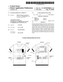
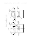
[0002]The knit of the horizontal resistive zone (FIG. 1/1-zone A) which makes up most of the electrical conduction, utilises the knit of the base yarn vertically alternated with the conductive yarn (FIG.2/2-zone A).
[0003]The knit of the vertical conductive zone (FIG.1/1-zone B) is constructed so that the conductive yarn is knitted and the base yarn, excluded during the knitting process, is cut (FIG. 2/2-zone B).
[0004]The knit of the zone where the heating takes place (FIG. 1/1 zone-C) is characterised by alternated conductive yarns, while in other zones of conduction the conductive yarn is present in every rank (FIG. 2/2-zone C).
[0005]The garments, as per the invention, are fitted with an electrical circuit with conductive yarn for thermal induction supplied by batteries which enable part of the body to be warmed. The fabric of these garments is very thin, very light, close-fitting (with omni-directional elasticity) almost like a second skin, and pleasing to the touch. This renders it ideal for the production of stockings, tights, underwear for newborn babies, T-shirts, underwear, socks, gloves and many other types of garment which are produced using an extremely low denier such as 20/25/30 Dtex and which are made using a knit with highly reduced diameters which corresponds perfectly to the dimensions of parts of the body and also to the circumference of the human body itself so that, in the case of a T-shirt or pair of briefs or similar, there is no stitching on the sides.
[0006]The tubular knit is made of a conductive yarn which works only in the horizontal plane by means of a sequence of purl stitches (FIG.2/2-zone D), therefore the tube has no stitching which could negate or limit the electrical conductivity of the circuit.
[0007]The invention consists of the production of garments, as described above, which use an integrated electrical circuit (FIG. 1/1) with a special knit of conductive yarn which are always used together with a base of different yarns;
to explain better: the fabric is made with conductive yarns which form an electrical circuit in the structure of the garment capable of heating parts of the body. The electricity supply can be provided from the mains circuit using a plug or from batteries; the latter can be recharged using a suitable battery charger or photovoltaic panels.
[0008]The heat produced can be adjusted as necessary; an electronic circuit will enable different parts of the body to be heated, and can be selected by using a radio-control device. The working current is significantly lower than that which can be felt by the wearer and therefore constitutes no danger for the user.
[0009]The invention is unique because of the use of an original knit of conductive yarns which are always used together with different, non-conductive base yarn.
[0010]The electrical circuit is an integral part of the knitted fabric and, is made up of different structures for held or excluded stitches with no cutting or stitching, in direct connection, without interruption of any type:
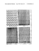
A) Zone A, ribbed, horizontal (FIG. 1/1-A): the knit of the base yarn is alternated in a vertical direction with the conductive yarn (FIG.2/2-zone A).B) Zone B, which is totally covered by conductive yarn, vertical (FIG. 1/1-B): the conductive yarn is knitted and the base yarn, excluded in the knit, is cut (FIG. 2/2-zone B).C) Zone C with alternated conductive yarns (FIG. 1/1-C): this is the zone where the resistance is greatest and is therefore where the heating takes place (conversion of electrical energy into dissipated heat energy). The conductive yarn is only knitted into alternate ranks, for example 1 rank in every 4, while in the other zones the conductive yarn is present in every rank (FIG. 2/2-zone C).
[0011]The heating textile fabric works on the base of Joule's effect. That circuit consists of many conductor yarns matched with other non-conductor yarns. The conductor yarns are properly connected in series or parallel, depending on the equivalent section where the current flows, those yarns have function of conductors or resistors. On the base of Joule's principle, an electric current flowing into a conductor material produces thermal energy and the relation between those values depends on the material resistance. The resistance of material depends on a physical characteristic of the material (resistivity).
[0012]As far as the application is concerned, the conductor threads are manufactured by plating a superficial silver layer on a basic polyamide tread. Silver is a metal that has the property to be one of best conductors of heat and electricity.
[0013]It possible to create some heating zones by arranging a certain number of conductor threads and by connecting them in parallel by means of a proper short circuit at their ends. Each of those threads is similar to a resistor. The number of resistors working in parallel may change depending on the required temperature and the heating surface. In order to carry the current to the proper heating zones without wasting energy, a low-resistance connection it's required. This is possible by applying a higher number of conductor threads, very close one to another, forming a low resistance path between the heating zones and the supply terminals. The section of this conductor layer depends of the current flowing in it The supply terminals are by means of two metallic clip-buttons fixed on the textile. Those clip-buttons can be plugged to the terminals of an external device which supply the circuit.
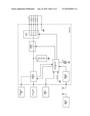
[0014]The supply source consists of one or more batteries, properly connected, which capacity is chosen in function of the required heating time. An electronic circuit allows the control of energy flowing into the different heating zones (FIG.3/3-1).
[0015]The selection of the heating zone is allowed by applying a switching device. This device consists of a microprocessor-based electronic circuit that manages power components like MosFets or Transistors (FIG. 3/3-3).
[0016]The current value is modified by an electronic switch (FIG.3/3-4) which could be the same component used for switching the external circuit (FIG. 3/3-2). In the block diagram the functions of selection and control are divided but practically those functions could be done by the same electronic component. The value of electric energy supplied to resistors (FIG. 3/3-1) could be changed by modifying the conduction-time of the switching device (PWM principle). The timing is managed by the microprocessor (FIG. 3/3-3).
[0017]The selection of which resistance should be supplied and the current value is chosen by the operator (FIG. 3/3-3).
[0018]The switching command could be by means of a push-button (FIG.3/3-5) or by means of a remote control (FIG. 3/3-7). If the command is given by the push-button, the operation (increase/decrease temperature-switch heating zone) is selected by a proper command sequence depending, for instance, from the pushing time.
[0019]The electronic controller of the supply source checks also the status of rechargeable batteries (FIG. 3/3-8) and manages their charging process. The charge level of batteries is showed by a visual code, like, for instance, the blinking frequency of a LED (FIG. 3/3-10).
[0020]The recharge of batteries (FIG. 3/3-8) could be done by using two different sources:
an external supply plugged to mains (FIG. 3/3-11) that, by means of a proper galvanic isolation, assures the recharge of battery and the safety of operator;a photovoltaic panel (FIG. 3/3-12) that assures the recharge of batteries when mains is not available.
User Contributions:
comments("1"); ?> comment_form("1"); ?>Inventors list |
Agents list |
Assignees list |
List by place |
Classification tree browser |
Top 100 Inventors |
Top 100 Agents |
Top 100 Assignees |
Usenet FAQ Index |
Documents |
Other FAQs |
User Contributions:
Comment about this patent or add new information about this topic:
| People who visited this patent also read: | |
| Patent application number | Title |
|---|---|
| 20210383629 | ACCESS CONTROL SYSTEM AND METHOD FOR OPERATING AN ACCESS CONTROL SYSTEM |
| 20210383628 | SPACE MANAGEMENT DEVICE |
| 20210383627 | INFORMATION PROCESSING APPARATUS, INFORMATION PROCESSING METHOD, STORAGE MEDIUM, AND INFORMATION PROCESSING SYSTEM |
| 20210383626 | SYSTEM AND METHOD OF IDENTIFYING AND VERIFYING A VALID ENTRY OF AN APPLICATION USER INTO A VENUE USING CONTACLESS CREDENTIAL VERIFICATION |
| 20210383625 | Access Control Via Selective Direct and Indirect Wireless Communications |
Images included with this patent application:
 |  |
 |  |
| Similar patent applications: | |
| Date | Title |
|---|---|
| 2011-01-06 | Stain masking cut resistant gloves and processes for making same |
| 2010-11-11 | Staple fiber yarn, method for producing a textile article, and textile article |
| 2009-01-01 | Channeled moisture management sock |
| 2011-03-03 | Method of forming garments having seamless edge bands |
| 2008-10-09 | Yarn processing system and yarn feeding device |
| New patent applications in this class: | |
| Date | Title |
|---|---|
| 2016-12-29 | Method for producing an article of clothing and an article of clothing |
| 2016-03-17 | Compression fabrics with tailored comfort |
| 2016-01-21 | Fabric system |
| 2015-05-07 | Fully spandex weft-knitted cloth and production method thereof and lingerie lining |
| 2015-03-26 | Composite waterproof breathable elastic hats and methodology and dies used to manufacture such hats |
| Top Inventors for class "Textiles: knitting" | |
| Rank | Inventor's name |
|---|---|
| 1 | Tiberio Lonati |
| 2 | Fausto Lonati |
| 3 | Ettore Lonati |
| 4 | Uwe Stingel |
| 5 | Ettore Lonati |