Patent application title: Topside Beam
Inventors:
T.h. Huang (Qingdao, CN)
Robert Wang (Qingdao, CN)
Ryan Xu (Qingdao, CN)
Jack Zhang (Qingdao, CN)
Gary Liu (Qingdao, CN)
Assignees:
CHINA INTERNATIONAL MARINE CONTAINERS (GROUP) LTD.
QINGDAO CIMC REEFER TRAILER CO., LTD.
Qingdao CIMC Reefer Container Manufacture Co., Ltd
Qingdao CIMC Special Reefer Co., Ltd.
IPC8 Class: AE04C302FI
USPC Class:
52846
Class name: Elongated rigid structure (e.g., beam, column, girder, shaft, reinforcing bar or rod, etc.) made up of longitudinally arranged strip-like sections having an angular component (e.g., l, t, z cross section, etc.)
Publication date: 2010-08-19
Patent application number: 20100205902
topside beam. The topside beam comprises: an
upper topside beam that is comprised of an upper web beam (10), an upper
left wing beam (12) and upper right wing beam (11), wherein the section
of the upper web beam (10) has a shape of an inverted "L"; the upper left
wing beam (12) and the upper right wing beam (11) are oppositely
connected to the two sides adjacent to the lower end of the upper web
beam (10) respectively; the upper left wing beam (12) opposite to the
upper web beam (10) inclines downwardly; and the upper right wing beam
(11) is located at 90° with the upper web beam. And a lower
topside beam that is comprised of a lower web beam (20) and a lower right
wing beam (21), wherein the lower right wing beam (21) is connected to
the right side adjacent to the upper end of the lower web beam (20); and
the lower right wing beam (21) opposite to the lower web beam (20)
inclines upwardly and is parallel to the upper left wing beam (12). And
besides, the upper left wing beam (12) and the lower right wing beam (21)
are tightly connected by a connecting member.Claims:
1. A topside beam comprising:an upper topside beam comprised of an upper
web beam, an upper left wing beam and an upper right wing beam, wherein a
section of the upper web beam has a shape of an inverted "L"; the upper
left wing beam and the upper right wing beam are oppositely connected to
both sides of the upper web beam, respectively, at positions adjacent to
a lower end of the upper web beam; andthe upper left wing beam inclines
downwardly in respect to the upper web beam, the upper right wing beam
and the upper web beam from an angel of 90.degree.;a lower topside beam
comprised of a lower web beam and a lower right wing beam, wherein the
lower right wing beam is connected to a right side of the lower web beam
at a position adjacent to an upper end of the lower web beam, and the
lower right wing beam inclines upwardly in respect to the lower web beam
and is parallel to the upper left wing beam; andthe upper left wing beam
and the lower right wing beam are tightly connected by a connecting
member.
2. The topside beam according to claim 1, wherein the upper left wing beam inclines downwardly 120.degree. in respect to the upper web beam.
3. The topside beam according to claim 1, wherein one end of an exterior decorative plate is riveted to outside of a top end of the upper web beam, and the other end of the exterior decorative plate is inserted to an upper end of the lower web beam; and a decorative lace is adhered between the exterior decorative plate and the upper end of the lower web beam.
4. The topside beam according to claim 3, wherein the exterior decorative plate is made of a mirror finished stainless steel, and the decorative lace is made of a color PVC.Description:
FIELD OF THE INVENTION
[0001]The present invention relates to a connection structure of a roof plate and a side plate in a container, and more particularly a topside beam of the container.
BACKGROUND OF THE INVENTION
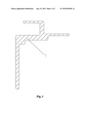
[0002]FIG. 1 is a sectional view of a topside beam in the prior art. As shown in FIG. 1, because the topside beam 1 in the prior art has an integrated structure, it cannot be transported separately from a roof plate and a side plate of the container, as a result, it is not easy to transport the containers in batches.
SUMMARY OF THE INVENTION
[0003]According to the above problem, an object of the invention is to provide a topside beam for facilitating transportation.
[0004]For solving the above problem, the invention is implemented by the following technical solutions.
[0005]A topside beam comprises an upper topside beam and a lower topside beam, wherein the upper topside beam is comprised of an upper web beam, an upper left wing beam and an upper right wing beam; the section of the upper web beam has a shape of an inverted "L"; the upper left wing beam and the upper right wing beam are connected oppositely to both sides of the upper web beam, respectively, at positions adjacent to a lower end of the upper web beam; and the upper left wing beam inclines downwardly in respect to the upper web beam, the upper right wing beam and the upper web beam form an angle of 90°. Moreover, the lower topside beam is comprised of a lower web beam and a lower right wing beam, wherein the lower right wing beam is connected to a right side of the lower web beam at a location adjacent to an upper end of the lower web beam; the lower right wing beam inclines upwardly in respect to the lower web beam and is parallel to the upper left wing beam. Additionally, the upper topside beam and the lower topside beam are tightly connected by a connecting member.
[0006]Furthermore, the upper left wing beam opposite to the upper web beam inclines downwardly 120°.
[0007]Additionally, one end of an exterior decorative is riveted to outside of a top end of the upper web beam, the other end is inserted into the upper end of the lower web beam, and a trimming is adhered between the exterior decorative and the upper end of the lower web beam.
[0008]And, the exterior decorative is made of a mirror finished stainless steel, and the trimming made of color PVC.
[0009]As compared with the prior art, it is available to conduct the separate fabrication and the separate transportation of the roof plate and side plate of the container, by means of the topside beam of the invention, so as to facilitate the transportation and maintenance.
BRIEF DESCRIPTION OF DRAWINGS
[0010]FIG. 1 is a sectional view of a topside beam in the prior art;
[0011]FIG. 2 is a sectional view of a topside beam of the invention;
[0012]FIG. 3 is a local sectional view of a container assembled with the topside beam of the invention.
DETAILED DESCRIPTION OF THE PREFERRED EMBODIMENTS
[0013]A topside beam of the invention will be described in detail by referring FIGS. 2 and 3 hereinbelow.
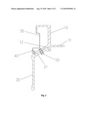
[0014]FIG. 2 is a sectional view of the topside beam of the invention. As shown in FIG. 2, the topside beam of the invention comprises: an upper topside beam which is comprised of an upper web beam 10, an upper left wing beam 12 and an upper right beam 11; and a lower topside beam which is comprised of a lower web beam 20 and a lower right wing beam 21. As for the upper topside beam, a section of the upper web beam 10 has a shape of an inverted "L"; the upper left wing beam 12 and the upper right wing beam 11 are oppositely connected to both sides of the upper web beam 10, respectively, at positions adjacent to a lower end of the upper web beam 10, and the upper left wing beam 12 inclines downwardly in respect to the upper web beam 10, the upper right wing beam 11 and the upper web beam 10 form an angle of 90°. Here, the inclination angle of the upper left wing beam 12 in respect to the upper web beam 10 is preferably 120°. Additionally, as for the lower topside beam, the lower right wing beam 21 is connected to the right side of the lower web beam 20 at a location adjacent to an upper end of the lower web beam 20, and the lower right wing beam 21 inclines upwardly in respect to the lower web beam 20 and is parallel to the upper left wing beam 12. Besides, in assembling, the upper left wing beam 12 and the lower right wing beam 21 are tightly connected by a rivet 50.
[0015]Additionally, one end of an exterior decorative plate 30 made of a mirror finished stainless steel is riveted to outside of a top end of the upper web beam 10, the other end of the exterior decorative plate is inserted to an upper end of the lower web beam 20, and decorative lace 40 made of a color PVC is adhered between the mirror finished stainless steel decorative plate 30 and the upper end of the lower web beam 20, so as to make the appearance of the topside beam of the invention more beautiful. And furthermore, according to various requirements of users, the appearances and colors of the mirror finished stainless decorative plate and the color PVC decorative lace can be changed.
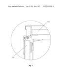
[0016]Next, an assembling process for the topside beam of the invention will be described by referring FIG. 3 hereinbelow. The structural characteristics and application of the invention may be explained more detailedly by illustrating the assembling process thereof. FIG. 3 is a local sectional view showing a container assembled with the topside beam of the invention. As shown in FIG. 3, firstly, the upper topside beams are mounted on both sides of a roof plate 100 to form a main frame of the roof plate, so as to implement a separate fabrication of the roof plate. Secondly, a lower topside beam is mounted on a side plate 200 to form a main frame of the side plate, so as to implement a separate fabrication of the side plate.
[0017]Then, the roof plate 100, which has been mounted with the upper topside beam, and the side plate 200, which has been mounted with the lower topside beam, are connected together by the rivet 50. Of course, the connecting manners of the topside beam of the invention are not limited to those mentioned above, other manners such as a bolt connection, etc. are also possible.
[0018]Therefore, the topside beam of the invention may implement separate fabrication and separate transportation of the roof plate and side plate of the container, so as to facilitate transportation and maintenance.
Claims:
1. A topside beam comprising:an upper topside beam comprised of an upper
web beam, an upper left wing beam and an upper right wing beam, wherein a
section of the upper web beam has a shape of an inverted "L"; the upper
left wing beam and the upper right wing beam are oppositely connected to
both sides of the upper web beam, respectively, at positions adjacent to
a lower end of the upper web beam; andthe upper left wing beam inclines
downwardly in respect to the upper web beam, the upper right wing beam
and the upper web beam from an angel of 90.degree.;a lower topside beam
comprised of a lower web beam and a lower right wing beam, wherein the
lower right wing beam is connected to a right side of the lower web beam
at a position adjacent to an upper end of the lower web beam, and the
lower right wing beam inclines upwardly in respect to the lower web beam
and is parallel to the upper left wing beam; andthe upper left wing beam
and the lower right wing beam are tightly connected by a connecting
member.
2. The topside beam according to claim 1, wherein the upper left wing beam inclines downwardly 120.degree. in respect to the upper web beam.
3. The topside beam according to claim 1, wherein one end of an exterior decorative plate is riveted to outside of a top end of the upper web beam, and the other end of the exterior decorative plate is inserted to an upper end of the lower web beam; and a decorative lace is adhered between the exterior decorative plate and the upper end of the lower web beam.
4. The topside beam according to claim 3, wherein the exterior decorative plate is made of a mirror finished stainless steel, and the decorative lace is made of a color PVC.
Description:
FIELD OF THE INVENTION
[0001]The present invention relates to a connection structure of a roof plate and a side plate in a container, and more particularly a topside beam of the container.
BACKGROUND OF THE INVENTION
[0002]FIG. 1 is a sectional view of a topside beam in the prior art. As shown in FIG. 1, because the topside beam 1 in the prior art has an integrated structure, it cannot be transported separately from a roof plate and a side plate of the container, as a result, it is not easy to transport the containers in batches.
SUMMARY OF THE INVENTION
[0003]According to the above problem, an object of the invention is to provide a topside beam for facilitating transportation.
[0004]For solving the above problem, the invention is implemented by the following technical solutions.
[0005]A topside beam comprises an upper topside beam and a lower topside beam, wherein the upper topside beam is comprised of an upper web beam, an upper left wing beam and an upper right wing beam; the section of the upper web beam has a shape of an inverted "L"; the upper left wing beam and the upper right wing beam are connected oppositely to both sides of the upper web beam, respectively, at positions adjacent to a lower end of the upper web beam; and the upper left wing beam inclines downwardly in respect to the upper web beam, the upper right wing beam and the upper web beam form an angle of 90°. Moreover, the lower topside beam is comprised of a lower web beam and a lower right wing beam, wherein the lower right wing beam is connected to a right side of the lower web beam at a location adjacent to an upper end of the lower web beam; the lower right wing beam inclines upwardly in respect to the lower web beam and is parallel to the upper left wing beam. Additionally, the upper topside beam and the lower topside beam are tightly connected by a connecting member.
[0006]Furthermore, the upper left wing beam opposite to the upper web beam inclines downwardly 120°.
[0007]Additionally, one end of an exterior decorative is riveted to outside of a top end of the upper web beam, the other end is inserted into the upper end of the lower web beam, and a trimming is adhered between the exterior decorative and the upper end of the lower web beam.
[0008]And, the exterior decorative is made of a mirror finished stainless steel, and the trimming made of color PVC.
[0009]As compared with the prior art, it is available to conduct the separate fabrication and the separate transportation of the roof plate and side plate of the container, by means of the topside beam of the invention, so as to facilitate the transportation and maintenance.
BRIEF DESCRIPTION OF DRAWINGS
[0010]FIG. 1 is a sectional view of a topside beam in the prior art;
[0011]FIG. 2 is a sectional view of a topside beam of the invention;
[0012]FIG. 3 is a local sectional view of a container assembled with the topside beam of the invention.
DETAILED DESCRIPTION OF THE PREFERRED EMBODIMENTS
[0013]A topside beam of the invention will be described in detail by referring FIGS. 2 and 3 hereinbelow.
[0014]FIG. 2 is a sectional view of the topside beam of the invention. As shown in FIG. 2, the topside beam of the invention comprises: an upper topside beam which is comprised of an upper web beam 10, an upper left wing beam 12 and an upper right beam 11; and a lower topside beam which is comprised of a lower web beam 20 and a lower right wing beam 21. As for the upper topside beam, a section of the upper web beam 10 has a shape of an inverted "L"; the upper left wing beam 12 and the upper right wing beam 11 are oppositely connected to both sides of the upper web beam 10, respectively, at positions adjacent to a lower end of the upper web beam 10, and the upper left wing beam 12 inclines downwardly in respect to the upper web beam 10, the upper right wing beam 11 and the upper web beam 10 form an angle of 90°. Here, the inclination angle of the upper left wing beam 12 in respect to the upper web beam 10 is preferably 120°. Additionally, as for the lower topside beam, the lower right wing beam 21 is connected to the right side of the lower web beam 20 at a location adjacent to an upper end of the lower web beam 20, and the lower right wing beam 21 inclines upwardly in respect to the lower web beam 20 and is parallel to the upper left wing beam 12. Besides, in assembling, the upper left wing beam 12 and the lower right wing beam 21 are tightly connected by a rivet 50.
[0015]Additionally, one end of an exterior decorative plate 30 made of a mirror finished stainless steel is riveted to outside of a top end of the upper web beam 10, the other end of the exterior decorative plate is inserted to an upper end of the lower web beam 20, and decorative lace 40 made of a color PVC is adhered between the mirror finished stainless steel decorative plate 30 and the upper end of the lower web beam 20, so as to make the appearance of the topside beam of the invention more beautiful. And furthermore, according to various requirements of users, the appearances and colors of the mirror finished stainless decorative plate and the color PVC decorative lace can be changed.
[0016]Next, an assembling process for the topside beam of the invention will be described by referring FIG. 3 hereinbelow. The structural characteristics and application of the invention may be explained more detailedly by illustrating the assembling process thereof. FIG. 3 is a local sectional view showing a container assembled with the topside beam of the invention. As shown in FIG. 3, firstly, the upper topside beams are mounted on both sides of a roof plate 100 to form a main frame of the roof plate, so as to implement a separate fabrication of the roof plate. Secondly, a lower topside beam is mounted on a side plate 200 to form a main frame of the side plate, so as to implement a separate fabrication of the side plate.
[0017]Then, the roof plate 100, which has been mounted with the upper topside beam, and the side plate 200, which has been mounted with the lower topside beam, are connected together by the rivet 50. Of course, the connecting manners of the topside beam of the invention are not limited to those mentioned above, other manners such as a bolt connection, etc. are also possible.
[0018]Therefore, the topside beam of the invention may implement separate fabrication and separate transportation of the roof plate and side plate of the container, so as to facilitate transportation and maintenance.
User Contributions:
Comment about this patent or add new information about this topic:
Images included with this patent application:
 |  |
 |  |
| New patent applications in this class: | |
| Date | Title |
|---|---|
| 2017-08-17 | Sheet metal framing member having a j-shaped flange |
| 2016-01-07 | Bar for a support structure for a false ceiling and production process for producing the bar |
| 2015-12-17 | Bar of a support structure for a false ceiling and working process for working the bar |
| 2015-12-10 | Deck system and components thereof, and methods of assembling and disassembling deck systems and components |
| 2015-10-22 | Interlocking asymmetric universal construction block |
| New patent applications from these inventors: | |
| Date | Title |
|---|---|
| 2012-11-22 | Refrigerator van |
| 2010-08-26 | Inner top corner connector of container body |
| Top Inventors for class "Static structures (e.g., buildings)" | |
| Rank | Inventor's name |
|---|---|
| 1 | Darko Pervan |
| 2 | Gregory F. Jacobs |
| 3 | Husnu M. Kalkanoglu |
| 4 | Ronald P. Hohmann, Jr. |
| 5 | Mark Cappelle |