Patent application title: PLASTIC BEEHIVE
Inventors:
Muzaffer Yildirim (Istanbul, TR)
IPC8 Class: AA01K4706FI
USPC Class:
449 14
Class name: Hive with ventilator in cover
Publication date: 2010-08-12
Patent application number: 20100203802
ates to demounted beehives wherein the air
circulation is realized effectively and the heat isolation is enhanced.
The beehive essentially comprises one or more body (5), a top cover (2)
and also a lower cover (7).Claims:
1. A beehive (1) comprising a lower cover (7) which closes the bottom part
of the hive (1), a top cover (2) which closes top of the hive (1), a body
(5) which is composed of at least one layer (6), walls (4) which compose
the layers (6) and connected to each other by shrink-fit, locking latches
(8) which provides the connection of the layers (6) to each other and
also the carriage of the hive; characterized by the louver (3) which is
present on the top cover (2) and provides the ventilation and ventilation
channels (9) which are present on the lower cover (7) and provide the air
circulation.
2. A beehive (1) according to claim 1 characterized by the walls (4) which are produced with blow moulding technology and whose inside is empty, wherein there are nails (10) on the edges of the mutual two of them and there are housings (11) in which these nails (10) are fastened by shrink-fit on the edges of the other two mutual walls.
3. A beehive (1) according to claim 1 characterized by the walls (4) which are provided to be the fastened to each other by screw instead of the nails (10).
4. A beehive (1) according to claim 1, 2 or 3 characterized by a top cover (2) closing the top of the hive (1) and comprising a louver (3) to provide air circulation, a gauze filter which closes the louver (3) and prevents the bees to go out or the entrance of a foreign substance from the outside to the inside while providing the air circulation.
5. A beehive (1) according to any one of the abovementioned claims characterized by a lower cover (7) which closes the bottom of the hive (1) and wherein there are four ventilation channels (9) below it.
6. A beehive (1) according to any one of the abovementioned claims characterized by a lower cover (7) comprising ventilation channels (9) having a ventilation grille (12) whose inside is in form of screw, a filter bottom grating (13), which is placed into this grille, a filter (14) present on this, a filter top grating (15) holding the filter and a ventilation screw (16) on all of them which can be fitted and displaced by turning into the ventilation grille (12).
7. A beehive (1) according to any one of the abovementioned claims characterized by the locking latch (8) which is fastened to the mutual two walls (4) of the hive (1) in order to fasten the layers (6) to each other, fastened to the upper one of the layer (6) which will be fastened to each other, and which carries out the locking by means of attaching of the handle (24) to the hanger (25) and closing the tongue (23); comprising a hanger (25), a handle (24) which fastened to the bottom layer (6) and realizes locking by means of attaching to the hanger (25), a tongue (23) to which the handle (24) is connected by the holes and a holder (22) which is used in carriage of the hive (1).
8. A beehive (1) according to any one of the abovementioned claims characterized by the upper bearing apparatus (17) and the lower bearing apparatus (18) which are present on the mutual inner sides of the two of the walls (4) composing the layers (6) to attach the honey frames inside the layers (6) and which are in form of serrated in such a manner that the honey frames will be attached.Description:
FIELD OF THE INVENTION
[0001]The present invention relates to demounted beehives wherein the air circulation is realized effectively and the heat isolation is enhanced.
BACKGROUND OF THE INVENTION
[0002]The beehives known in the state of the art are produced from wood, metal or plastic. The beehives take up a lot of space by volume and this causes carrying problems. In addition the ventilation and the heat isolation of the beehives are not on desired level and this leads to not being able to obtain the appropriate conditions for the bees.
[0003]In French patent document No. FR2540339 which is within the state of the art, a beehive wherein the walls are fastened to each other by shrink-fit without requiring rawlplug is mentioned.
[0004]In Greek patent document No. GR1005104 which is within the state of the art, a hive wherein the walls are fastened to each other by shrink-fit is mentioned. The walls which have been engaged to each other by shrink-fit in this hive provide the isolation so as not to allow fluid transition.
[0005]In Turkish utility model document No. TR 2003 02332 Y which is within the state of the art, a heat isolated plastic beehive which is produced with blow moulding technology from polyethylene, polystyrene and polypropylene and has walls whose inner surfaces are empty is mentioned.
SUMMARY OF THE INVENTION
[0006]The objective of the present invention is to realize a beehive wherein the air circulation is realized effectively and the heat isolation is enhanced.
[0007]Another objective of the present invention is to realize a beehive which is demountable and thus can be carried easier by taking up less space while in demounted condition.
[0008]The beehive realized to fulfill the objective of the present invention is described in claims. The beehive essentially comprises one or more body, a top cover and also a lower cover. The body is produced with blow moulding technology and its inside is empty. By filling these cavities with polyurethane, the isolation is provided. The body may be composed of one or more floor. Each floor is composed by fastening four walls to one another. These walls are locked to each other with cavity-core nail system. Thus additional requirements like rawlplug, screw, etc. are not needed. On the edge of two of the walls there are nails which will provide the shrink-fit and on the edges of the other two walls there are housings in which the nails will settle. The nails settle in these housings by fitting in stretchingly and thus realize the locking.
[0009]The layers are locked to each other with locking system, by means of fitting on one another. These locking latches both provide engagement of layers to each other and to carry the hive easily with the handle that it has.
[0010]On the bottom of the hive, there is a lower cover on which the layers are settled. On the lower cover, there are bee entrance tunnels wherein the bees enter. Also below the lower cover, there are ventilation channels which are consisted of several pieces and can be cleaned by dismantling.
[0011]On top of the hive, there is a top cover. The louvers which are located on the top cover enable air inlet. The ventilation channels that are present on the lower cover and the louvers that are present on the top cover enable the realization of air circulation in the hive effectively.
DETAILED DESCRIPTION OF THE INVENTION
[0012]The beehive realized to fulfill the objective of the present invention is illustrated in the accompanying figures, in which:
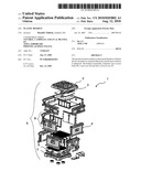
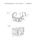
[0013]FIG. 1 is the exploded view of the inventive hive.
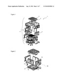
[0014]FIG. 2 is the exploded view of a single-layered embodiment of the inventive hive.
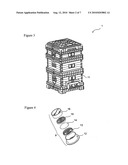
[0015]FIG. 3 is the perspective view of the hive.
[0016]FIG. 4 is the exploded view of the ventilation channels.
[0017]FIG. 5 is the exploded view of the inner parts of the hive.
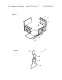
[0018]FIG. 6 is the perspective view of the locking latch.
[0019]FIG. 7 is the perspective view of the walls.
[0020]FIG. 8 is the perspective view of an embodiment of the hive wherein the walls of them are fastened to each other with screws.
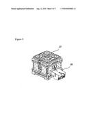
[0021]FIG. 9 is the perspective view of the hive entrance while the pollen trap is being attached.
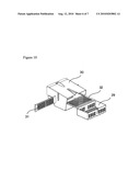
[0022]FIG. 10 is the exploded view of the pollen trap.
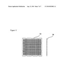
[0023]FIG. 11 is the top and side view of the queen bee section filter.
[0024]The parts shown in the figures are individually numbered, where the numbers refer to the following: [0025]1. Hive [0026]2. Top cover [0027]3. Louver [0028]4. Wall [0029]5. Body [0030]6. Layer [0031]7. Lower cover [0032]8. Locking latch [0033]9. Ventilation channel [0034]10. Nail [0035]11. Housing [0036]12. Ventilation grille [0037]13. Lower filter grating [0038]14. Filter [0039]15. Filter top grating [0040]16. Ventilation screw [0041]17. Upper bearing apparatus [0042]18. Lower bearing apparatus [0043]19. Groove [0044]20. Varoe filter [0045]21. Drawer [0046]22. Holder [0047]23. Tongue [0048]24. Handle [0049]25. Hanger [0050]26. Sun shield [0051]27. Channel [0052]28. Pollen trap [0053]29. Pollen trap drawer [0054]30. Pollen trap body [0055]31. Pollen filter [0056]32. Pollen strainer [0057]33. Queen bee filter [0058]34. Rib
[0059]The inventive hive (1) comprises a lower cover (7) which closes the bottom part of the hive (1), a top cover (2) which closes top of the hive (1), a body (5) which is composed of at least one layer (6), walls (4) which compose the layers (6) and connected to each other by shrink-fit, locking latches (8) which provide the connection of the layers (6) to each other and also the carriage of the hive, louver (3) which is present on the top cover (2) and provides the ventilation and ventilation channels (9) which are present on the lower cover (7) and provide the air circulation.
[0060]The body (5) is composed of one or more layers (6). Whereas the layers (6) are composed of walls (4) which are connected to each other by shrink-fit. The walls (4) are produced with blow moulding technology and their inside is empty. By filling these cavities with polyurethane, the isolation is provided. There is a top cover (2) which closes top of the body (5). Also the bottom of the body (5) is closed by means of fastening the bottom layer on a lower cover (7).
[0061]There are nails (10) on the edges of two of the walls (4) which compose a layer (6) whereas there are housings (11) wherein these nails (10) are fastened by shrink-fit on the edges of the other two walls. The nails can settle in housing (11) by fitting in stretchingly. Also in another embodiment, a screwed structure can be used instead of these nails (10). The fastening of the screws by settling to the housing (11) instead of the nail (10) can be provided.
[0062]The top cover (2) closes the top of the hive (1). The top cover (2) settles on the top layer as cavity-core, by layer. There is a louver (3) on the top cover (2) in order to provide air circulation. A climatic environment is formed by the supply of air circulation and also moisture formation is prevented. While the air transition is provided owing to the gauze filter which closes the louver (3), it is not possible to for the bees to go out or the entrance of a foreign substance from the outside to the inside. Also owing to the structure of the louver (3), rain-waters and wind are prevented to get into directly.
[0063]The layers (6) composing the hive (1) settle on the lower cover (7) and close the bottom of the hive (1). There are four ventilation channels (9) on the cover (7). These ventilation channels (9) provide the air circulation of the hive (1) together with the louvers (3) which are present on the top cover (2). The ventilation channels (9) are made screwed so as to be easily dismantled to be able to make the periodic cleanings. There are a ventilation grille (12), a filter bottom grating (13) placed into this grille, a filter (14) present on this, a filter top grating (15) holding the filter and a ventilation screw (16) on all of them. The edges of the ventilation screw (16) and the interior of the ventilation grille (12) are in screwed sructure and the ventilation screw (16) is fitted and displaced by turning into the ventilation grille (12). By this means, easily disconnection from each other and easily displacement of the parts has been provided and this situation has provided advantage for the periodic cleaning.
[0064]In order to fasten the layers (6) to each other, there are two locking latches (8) on the two sides of the hive (1). The hanger (25) which is the part of the locking latch (8) that will make the locking, is on the upper part whereas the handle (24) which will carry out the locking by means of attaching on the hanger, is on the lower part. The hanger (25) of the locking latch (8) is attached to the upper layer which is one of the layers that will be fastened to the each other whereas the handle (24), the tongue (23) and the holder (22) are attached to the lower layer. The handle (24) can move downward and upward by means of moving the tongue (23) in the manner that it makes spring movement. In addition, the handle (24) moves circularly on condition that the holes to which it is being connected to the tongue (23) are center. The handle (24) is pulled downward and the locking is carried out by means of attaching of the handle (24) to the hanger (25) and closing the tongue (23) in consequence of these movements. The holder (22) is used in carrying the hive (1), independently of the locking.
[0065]There are upper bearing apparatus (17) and lower bearing apparatus (18) in the mutual inner sides of the two of the walls (4) to attach the honey frames inside the layers (6). These bearing apparatuses (17 and 18) are attached to the grooves (19). The upper bearing apparatus (17) is shaped in such a manner that one side is serrated and the other side is flat. When the serrated part is attached to the groove (19) in such a manner that it will be on the upper side, the frames settle on this serrated part and the moving of the frames is prevented. The lower bearing apparatus (18) is in a combed structure as well and these combs prevent the moving of the frame which is settled between the teeth.
[0066]There is varoe filter (20) just on the lower cover (7). Owing to this filter (20) the bees are protected from harmful elements. The harmful elements which pass under this filter (20) are accumulated in a drawer (21) and the cleaning of this drawer by means of removing can be possible.
[0067]There is sun shield (26) which covers the entrances wherein the bees enter the hive, on the hive (1). These sun shields (26) protect the entrances against sun. Pollen trap (28) can be attached to the place wherein the bees enter, instead of the sun shield (26). This pollen trap (28) serves to collect the pollens on the bees during their entrance into the hive and to accumulate them in a drawer (29). While the bees are entering the hive, during they are passing through the thin holed pollen filter (31) via the spilling of pollens which have been accumulated on them, these pollens are provided not to enter into the hive. The pollen trap (28) comprises a pollen drawer (29), a body (30), a pollen filter (31) and also a pollen strainer (32).
[0068]Upon the top cover (2) there is a channel (27) extending from end to end. More than one hive (1) which is superposed with this channel (27) can be fastened by a rope and the rope can stand without sliding by the positioning of the rope to this channel (27).
[0069]In order to prevent the queen bee which is present in the bottom layer of the hive (1) to climb up layers, there is queen bee filter (33) between the layers. The holes on this filter enable the worker bees to pass but they don't allow the queen bee to pass. The sizes of the holes are made in such a manner that only the worker bees can pass. Besides, there are ribs (34) in such a manner that they protrude below the filter (33). These ribs (34) prevent the filter (33) to become deformed by abutting the frames. At the same time, the ribs which are similarly present on seperators that are between the layers, prevent the seperators to become deformed.
Claims:
1. A beehive (1) comprising a lower cover (7) which closes the bottom part
of the hive (1), a top cover (2) which closes top of the hive (1), a body
(5) which is composed of at least one layer (6), walls (4) which compose
the layers (6) and connected to each other by shrink-fit, locking latches
(8) which provides the connection of the layers (6) to each other and
also the carriage of the hive; characterized by the louver (3) which is
present on the top cover (2) and provides the ventilation and ventilation
channels (9) which are present on the lower cover (7) and provide the air
circulation.
2. A beehive (1) according to claim 1 characterized by the walls (4) which are produced with blow moulding technology and whose inside is empty, wherein there are nails (10) on the edges of the mutual two of them and there are housings (11) in which these nails (10) are fastened by shrink-fit on the edges of the other two mutual walls.
3. A beehive (1) according to claim 1 characterized by the walls (4) which are provided to be the fastened to each other by screw instead of the nails (10).
4. A beehive (1) according to claim 1, 2 or 3 characterized by a top cover (2) closing the top of the hive (1) and comprising a louver (3) to provide air circulation, a gauze filter which closes the louver (3) and prevents the bees to go out or the entrance of a foreign substance from the outside to the inside while providing the air circulation.
5. A beehive (1) according to any one of the abovementioned claims characterized by a lower cover (7) which closes the bottom of the hive (1) and wherein there are four ventilation channels (9) below it.
6. A beehive (1) according to any one of the abovementioned claims characterized by a lower cover (7) comprising ventilation channels (9) having a ventilation grille (12) whose inside is in form of screw, a filter bottom grating (13), which is placed into this grille, a filter (14) present on this, a filter top grating (15) holding the filter and a ventilation screw (16) on all of them which can be fitted and displaced by turning into the ventilation grille (12).
7. A beehive (1) according to any one of the abovementioned claims characterized by the locking latch (8) which is fastened to the mutual two walls (4) of the hive (1) in order to fasten the layers (6) to each other, fastened to the upper one of the layer (6) which will be fastened to each other, and which carries out the locking by means of attaching of the handle (24) to the hanger (25) and closing the tongue (23); comprising a hanger (25), a handle (24) which fastened to the bottom layer (6) and realizes locking by means of attaching to the hanger (25), a tongue (23) to which the handle (24) is connected by the holes and a holder (22) which is used in carriage of the hive (1).
8. A beehive (1) according to any one of the abovementioned claims characterized by the upper bearing apparatus (17) and the lower bearing apparatus (18) which are present on the mutual inner sides of the two of the walls (4) composing the layers (6) to attach the honey frames inside the layers (6) and which are in form of serrated in such a manner that the honey frames will be attached.
Description:
FIELD OF THE INVENTION
[0001]The present invention relates to demounted beehives wherein the air circulation is realized effectively and the heat isolation is enhanced.
BACKGROUND OF THE INVENTION
[0002]The beehives known in the state of the art are produced from wood, metal or plastic. The beehives take up a lot of space by volume and this causes carrying problems. In addition the ventilation and the heat isolation of the beehives are not on desired level and this leads to not being able to obtain the appropriate conditions for the bees.
[0003]In French patent document No. FR2540339 which is within the state of the art, a beehive wherein the walls are fastened to each other by shrink-fit without requiring rawlplug is mentioned.
[0004]In Greek patent document No. GR1005104 which is within the state of the art, a hive wherein the walls are fastened to each other by shrink-fit is mentioned. The walls which have been engaged to each other by shrink-fit in this hive provide the isolation so as not to allow fluid transition.
[0005]In Turkish utility model document No. TR 2003 02332 Y which is within the state of the art, a heat isolated plastic beehive which is produced with blow moulding technology from polyethylene, polystyrene and polypropylene and has walls whose inner surfaces are empty is mentioned.
SUMMARY OF THE INVENTION
[0006]The objective of the present invention is to realize a beehive wherein the air circulation is realized effectively and the heat isolation is enhanced.
[0007]Another objective of the present invention is to realize a beehive which is demountable and thus can be carried easier by taking up less space while in demounted condition.
[0008]The beehive realized to fulfill the objective of the present invention is described in claims. The beehive essentially comprises one or more body, a top cover and also a lower cover. The body is produced with blow moulding technology and its inside is empty. By filling these cavities with polyurethane, the isolation is provided. The body may be composed of one or more floor. Each floor is composed by fastening four walls to one another. These walls are locked to each other with cavity-core nail system. Thus additional requirements like rawlplug, screw, etc. are not needed. On the edge of two of the walls there are nails which will provide the shrink-fit and on the edges of the other two walls there are housings in which the nails will settle. The nails settle in these housings by fitting in stretchingly and thus realize the locking.
[0009]The layers are locked to each other with locking system, by means of fitting on one another. These locking latches both provide engagement of layers to each other and to carry the hive easily with the handle that it has.
[0010]On the bottom of the hive, there is a lower cover on which the layers are settled. On the lower cover, there are bee entrance tunnels wherein the bees enter. Also below the lower cover, there are ventilation channels which are consisted of several pieces and can be cleaned by dismantling.
[0011]On top of the hive, there is a top cover. The louvers which are located on the top cover enable air inlet. The ventilation channels that are present on the lower cover and the louvers that are present on the top cover enable the realization of air circulation in the hive effectively.
DETAILED DESCRIPTION OF THE INVENTION
[0012]The beehive realized to fulfill the objective of the present invention is illustrated in the accompanying figures, in which:
[0013]FIG. 1 is the exploded view of the inventive hive.
[0014]FIG. 2 is the exploded view of a single-layered embodiment of the inventive hive.
[0015]FIG. 3 is the perspective view of the hive.
[0016]FIG. 4 is the exploded view of the ventilation channels.
[0017]FIG. 5 is the exploded view of the inner parts of the hive.
[0018]FIG. 6 is the perspective view of the locking latch.
[0019]FIG. 7 is the perspective view of the walls.
[0020]FIG. 8 is the perspective view of an embodiment of the hive wherein the walls of them are fastened to each other with screws.
[0021]FIG. 9 is the perspective view of the hive entrance while the pollen trap is being attached.
[0022]FIG. 10 is the exploded view of the pollen trap.
[0023]FIG. 11 is the top and side view of the queen bee section filter.
[0024]The parts shown in the figures are individually numbered, where the numbers refer to the following: [0025]1. Hive [0026]2. Top cover [0027]3. Louver [0028]4. Wall [0029]5. Body [0030]6. Layer [0031]7. Lower cover [0032]8. Locking latch [0033]9. Ventilation channel [0034]10. Nail [0035]11. Housing [0036]12. Ventilation grille [0037]13. Lower filter grating [0038]14. Filter [0039]15. Filter top grating [0040]16. Ventilation screw [0041]17. Upper bearing apparatus [0042]18. Lower bearing apparatus [0043]19. Groove [0044]20. Varoe filter [0045]21. Drawer [0046]22. Holder [0047]23. Tongue [0048]24. Handle [0049]25. Hanger [0050]26. Sun shield [0051]27. Channel [0052]28. Pollen trap [0053]29. Pollen trap drawer [0054]30. Pollen trap body [0055]31. Pollen filter [0056]32. Pollen strainer [0057]33. Queen bee filter [0058]34. Rib
[0059]The inventive hive (1) comprises a lower cover (7) which closes the bottom part of the hive (1), a top cover (2) which closes top of the hive (1), a body (5) which is composed of at least one layer (6), walls (4) which compose the layers (6) and connected to each other by shrink-fit, locking latches (8) which provide the connection of the layers (6) to each other and also the carriage of the hive, louver (3) which is present on the top cover (2) and provides the ventilation and ventilation channels (9) which are present on the lower cover (7) and provide the air circulation.
[0060]The body (5) is composed of one or more layers (6). Whereas the layers (6) are composed of walls (4) which are connected to each other by shrink-fit. The walls (4) are produced with blow moulding technology and their inside is empty. By filling these cavities with polyurethane, the isolation is provided. There is a top cover (2) which closes top of the body (5). Also the bottom of the body (5) is closed by means of fastening the bottom layer on a lower cover (7).
[0061]There are nails (10) on the edges of two of the walls (4) which compose a layer (6) whereas there are housings (11) wherein these nails (10) are fastened by shrink-fit on the edges of the other two walls. The nails can settle in housing (11) by fitting in stretchingly. Also in another embodiment, a screwed structure can be used instead of these nails (10). The fastening of the screws by settling to the housing (11) instead of the nail (10) can be provided.
[0062]The top cover (2) closes the top of the hive (1). The top cover (2) settles on the top layer as cavity-core, by layer. There is a louver (3) on the top cover (2) in order to provide air circulation. A climatic environment is formed by the supply of air circulation and also moisture formation is prevented. While the air transition is provided owing to the gauze filter which closes the louver (3), it is not possible to for the bees to go out or the entrance of a foreign substance from the outside to the inside. Also owing to the structure of the louver (3), rain-waters and wind are prevented to get into directly.
[0063]The layers (6) composing the hive (1) settle on the lower cover (7) and close the bottom of the hive (1). There are four ventilation channels (9) on the cover (7). These ventilation channels (9) provide the air circulation of the hive (1) together with the louvers (3) which are present on the top cover (2). The ventilation channels (9) are made screwed so as to be easily dismantled to be able to make the periodic cleanings. There are a ventilation grille (12), a filter bottom grating (13) placed into this grille, a filter (14) present on this, a filter top grating (15) holding the filter and a ventilation screw (16) on all of them. The edges of the ventilation screw (16) and the interior of the ventilation grille (12) are in screwed sructure and the ventilation screw (16) is fitted and displaced by turning into the ventilation grille (12). By this means, easily disconnection from each other and easily displacement of the parts has been provided and this situation has provided advantage for the periodic cleaning.
[0064]In order to fasten the layers (6) to each other, there are two locking latches (8) on the two sides of the hive (1). The hanger (25) which is the part of the locking latch (8) that will make the locking, is on the upper part whereas the handle (24) which will carry out the locking by means of attaching on the hanger, is on the lower part. The hanger (25) of the locking latch (8) is attached to the upper layer which is one of the layers that will be fastened to the each other whereas the handle (24), the tongue (23) and the holder (22) are attached to the lower layer. The handle (24) can move downward and upward by means of moving the tongue (23) in the manner that it makes spring movement. In addition, the handle (24) moves circularly on condition that the holes to which it is being connected to the tongue (23) are center. The handle (24) is pulled downward and the locking is carried out by means of attaching of the handle (24) to the hanger (25) and closing the tongue (23) in consequence of these movements. The holder (22) is used in carrying the hive (1), independently of the locking.
[0065]There are upper bearing apparatus (17) and lower bearing apparatus (18) in the mutual inner sides of the two of the walls (4) to attach the honey frames inside the layers (6). These bearing apparatuses (17 and 18) are attached to the grooves (19). The upper bearing apparatus (17) is shaped in such a manner that one side is serrated and the other side is flat. When the serrated part is attached to the groove (19) in such a manner that it will be on the upper side, the frames settle on this serrated part and the moving of the frames is prevented. The lower bearing apparatus (18) is in a combed structure as well and these combs prevent the moving of the frame which is settled between the teeth.
[0066]There is varoe filter (20) just on the lower cover (7). Owing to this filter (20) the bees are protected from harmful elements. The harmful elements which pass under this filter (20) are accumulated in a drawer (21) and the cleaning of this drawer by means of removing can be possible.
[0067]There is sun shield (26) which covers the entrances wherein the bees enter the hive, on the hive (1). These sun shields (26) protect the entrances against sun. Pollen trap (28) can be attached to the place wherein the bees enter, instead of the sun shield (26). This pollen trap (28) serves to collect the pollens on the bees during their entrance into the hive and to accumulate them in a drawer (29). While the bees are entering the hive, during they are passing through the thin holed pollen filter (31) via the spilling of pollens which have been accumulated on them, these pollens are provided not to enter into the hive. The pollen trap (28) comprises a pollen drawer (29), a body (30), a pollen filter (31) and also a pollen strainer (32).
[0068]Upon the top cover (2) there is a channel (27) extending from end to end. More than one hive (1) which is superposed with this channel (27) can be fastened by a rope and the rope can stand without sliding by the positioning of the rope to this channel (27).
[0069]In order to prevent the queen bee which is present in the bottom layer of the hive (1) to climb up layers, there is queen bee filter (33) between the layers. The holes on this filter enable the worker bees to pass but they don't allow the queen bee to pass. The sizes of the holes are made in such a manner that only the worker bees can pass. Besides, there are ribs (34) in such a manner that they protrude below the filter (33). These ribs (34) prevent the filter (33) to become deformed by abutting the frames. At the same time, the ribs which are similarly present on seperators that are between the layers, prevent the seperators to become deformed.
User Contributions:
Comment about this patent or add new information about this topic:
| People who visited this patent also read: | |
| Patent application number | Title |
|---|---|
| 20130260112 | IN-MOLD GRAIN SKIN LAMINATION FOR INTERIOR TRIM PANEL WITH DECORATIVE APPLIQUE |
| 20130260111 | LAMINATED ARTICLES HAVING DISCONTINUOUS BONDED REGIONS |
| 20130260110 | STRUCTURE FORMING APPARATUS, STRUCTURE MANUFACTURING METHOD, AND STRUCTURE |
| 20130260109 | PHOTOCURABLE RESIN COMPOSITION, DRY FILM, CURED PRODUCT AND PRINTED WIRING BOARD |
| 20130260108 | PHOTO-CURING POLYSILOXAN COMPOSITION AND APPLICATIONS THEREOF |
Images included with this patent application:
 |  |
 |  |
 |  |
 |  |
| Similar patent applications: | |
| Date | Title |
|---|---|
| 2010-03-11 | Acoustic sensor for beehive monitoring |
| 2012-03-29 | Apparatus for continuous weight monitoring of beehives |
| Top Inventors for class "Bee culture" | |
| Rank | Inventor's name |
|---|---|
| 1 | Gene Probasco |
| 2 | Stephen Engel |
| 3 | Todd Gordon Mason |
| 4 | Stephen Adam Engel |
| 5 | Peter G. Kevan |