Patent application title: CEILING-EMBEDDED AIR CONDITIONER
Inventors:
Kenji Gajina (Fuji-Shi, JP)
Assignees:
TOSHIBA CARRIER CORPORATION
IPC8 Class: AA47B9500FI
USPC Class:
312204
Class name: Supports: cabinet structure simulation, ornamentation or with secret compartment
Publication date: 2010-08-12
Patent application number: 20100201232
conditioner, a panel fastening screw that
fastens a decorative panel to an indoor unit body embedded in a ceiling
is previously mounted to the indoor unit body and has an intermediate
portion having a small diameter with no threaded portion.Claims:
1. A ceiling-embedded air conditioner comprising:an indoor unit body
embedded in a ceiling; anda decorative panel that covers a lower surface
of the indoor unit body,wherein a panel fastening screw that fastens the
decorative panel to the indoor unit body is previously mounted to the
indoor unit body and has a small diameter portion without a threaded
portion in an intermediate portion thereof
2. The ceiling-embedded air conditioner according to claim 1, wherein a panel fastening member that fastens the decorative panel is provided on the decorative panel so as to be advanced and retracted, and the panel fastening member has a screw engaging groove that engages the panel fastening screw, and engages the panel fastening screw in an advanced state.
3. The ceiling-embedded air conditioner according to claim 1, wherein a hook is provided on the decorative panel and a hook engaging portion with which the hook engages is provided on the indoor unit body, the hook being engaged with the hook engaging portion to temporarily hang the decorative panel on the indoor unit body.
4. The ceiling-embedded air conditioner according to claim 2, wherein a hook is provided on the decorative panel and a hook engaging portion with which the hook engages is provided on the indoor unit body, the hook being engaged with the hook engaging portion to temporarily hang the decorative panel on the indoor unit body.Description:
TECHNICAL FIELD
[0001]The present invention relates to an air conditioner specifically of a ceiling-embedded type, and more particularly, to a ceiling-embedded air conditioner having an improved mounting structure of a decorative panel.
BACKGROUND ART
[0002]Generally, a ceiling-embedded air conditioner has a structure in which a decorative panel covers a lower surface of an indoor unit body embedded in a ceiling.
[0003]In a conventional mounting structure of a decorative panel to an indoor unit body, a decorative panel is temporarily hung and then fastened to the indoor unit body by a fastening screw. Otherwise, a mounting screw member including an integrated fastening screw and a temporary hanging portion is provided on the decorative panel, and it is then hung on the indoor unit and fastened by a screw (for example, Patent Document 1: Japanese Patent Laid-Open No. 2006-17342).
[0004]However, as described in Patent Document 1, the method of fastening with the attached screw provide a problem that the screw falls or is lost, or the screw is fastened in alignment with a lower hole, which reduces workability. For the method of hanging and fastening, on the body, the mounting screw member including the fastening screw and the temporary hanging portion integral with each other and provided on the decorative panel, there is no risk of falling or loss of the screw but there is a problem in workability of temporary hanging.
DISCLOSURE OF THE INVENTION
[0005]The present invention was made in consideration of the circumstances mentioned above, and an object thereof is to provide an air conditioner of a ceiling-embedded type (ceiling-embedded air conditioner) in which a decorative panel can be easily mounted to an indoor unit body.
[0006]To achieve the above-described object, the present invention provides a ceiling-embedded air conditioner including: an indoor unit body embedded in a ceiling; and a decorative panel that covers a lower surface of the indoor unit body, in which a panel fastening screw that fastens the decorative panel to the indoor unit body is previously mounted to the indoor unit body and has a small diameter portion without a threaded portion at an intermediate portion thereof.
[0007]In a preferred embodiment, a panel fastening member that fastens the decorative panel is provided on the decorative panel so as to be advanceable and retractable, and the panel fastening member has a screw engaging groove that engages the panel fastening screw, and engages the panel fastening screw in an advanced state.
[0008]A hook may be provided on the decorative panel and a hook engaging portion with which the hook engages is provided on the indoor unit body in a manner such that the hook is engaged with the hook engaging portion to temporarily hang the decorative panel on the indoor unit body.
[0009]According to the present invention, a ceiling-embedded air conditioner that allows a decorative panel to be easily mounted to an indoor unit body can be provided.
BRIEF DESCRIPTION OF THE DRAWINGS
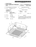
[0010]FIG. 1 is a perspective view of a ceiling-embedded air conditioner according to an embodiment of the present invention.
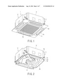
[0011]FIG. 2 is a perspective view of an indoor unit body of the ceiling-embedded air conditioner according to the embodiment of the present invention.
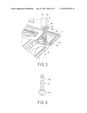
[0012]FIG. 3 is a partially enlarged perspective view of a panel fastening member, in a retracted state, used for mounting a decorative panel of the ceiling-embedded air conditioner according to the embodiment of the present invention.
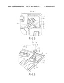
[0013]FIG. 4 is a perspective view of the panel fastening screw used in the ceiling-embedded air conditioner according to the embodiment of the present invention.
[0014]FIG. 5 is a partially enlarged plan view of the panel fastening member, in the retracted state, used in the ceiling-embedded air conditioner according to the embodiment of the present invention.
[0015]FIG. 6 is a partially enlarged perspective view of the panel fastening member, in an advanced state, used for mounting the decorative panel of the ceiling-embedded air conditioner according to the embodiment of the present invention.
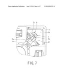
[0016]FIG. 7 is a partially enlarged plan view of the panel fastening member, in the advanced state, used in the ceiling-embedded air conditioner according to the embodiment of the present invention.
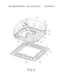
[0017]FIG. 8 is a perspective view of the decorative panel, before mounting, of the ceiling-embedded air conditioner according to the embodiment of the present invention.
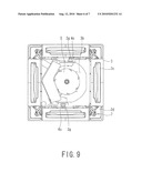
[0018]FIG. 9 is a plan view of the decorative panel, after mounting, of the ceiling-embedded air conditioner according to the embodiment of the present invention.
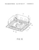
[0019]FIG. 10 is a perspective view of the decorative panel, after mounting, of the ceiling-embedded air conditioner according to the embodiment of the present invention.
BEST MODE FOR CARRYING OUT THE INVENTION
[0020]A ceiling-embedded air conditioner according to an embodiment of the present invention will be described with reference to the accompanying drawings.
[0021]FIG. 1 is a perspective view of a ceiling-embedded air conditioner according to an embodiment of the present invention, and FIG. 2 is a perspective view of an indoor unit body of the ceiling-embedded air conditioner.
[0022]As shown in FIGS. 1 and 2, the ceiling-embedded air conditioner 1 according to the embodiment of the present invention includes an indoor unit body 2 embedded in a ceiling and a decorative panel 3 that covers a lower surface of the indoor unit body 2.
[0023]The indoor unit body 2 includes a housing 4, which houses an indoor heat exchanger, not shown, an indoor blower 5 and the like.
[0024]The housing 4 is suspended from and mounted to a ceiling substrate, not shown, by means of four sets of similar suspending units 6.
[0025]As shown in an enlarged manner in FIG. 3, each of the suspending units 6 includes a suspending bolt 6a mounted to the ceiling substrate, a suspending fitting 6b mounted to one side wall 4a of the housing 4, an unshown upper-side washer and a lower-side washer 6c that vertically hold the suspending fitting 6b therebetween and through which the suspending bolt 6a passes, and an upper nut and a lower nut 6d that are threaded with the suspending bolt 6a and vertically hold the suspending fitting 6b therebetween.
[0026]Meanwhile, the decorative panel 3 includes an air inlet port 3b having an inlet grill 3a removably mounted to the central portion of the panel 3, air outlet ports 3c provided in four peripheral sides, and decorative plates 3e that are provided at four corners so as to close openings 3d. The decorative panel 3 is also mounted to the housing 4 by a mounting unit 7 so as to close a lower surface of the indoor unit body 2, that is, an opening portion 4b of the housing 4.
[0027]The mounting unit 7 is fastend to the indoor unit body 2, for example, the opening portion 4b of the housing 4, and includes a mounting piece 7a having a screw hole 7a1, a panel fastening screw 7b threaded into the screw hole 7a1, a screw through hole 3p1 provided in a panel fastening portion 3p and through which a head portion 7b1 of the panel fastening screw 7b passes, and a panel fastening member 7c mounted to the decorative panel 3 so as to be advanceable and retractable.
[0028]As shown in FIG. 4, the panel fastening screw 7b has, near a tip end, a middle portion, that is, a head portion 7b1 and a small diameter portion 7b2 having no thread between the head portion 7b1 and the tip. When the panel fastening screw 7b threaded into the screw hole 7a1 is rotated counterclockwise between the small diameter portion 7b2 and the head portion 7b1, the panel fastening screw 7b is moved down along a screw groove, but when the small diameter portion 7b2 reaches the screw hole 7a1, threading is released and the panel fastening screw 7b is no longer moved down, thereby preventing falling of the panel fastening screw 7b.
[0029]FIGS. 3 and 5 show a retracted (standby) state of the panel fastening member 7c, and FIGS. 6 and 7 show an advanced (engaged) state of the panel fastening member 7c. For example, as shown in FIG. 5, the panel fastening member 7c has a rectangular plate shape and includes a Y-shaped screw engaging groove 7c1 formed at a tip end portion thereof and a guide groove 7c2 formed near the central portion thereof. The panel fastening member 7c is mounted to the decorative panel 3 so as to be advanceable and retractable by a fastening screw 3f passing through the guide groove 7c2.
[0030]Further, as shown in FIGS. 3 and 5, the panel fastening member 7c is advanced from the retracted state toward (i.e., moved forward and rearward) the panel fastening portion 3p provided at the corner portion of the decorative panel 3, and as shown in FIGS. 6 and 7, the screw engaging groove 7c1 engages the panel fastening screw 7b passing through the screw through hole 3p1 provided in the panel fastening portion 3p, and is fastened by the panel fastening screw 7b. Thus, the decorative panel 3 is mounted to the housing 4, and the panel fastening member 7c acts to position the decorative panel 3 and functions as a washer.
[0031]As shown in FIGS. 8 and 9, temporary hanging hooks 3g, 3g are provided on opposite sides of the air inlet port 3b of the decorative panel 3, and two hook engaging portions 4c, 4c are provided in substantially opposite positions corresponding to the hooks 3g, 3g on lower portions of opposite inner walls of the housing 4.
[0032]As shown in FIGS. 9 and 10, the hooks 3g, 3g are engaged with the hook engaging portions 4c and 4c, so that the decorative panel 3 is temporarily hung on the housing 4.
[0033]The decorative panel 3 is mounted to the housing 4 using the mounting unit 7 in the following manner.
[0034]As shown in FIG. 2, the housing 4 with the panel fastening screw 7b previously mounted to the mounting piece 7a is suspended from the ceiling substrate using the suspending unit 6.
[0035]As shown in FIG. 8, with the inlet grill 3a and the decorative plate 3e previously removed, the air inlet port 3b and the operation opening 3d are opened.
[0036]As shown in FIGS. 9 and 10, the hooks 3g, 3g are engaged with the hook engaging portions 4c and 4c, and thus, the decorative panel 3 is temporarily hung on the housing 4.
[0037]As shown in FIGS. 4 and 5, in a state in which the decorative panel 3 is temporarily hung on the housing 4, the panel fastening member 7c is in the retracted state. In this state, the panel fastening screw 7b passes through the screw through hole 3p1 provided in the panel fastening portion 3p, and the screw head portion and a portion near the screw head portion is exposed outside of the screw through hole 3p1.
[0038]As shown in FIGS. 6 and 7, the panel fastening member 7c is advanced and engaged with the panel fastening screw 7b passing through the screw through hole 3p1 in the panel fastening portion 3p, and thereafter, the panel fastening member 7c is fixedly positioned by the fastening screw 3f, and the panel fastening screw 7b is then fastened. According to this manner, the panel fastening member 7c is held between the panel fastening portion 3p and the head portion 7b1 of the panel fastening screw 7b.
[0039]As shown in FIG. 1, the inlet grill 3a and the decorative plate 3e are mounted to close the air inlet port 3b and the operation opening 3d.
[0040]According to the procedure mentioned above, the mounting of the decorative panel 3 to the housing 4 has been completed.
[0041]In the above-described mounting process of the decorative panel, since the panel fastening screw is mounted to the housing, there is no risk of loss of the panel fastening screw. In addition, when the panel fastening screw is fastened, since there is no need to align the panel fastening screw with the screw hole, good workability may be provided.
[0042]Further, the decorative panel can be positioned by a simple operation of passing the head portion of the panel fastening screw through the screw through hole in the panel fastening portion and then advancing the panel fastening member, and therefore, the decorative panel can be mounted to a proper position only by fastening the panel fastening screw, thus also providing good workability.
[0043]Furthermore, since the panel fastening member is engaged with the panel fastening screw and held between the panel fastening portion and the head portion of the panel fastening screw, the decorative panel can be easily positioned and the panel fastening' member functions as a washer.
[0044]Still furthermore, the decorative panel is temporarily hung on the housing by using the hook and the hook engaging portion, and the decorative panel is mounted by the panel fastening member and the panel fastening screw, so that the mounting workability can be improved.
[0045]Still furthermore, when it is required to remove the decorative panel for the purpose of maintenance or the like, the panel fastening screw does not drop off the housing even if the panel fastening screw is excessively loosened, thus also providing good workability.
Claims:
1. A ceiling-embedded air conditioner comprising:an indoor unit body
embedded in a ceiling; anda decorative panel that covers a lower surface
of the indoor unit body,wherein a panel fastening screw that fastens the
decorative panel to the indoor unit body is previously mounted to the
indoor unit body and has a small diameter portion without a threaded
portion in an intermediate portion thereof
2. The ceiling-embedded air conditioner according to claim 1, wherein a panel fastening member that fastens the decorative panel is provided on the decorative panel so as to be advanced and retracted, and the panel fastening member has a screw engaging groove that engages the panel fastening screw, and engages the panel fastening screw in an advanced state.
3. The ceiling-embedded air conditioner according to claim 1, wherein a hook is provided on the decorative panel and a hook engaging portion with which the hook engages is provided on the indoor unit body, the hook being engaged with the hook engaging portion to temporarily hang the decorative panel on the indoor unit body.
4. The ceiling-embedded air conditioner according to claim 2, wherein a hook is provided on the decorative panel and a hook engaging portion with which the hook engages is provided on the indoor unit body, the hook being engaged with the hook engaging portion to temporarily hang the decorative panel on the indoor unit body.
Description:
TECHNICAL FIELD
[0001]The present invention relates to an air conditioner specifically of a ceiling-embedded type, and more particularly, to a ceiling-embedded air conditioner having an improved mounting structure of a decorative panel.
BACKGROUND ART
[0002]Generally, a ceiling-embedded air conditioner has a structure in which a decorative panel covers a lower surface of an indoor unit body embedded in a ceiling.
[0003]In a conventional mounting structure of a decorative panel to an indoor unit body, a decorative panel is temporarily hung and then fastened to the indoor unit body by a fastening screw. Otherwise, a mounting screw member including an integrated fastening screw and a temporary hanging portion is provided on the decorative panel, and it is then hung on the indoor unit and fastened by a screw (for example, Patent Document 1: Japanese Patent Laid-Open No. 2006-17342).
[0004]However, as described in Patent Document 1, the method of fastening with the attached screw provide a problem that the screw falls or is lost, or the screw is fastened in alignment with a lower hole, which reduces workability. For the method of hanging and fastening, on the body, the mounting screw member including the fastening screw and the temporary hanging portion integral with each other and provided on the decorative panel, there is no risk of falling or loss of the screw but there is a problem in workability of temporary hanging.
DISCLOSURE OF THE INVENTION
[0005]The present invention was made in consideration of the circumstances mentioned above, and an object thereof is to provide an air conditioner of a ceiling-embedded type (ceiling-embedded air conditioner) in which a decorative panel can be easily mounted to an indoor unit body.
[0006]To achieve the above-described object, the present invention provides a ceiling-embedded air conditioner including: an indoor unit body embedded in a ceiling; and a decorative panel that covers a lower surface of the indoor unit body, in which a panel fastening screw that fastens the decorative panel to the indoor unit body is previously mounted to the indoor unit body and has a small diameter portion without a threaded portion at an intermediate portion thereof.
[0007]In a preferred embodiment, a panel fastening member that fastens the decorative panel is provided on the decorative panel so as to be advanceable and retractable, and the panel fastening member has a screw engaging groove that engages the panel fastening screw, and engages the panel fastening screw in an advanced state.
[0008]A hook may be provided on the decorative panel and a hook engaging portion with which the hook engages is provided on the indoor unit body in a manner such that the hook is engaged with the hook engaging portion to temporarily hang the decorative panel on the indoor unit body.
[0009]According to the present invention, a ceiling-embedded air conditioner that allows a decorative panel to be easily mounted to an indoor unit body can be provided.
BRIEF DESCRIPTION OF THE DRAWINGS
[0010]FIG. 1 is a perspective view of a ceiling-embedded air conditioner according to an embodiment of the present invention.
[0011]FIG. 2 is a perspective view of an indoor unit body of the ceiling-embedded air conditioner according to the embodiment of the present invention.
[0012]FIG. 3 is a partially enlarged perspective view of a panel fastening member, in a retracted state, used for mounting a decorative panel of the ceiling-embedded air conditioner according to the embodiment of the present invention.
[0013]FIG. 4 is a perspective view of the panel fastening screw used in the ceiling-embedded air conditioner according to the embodiment of the present invention.
[0014]FIG. 5 is a partially enlarged plan view of the panel fastening member, in the retracted state, used in the ceiling-embedded air conditioner according to the embodiment of the present invention.
[0015]FIG. 6 is a partially enlarged perspective view of the panel fastening member, in an advanced state, used for mounting the decorative panel of the ceiling-embedded air conditioner according to the embodiment of the present invention.
[0016]FIG. 7 is a partially enlarged plan view of the panel fastening member, in the advanced state, used in the ceiling-embedded air conditioner according to the embodiment of the present invention.
[0017]FIG. 8 is a perspective view of the decorative panel, before mounting, of the ceiling-embedded air conditioner according to the embodiment of the present invention.
[0018]FIG. 9 is a plan view of the decorative panel, after mounting, of the ceiling-embedded air conditioner according to the embodiment of the present invention.
[0019]FIG. 10 is a perspective view of the decorative panel, after mounting, of the ceiling-embedded air conditioner according to the embodiment of the present invention.
BEST MODE FOR CARRYING OUT THE INVENTION
[0020]A ceiling-embedded air conditioner according to an embodiment of the present invention will be described with reference to the accompanying drawings.
[0021]FIG. 1 is a perspective view of a ceiling-embedded air conditioner according to an embodiment of the present invention, and FIG. 2 is a perspective view of an indoor unit body of the ceiling-embedded air conditioner.
[0022]As shown in FIGS. 1 and 2, the ceiling-embedded air conditioner 1 according to the embodiment of the present invention includes an indoor unit body 2 embedded in a ceiling and a decorative panel 3 that covers a lower surface of the indoor unit body 2.
[0023]The indoor unit body 2 includes a housing 4, which houses an indoor heat exchanger, not shown, an indoor blower 5 and the like.
[0024]The housing 4 is suspended from and mounted to a ceiling substrate, not shown, by means of four sets of similar suspending units 6.
[0025]As shown in an enlarged manner in FIG. 3, each of the suspending units 6 includes a suspending bolt 6a mounted to the ceiling substrate, a suspending fitting 6b mounted to one side wall 4a of the housing 4, an unshown upper-side washer and a lower-side washer 6c that vertically hold the suspending fitting 6b therebetween and through which the suspending bolt 6a passes, and an upper nut and a lower nut 6d that are threaded with the suspending bolt 6a and vertically hold the suspending fitting 6b therebetween.
[0026]Meanwhile, the decorative panel 3 includes an air inlet port 3b having an inlet grill 3a removably mounted to the central portion of the panel 3, air outlet ports 3c provided in four peripheral sides, and decorative plates 3e that are provided at four corners so as to close openings 3d. The decorative panel 3 is also mounted to the housing 4 by a mounting unit 7 so as to close a lower surface of the indoor unit body 2, that is, an opening portion 4b of the housing 4.
[0027]The mounting unit 7 is fastend to the indoor unit body 2, for example, the opening portion 4b of the housing 4, and includes a mounting piece 7a having a screw hole 7a1, a panel fastening screw 7b threaded into the screw hole 7a1, a screw through hole 3p1 provided in a panel fastening portion 3p and through which a head portion 7b1 of the panel fastening screw 7b passes, and a panel fastening member 7c mounted to the decorative panel 3 so as to be advanceable and retractable.
[0028]As shown in FIG. 4, the panel fastening screw 7b has, near a tip end, a middle portion, that is, a head portion 7b1 and a small diameter portion 7b2 having no thread between the head portion 7b1 and the tip. When the panel fastening screw 7b threaded into the screw hole 7a1 is rotated counterclockwise between the small diameter portion 7b2 and the head portion 7b1, the panel fastening screw 7b is moved down along a screw groove, but when the small diameter portion 7b2 reaches the screw hole 7a1, threading is released and the panel fastening screw 7b is no longer moved down, thereby preventing falling of the panel fastening screw 7b.
[0029]FIGS. 3 and 5 show a retracted (standby) state of the panel fastening member 7c, and FIGS. 6 and 7 show an advanced (engaged) state of the panel fastening member 7c. For example, as shown in FIG. 5, the panel fastening member 7c has a rectangular plate shape and includes a Y-shaped screw engaging groove 7c1 formed at a tip end portion thereof and a guide groove 7c2 formed near the central portion thereof. The panel fastening member 7c is mounted to the decorative panel 3 so as to be advanceable and retractable by a fastening screw 3f passing through the guide groove 7c2.
[0030]Further, as shown in FIGS. 3 and 5, the panel fastening member 7c is advanced from the retracted state toward (i.e., moved forward and rearward) the panel fastening portion 3p provided at the corner portion of the decorative panel 3, and as shown in FIGS. 6 and 7, the screw engaging groove 7c1 engages the panel fastening screw 7b passing through the screw through hole 3p1 provided in the panel fastening portion 3p, and is fastened by the panel fastening screw 7b. Thus, the decorative panel 3 is mounted to the housing 4, and the panel fastening member 7c acts to position the decorative panel 3 and functions as a washer.
[0031]As shown in FIGS. 8 and 9, temporary hanging hooks 3g, 3g are provided on opposite sides of the air inlet port 3b of the decorative panel 3, and two hook engaging portions 4c, 4c are provided in substantially opposite positions corresponding to the hooks 3g, 3g on lower portions of opposite inner walls of the housing 4.
[0032]As shown in FIGS. 9 and 10, the hooks 3g, 3g are engaged with the hook engaging portions 4c and 4c, so that the decorative panel 3 is temporarily hung on the housing 4.
[0033]The decorative panel 3 is mounted to the housing 4 using the mounting unit 7 in the following manner.
[0034]As shown in FIG. 2, the housing 4 with the panel fastening screw 7b previously mounted to the mounting piece 7a is suspended from the ceiling substrate using the suspending unit 6.
[0035]As shown in FIG. 8, with the inlet grill 3a and the decorative plate 3e previously removed, the air inlet port 3b and the operation opening 3d are opened.
[0036]As shown in FIGS. 9 and 10, the hooks 3g, 3g are engaged with the hook engaging portions 4c and 4c, and thus, the decorative panel 3 is temporarily hung on the housing 4.
[0037]As shown in FIGS. 4 and 5, in a state in which the decorative panel 3 is temporarily hung on the housing 4, the panel fastening member 7c is in the retracted state. In this state, the panel fastening screw 7b passes through the screw through hole 3p1 provided in the panel fastening portion 3p, and the screw head portion and a portion near the screw head portion is exposed outside of the screw through hole 3p1.
[0038]As shown in FIGS. 6 and 7, the panel fastening member 7c is advanced and engaged with the panel fastening screw 7b passing through the screw through hole 3p1 in the panel fastening portion 3p, and thereafter, the panel fastening member 7c is fixedly positioned by the fastening screw 3f, and the panel fastening screw 7b is then fastened. According to this manner, the panel fastening member 7c is held between the panel fastening portion 3p and the head portion 7b1 of the panel fastening screw 7b.
[0039]As shown in FIG. 1, the inlet grill 3a and the decorative plate 3e are mounted to close the air inlet port 3b and the operation opening 3d.
[0040]According to the procedure mentioned above, the mounting of the decorative panel 3 to the housing 4 has been completed.
[0041]In the above-described mounting process of the decorative panel, since the panel fastening screw is mounted to the housing, there is no risk of loss of the panel fastening screw. In addition, when the panel fastening screw is fastened, since there is no need to align the panel fastening screw with the screw hole, good workability may be provided.
[0042]Further, the decorative panel can be positioned by a simple operation of passing the head portion of the panel fastening screw through the screw through hole in the panel fastening portion and then advancing the panel fastening member, and therefore, the decorative panel can be mounted to a proper position only by fastening the panel fastening screw, thus also providing good workability.
[0043]Furthermore, since the panel fastening member is engaged with the panel fastening screw and held between the panel fastening portion and the head portion of the panel fastening screw, the decorative panel can be easily positioned and the panel fastening' member functions as a washer.
[0044]Still furthermore, the decorative panel is temporarily hung on the housing by using the hook and the hook engaging portion, and the decorative panel is mounted by the panel fastening member and the panel fastening screw, so that the mounting workability can be improved.
[0045]Still furthermore, when it is required to remove the decorative panel for the purpose of maintenance or the like, the panel fastening screw does not drop off the housing even if the panel fastening screw is excessively loosened, thus also providing good workability.
User Contributions:
Comment about this patent or add new information about this topic:
| People who visited this patent also read: | |
| Patent application number | Title |
|---|---|
| 20180127026 | STEERING ANGLE DETECTING APPARATUS |
| 20180127025 | Voltage Compensating Anti-Catch Algorithm For Active Front Steering System |
| 20180127024 | SYSTEM AND METHOD FOR DETERMINING A HITCH ANGLE BASED ON AN INPUT FROM A SENSOR AND A KINEMATIC MODEL OF A VEHICLE AND A TRAILER, AND FOR CONTROLLING THE VEHICLE BASED ON THE HITCH ANGLE |
| 20180127023 | ELECTROMECHANICAL POWER STEERING SYSTEM |
| 20180127022 | ELECTRIC POWER STEERING SYSTEM WITH RIPPLE COMPENSATION |
Images included with this patent application:
 |  |
 |  |
 |  |
 |  |
| Similar patent applications: | |
| Date | Title |
|---|---|
| 2009-12-10 | Park place refrigerator module utilities enabled via connection |
| 2011-05-12 | Lock mechanism for fixing a slide bar in either of two positions |
| 2009-04-30 | Outdoor unit of air conditioner |
| 2009-12-24 | Ceramic doors and boards and applications thereof |
| 2012-04-19 | Retaining an interface on an automated product dispsenser |
| New patent applications in this class: | |
| Date | Title |
|---|---|
| 2016-07-14 | Concealed wall safe with enhanced locking mechanism |
| 2016-02-11 | Furniture objects including hidden containers |
| 2014-05-15 | Fashion accessory internal door storage cavity |
| 2014-04-17 | Concealed wall compartment |
| 2014-02-13 | Multi-hole concealer strip |
| New patent applications from these inventors: | |
| Date | Title |
|---|---|
| 2010-08-05 | Indoor unit of air conditioner |
| Top Inventors for class "Supports: cabinet structure" | |
| Rank | Inventor's name |
|---|---|
| 1 | Yun-Lung Chen |
| 2 | Karl-Friedrich Laible |
| 3 | Jae Hoon Lim |
| 4 | Chen-Lu Fan |
| 5 | Wen-Tang Peng |