Patent application title: TENSONING DEVICE
Inventors:
Brian Woolnough (New South Wales, AU)
Neville Jukes (New South Wales, AU)
Vincent Martin (New South Wales, AU)
Brian Carter (New South Wales, AU)
Ross Conn (New South Wales, AU)
IPC8 Class: AE21D2100FI
USPC Class:
4052591
Class name: Hydraulic and earth engineering earth treatment or control rock or earth bolt or anchor
Publication date: 2010-07-29
Patent application number: 20100189515
ates broadly to a tensioning device (1) for a
strata support cable tendon (80). The tensioning device (1) comprises a
barrel fitting (60) and a barrel actuator (50). The tensioning device (1)
also includes locking means (40) coupled to the barrel actuator (50) for
releasable engagement with the barrel fitting (60) to temporarily prevent
movement of the actuator (50) relative to the barrel fitting (60).
Release of the locking means (40) from the barrel fitting (60) permits
longitudinal movement of the barrel actuator (50) relative to the barrel
fitting (60) for tensioning of the cable or tendon (80) within the
cavity.Claims:
1. A tensioning device for a strata support cable or tendon, said device
comprising:a barrel fitting being elongate and adapted to attach to the
cable or tendon;a barrel actuator being movably connected to the barrel
fitting for longitudinal movement relative to the barrel fitting;
andlocking means operatively coupled to the barrel actuator for
releasable engagement with the barrel fitting, or vice versa, to
temporarily prevent at least longitudinal movement of said actuator
relative to the barrel fitting whereby movement of the barrel actuator
effects a corresponding movement of the barrel fitting and the cable or
tendon for its placement in a cavity and thereafter release of the
locking means from the barrel fitting, or the barrel actuator, permits
longitudinal movement of the barrel actuator relative to the barrel
fitting for tensioning of the cable or tendon within the cavity.
2. A tensioning device as defined in claim 1 wherein the barrel fitting is externally threaded and the barrel actuator includes a nut threadably attached to the barrel fitting.
3. A tensioning device as defined in claim 1 wherein the barrel fitting is of a 2-piece construction including a barrel head connected to a threaded barrel section.
4. A tensioning device as defined in claim 1 wherein the locking means is in the form of a mechanical arrangement or chemical means.
5. A tensioning device as defined in claim 4 wherein the mechanical locking arrangement includes a pin or rod slidably located in a corresponding hole in the barrel actuator and being configured for engagement with a mating recess in the barrel fitting.
6. A tensioning device as defined in claim 5 wherein the pin or rod is in the form of a shear pin designed to break or fracture at a predetermined load to then permit movement of the barrel actuator relative to the barrel fitting.
7. A tensioning device as defined in claim 2 wherein the mechanical locking arrangement includes a variation in the configuration of the external thread of the barrel fitting.
8. A tensioning device as defined in claim 1 wherein the tensioning device comprises a strata plate having a central aperture through which the cable or tendon passes.
9. A tensioning device as defined in claim 8 wherein the tensioning device comprises a bearing assembly coupled to the barrel fitting to prevent relative rotational movement, the bearing assembly being arranged to locate intermediate the barrel actuator and the strata plate for abutment with the barrel actuator on tensioning of the cable or tendon.
10. A tensioning device as defined in claim 9 wherein the bearing assembly includes a domed washer being configured to abut the strata plate and permit angular installation of the cable or tendon relative to said plate.
11. A tensioning device as defined in claim 8 wherein the bearing assembly includes a friction washer, friction bearing, or thrust bearing located between the movable actuator and the domed washer.
12. A tensioning device as defined in claim 10 wherein the domed washer includes a roughened or soft exterior surface being designed to engage a corresponding surface in the strata plate to prevent rotational movement whilst permitting tilting of the domed washer relative to the strata plate to accommodate angular installation of the cable or tendon.
13. A tensioning device as defined in claim 1 wherein the barrel fitting includes an axially oriented groove along its external surface, the groove being configured to engage a key in the domed washer to prevent rotational movement whilst allowing relative longitudinal movement.
14. A tensioning device as defined in claim 13 wherein the groove is one of a pair of grooves located on opposing sides of the barrel fitting.
15. A tensioning device as defined in claim 1 also comprising a wedge assembly having an aperture for receipt of the cable or tendon, the wedge assembly having a tapered outside surface configured for engagement with a corresponding inside surface of the barrel fitting for clamping about the cable or tendon.
16. A tensioning device as defined in claim 15 wherein the wedge assembly is shaped in the form of a conical frustum and is of a split design.
17. A tensioning device as defined in claim 1 wherein the cavity in which the cable or tendon is placed is a pre-drilled cavity.
18. A tensioning device as defined in claim 1 wherein the strata support cable or tendon includes wire rope.
19. A tensioning device for a strata support cable or tendon, said device comprising:a barrel fitting being elongate and adapted to attach to the cable or tendon;a barrel actuator being movably connected to the barrel fitting for longitudinal movement relative to the barrel fitting; anda locking portion arranged to temporarily prevent at least longitudinal movement of said actuator relative to the barrel fitting whereby movement of the barrel actuator effects a corresponding movement of the barrel fitting and the cable or tendon for its placement in a cavity, and thereafter release of the locking portion permits longitudinal movement of the barrel actuator relative to the barrel fitting for tensioning of the cable or tendon within the cavity.
20. A tensioning device as defined in claim 19 wherein the barrel fitting is externally threaded and the barrel actuator includes a nut threadably attached to the barrel fitting.
21. A tensioning device as defined in claim 19 wherein the locking portion is constructed to release upon application of a predetermined load to then permit movement of the barrel actuator relative to the barrel fitting.
22. A tensioning device as defined in claim 19 wherein the tensioning device comprises a strata plate having a central aperture through which the cable or tendon passes, and a bearing assembly coupled to the barrel fitting to prevent relative rotational movement, the bearing assembly being arranged to locate intermediate the barrel actuator and the strata plate for abutment with the barrel actuator on tensioning of the cable or tendon.
23. A tensioning device as defined in claim 19 also comprising a wedge assembly having an aperture for receipt of the cable or tendon, the wedge assembly having a tapered outside surface configured for engagement with a corresponding inside surface of the barrel fitting for clamping about the cable or tendon.Description:
FIELD OF THE INVENTION
[0001]The present invention relates broadly to a tensioning device for a strata support cable or tendon.
BACKGROUND OF THE INVENTION
[0002]In underground mining and strata control, bolting is generally recognised as the primary support system. Bolting involves grouting of a rock bolt within a bolt hole formed in the strata of an underground mine. The bolt is tensioned so that the strata surrounding the bolthole is held in compression. This technique has been extended to cables or tendons where a barrel and wedge fitting is attached to the cable and is tensioned using hydraulically actuated equipment. These prior art arrangements suffer from at least the following drawbacks: [0003]i) the tensioning of cables and tendons is time consuming because they comprise multiple stages and thus are expensive operations; [0004]ii) the cables and tendons require relatively large pulling rigs to achieve high tension loads; and [0005]iii) existing designs are large and very heavy to handle creating additional occupational health and safety hazards.
SUMMARY OF THE INVENTION
[0006]According to the present invention there is provided a tensioning device for a strata support cable or tendon, said device comprising: [0007]a barrel fitting being elongate and adapted to attach to the cable or tendon; [0008]a barrel actuator being movably connected to the barrel fitting for longitudinal movement relative to the barrel fitting; and [0009]locking means operatively coupled to the barrel actuator for releasable engagement with the barrel fitting, or vice versa, to temporarily prevent at least longitudinal movement of said actuator relative to the barrel fitting whereby movement of the barrel actuator effects a corresponding movement of the barrel fitting and the cable or tendon for its placement in a cavity and thereafter release of the locking means from the barrel fitting, or the barrel actuator, permits longitudinal movement of the barrel actuator relative to the barrel fitting for tensioning of the cable or tendon within the cavity.
[0010]Preferably the barrel fitting is externally threaded and the barrel actuator includes a nut threadably attached to the barrel fitting. In another configuration the barrel fitting is of a 2-piece construction including a barrel head connected to a threaded barrel section.
[0011]Preferably the locking means is in the form of a mechanical arrangement or chemical means.
[0012]Preferably the mechanical locking arrangement includes a pin or rod slidably located in a corresponding hole in the barrel actuator and being configured for engagement with a mating recess in the barrel fitting. More preferably the pin or rod is in the form of a shear pin designed to break or fracture at a predetermined load to then permit movement of the barrel actuator relative to the barrel fitting. Alternatively the mechanical locking arrangement includes a variation in the configuration of the external thread of the barrel fitting.
[0013]Preferably the tensioning device also comprises a strata plate having a central aperture through which the cable or tendon passes. In one example the strata plate is in the form of a volcano plate or dome plate.
[0014]Preferably the tensioning device further comprises a bearing assembly coupled to the barrel fitting to prevent relative rotational movement, the bearing assembly being arranged to locate intermediate the barrel actuator and the strata plate for abutment with the barrel actuator on tensioning of the cable or tendon. More preferably the bearing assembly includes a domed washer being configured to abut the strata plate and permit angular installation of the cable or tendon relative to said plate. Even more preferably the bearing assembly also includes a friction washer, friction bearing, or thrust bearing located between the movable actuator and the domed washer. Still more preferably the domed washer includes a roughened or soft exterior surface being designed to engage a corresponding surface in the strata plate to prevent rotational movement whilst permitting tilting of the domed washer relative to the strata plate to accommodate angular installation of the cable or tendon.
[0015]Preferably the threaded barrel fitting includes an axially oriented groove along its external surface, the groove being configured to engage a key in the domed washer to prevent rotational movement whilst allowing relative longitudinal movement. More preferably the groove is one of a pair of grooves located on opposing sides of the barrel fitting.
[0016]Preferably the tensioning device also comprises a wedge assembly having an aperture for receipt of the cable or tendon, the wedge assembly having a tapered outside surface configured for engagement with a corresponding inside surface of the barrel fitting for clamping about the cable or tendon. More preferably the wedge assembly is shaped in the form of a conical frustum and is of a split design.
[0017]Generally the cavity in which the cable or tendon is placed is a pre-drilled cavity.
[0018]The strata support cable or tendon is to be understood to include wire rope or strand.
BRIEF DESCRIPTION OF THE DRAWINGS
[0019]In order to achieve a better understanding of the nature of the present invention a preferred embodiment of a tensioning device for a strata support cable or tendon will now be described, by way of example only, with reference to the accompanying drawings in which:
[0020]FIG. 1 is a side view of a tensioning device of a first embodiment of the present invention; and
[0021]FIG. 2 is a side view of a tensioning device of a second embodiment of the present invention;
DETAILED DESCRIPTION OF THE INVENTION
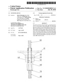
[0022]In a first embodiment of the invention, as shown in FIG. 1, there is a first tensioning device 1 for a strata support cable or tendon 80. The tensioning device 1 comprises a barrel fitting 60 and a barrel actuator 50. The barrel fitting 60 is elongate and adapted to slide over the cable or tendon. The barrel fitting 60 is in this example externally threaded. The barrel actuator 50 is movably connected to the barrel fitting 60 for longitudinal movement relative to the barrel fitting 60. The tensioning device 1 also includes locking means 40 coupled to the barrel actuator 50 for releasable engagement with the barrel fitting 60 to temporarily prevent movement of the actuator 50 relative to the barrel fitting 60. The tensioning device 1 is designed such that movement or preferably rotation of the barrel actuator 50 effects a corresponding movement of the cable or tendon for its placement in a pre-drilled cavity in the strata to be supported. This rotation also facilitates mixing of pre-installed resin or grout (not shown). Thereafter, release of the locking means 40 from the barrel fitting 60 permits longitudinal movement of the barrel actuator 50 relative to the barrel fitting 60 for tensioning of the cable or tendon within the cavity.
[0023]The locking means is a mechanical locking arrangement including a pin or rod 40 located in a corresponding hole in the barrel actuator 50. The pin or rod 40 is configured for engagement with a mating hole in the barrel fitting 60. In a preferred embodiment, the pin or rod 40 is in the form of a shear pin designed to break or fracture at a predetermined load to then permit longitudinal movement of the barrel actuator 50 relative to the barrel fitting 60.
[0024]In an alternate form, the locking means includes an adhesive, such as that sold under the LOCTITE brand, applied between the actuator 50 and the barrel fitting 60. The adhesive is designed to release at a certain torque load when the cable or tendon is retarded from rotational movement by the pre-installed grout.
[0025]The barrel actuator includes a nut 50 threaded to the barrel fitting 60. The nut 50 is threaded on its internal bore so that it engages the threaded barrel fitting 60 whereby rotation of the nut 50 effects longitudinal movement of the nut 50 relative to the barrel fitting 60. The nut 50 can be moved to a selected position for placement of the shear pin 40 in the aligned holes. The nut 50 is moved together with the barrel fitting 60 when the shear pin 40 engages the mating hole of the barrel fitting 60.
[0026]The tensioning device 1 also comprises a strata or "volcano" plate 10 having a central aperture through which the cable or tendon passes. The plate 10 has an internal rim which generally defines the central aperture and diverges away from the strata, such as a roof, rib or floor. The internal rim may have a slot which is oriented transverse to the rim.
[0027]The tensioning device 1 further comprises a bearing assembly which includes a domed washer 20 being configured to abut the strata plate 10 and permit angular installation of the cable or tendon relative to the plate 10. The bearing assembly also includes a generally flat friction washer or thrust bearing 30 and the dome washer 20 together being located between the barrel actuator 50 and the strata plate 20. The friction washer 30 functions as a barrier to prevent any sparks and ignition of combustible gases which may be generated by the friction between the barrel actuator 50 and the dome washer 20. The domed washer 20 may include a protrusion which would engage a corresponding slot in the strata plate 10 to prevent rotational movement whilst permitting tilting of the domed washer 20 relative to the plate 10 to accommodate angular installation of the cable or tendon.
[0028]The threaded barrel fitting 60 is in cross-section asymmetric along an external portion of its length. The asymmetric portion is configured to engage the similarly configured domed washer 20 to prevent rotational movement whilst allowing relative longitudinal movement. The asymmetric portion in the present embodiment is at least in part defined by a flattened longitudinal section of the threaded barrel fitting 60. The flattened section is shaped complementary to a corresponding section of the domed washer 20.
[0029]The tensioning device 1 also comprises a wedge assembly 70 having an aperture for receipt of the cable or tendon. The wedge assembly 70 has a tapered outside surface configured for engagement with a corresponding inside surface of an enlarged portion of the barrel fitting 60 to allow for clamping about the cable or tendon. In this embodiment, the wedge assembly 70 is shaped in the form of a conical frustum and is of a split design. The wedge assembly 70 of this example has three substantially identical components separated by longitudinal splits. This enables the interior of the aperture of the wedge assembly 70 to clamp firmly onto the cable or tendon. As the wedge assembly 70 is wedged longitudinally into the enlarged portion of the barrel fitting 60 it closes about the cable or tendon.
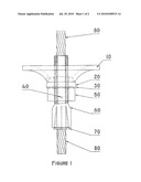
[0030]In a second embodiment of the invention, as shown in FIG. 2, there is a second tensioning device 2 for a strata support cable or tendon 800. Due to the similarities between the first and the second embodiments, only the differences between the tensioning devices are described. For ease of referencing, features which are shown in the second embodiment and are similar to those of the first embodiment are designated using similar numbering with an additional zero at the end.
[0031]A strata or "volcano" plate 100 of the second tensioning device 2 no longer has a slot, which is present in the strata plate 10 of the first tensioning device 1. Instead, an internal rim of the strata plate 100 has a roughened or soft surface.
[0032]A threaded barrel section of the second tensioning device 2 no longer has a flattened longitudinal section, which is present in the threaded barrel section of the first tensioning device 1. Instead, the threaded barrel section now has two key ways which are shaped complementary to corresponding surfaces of a dome washer 200 of the second tensioning device 2. The dome washer 200 no longer has a flattened surface, which is present in the dome washer 20 of the first tensioning device 1. In addition, the threaded barrel section 600 no longer has a mating hole 40, which is present in the first tensioning device 1.
[0033]In addition, the dome washer 200 no longer has a protrusion, which is present in the dome washer 20 of the first tensioning device 1. Instead, the dome washer 200 now has a roughened or soft surface that engages a corresponding surface of the internal rim of the strata plate 100. The roughened or soft surfaces provide a frictional force to prevent relative rotational movement between the strata plate 100 and the dome washer 200.
[0034]The second tensioning device 2 may have a friction bearing 300, instead of a friction washer or thrust bearing 30, which is present in the first tensioning device 1. the friction bearing 300 consists of two sections separated by radially oriented roller bearings which provide a low friction rotating or sliding movement between the two sections.
[0035]The second tensioning device 2 has a barrel head 650 which has all the features of the enlarged portion in the first tensioning device 1. In addition, the barrel head 650 is detachably connected to the threaded barrel section 600 to form a complete barrel fitting. A locking means or mechanical locking arrangement 400 such as a roll or shear pin is fitted to the barrel head 650 and engages a corresponding hole in a barrel actuator 500 of the second tensioning device. In line with the location of the locking means or shear pin 400, the hole in the barrel actuator or actuator nut 500 of the second tensioning device 2 is located differently to the hole in the barrel actuator 50 of the first tensioning device. A bearing assembly of the second tensioning device 2 comprises the dome washer 200 and the friction bearing 300.
[0036]During assembly of the second tensioning device 2, the actuator nut 500 is screwed onto the threaded barrel section 600 to a point where, on connecting the barrel head 650 with the threaded barrel section 600, the hole in the actuator 500 and the locking means 400 align and will engage. Once the actuator 500 is in the prescribed position, the barrel head 650 is connected with threaded barrel section 600 to form the complete barrel fitting, whilst the locking means 400 engages with the holes. The threaded section 600 may be chilled and then allowed to expand into a tight fit with the barrel head 650. In the first tensioning device 1, the hole in the nut 50 is aligned with the mating hole in the barrel fitting and the shear pin 40 is then pressed into engagement with the aligned hole and mating hole.
[0037]Operation of the tensioning devices of the alternate embodiments of the present invention are now described. To avoid duplication, reference has been made to the components of the first tensioning device only. The strata support cable or tendon is at one end passed through the strata plate 10 and the bearing assembly into the barrel fitting 60 where it is clamped for attachment by the wedge assembly 70.
[0038]A drive tool of a drill rig or other drive means such as a dolly, socket or spanner (not shown) is fitted to the actuator nut 50 for placement of the cable or tendon in a strata cavity. The cavity has using known techniques been pre-drilled and prepared with resin or grout. The cable or tendon is progressively driven into the cavity by rotation of the actuator nut 50 and barrel fitting 60 to which it is locked via the shear pin 40. Following placement of the cable or tendon and upon setting of the resin or grout, the drill rig continues to exert a rotational force to the actuator nut 50. The hardened resin retards rotation of the cable or tendon and the shear pin 40 is designed to fracture or shear at a predetermined torsional force exerted by the drive means. The actuator nut 50 rotates along the thread of the barrel fitting 60 and the nut 50 abuts the bearing assembly. The drive means is then used to further rotate the actuator nut 50 relative to the barrel fitting 60 for tensioning of the cable or tendon within the strata cavity.
[0039]The flattened section or key ways of the barrel fitting 60 engage with the corresponding surface of the domed washer 20 to prevent relative rotational movement between these components. The protrusion or roughened surface of the domed washer 20 in turn engages with the slot or roughened surface of the internal rim of the strata plate 10 to prevent relative movement between these components. This means that during tensioning of the cable or tendon it does not twist or develop a birdcaging effect at its lower portions relative to the upper section which is fixed by the resin or grout within the cavity. This embodiment of the invention can provide cable or tendon loads of up to 20 tonne. The tension loads may vary depending on the specific configuration of the tensioning device where for example a barrel fitting having a relatively fine pitched thread is capable of achieving high loads. The loads may also vary depending on the drive means used where for example a torque multiplier will provide increased tension loads.
[0040]Now that several preferred embodiments of the present invention have been described in some detail, it will be apparent to those skilled in the art that the tensioning device has at least the following advantages over the admitted prior art: [0041]i) the placement and tensioning of the strata cable or tendon can be effected in a single operation; [0042]ii) the device is relatively light and thus easier to handle than existing designs; and [0043]iii) the device lends itself to a simpler installation without for example post-grouting.
[0044]It will be appreciated by persons skilled in the art that numerous variations and/or modifications may be made to the invention as shown in the specific embodiments without departing from the spirit or scope of the invention as broadly described. For example, the locking means which engages the barrel fitting and actuator need not be limited to the mechanical or chemical types described but may take the form of a retractable latch or lock. The barrel actuator, roof plate and wedge assembly may take another form and shape. The actuator nut 50 may vary from that described and may for example be a castle-headed nut and retaining pin mechanism which eliminates the need for forming the hole in the nut. The present embodiment is, therefore, to be considered in all respects as illustrative and not restrictive.
Claims:
1. A tensioning device for a strata support cable or tendon, said device
comprising:a barrel fitting being elongate and adapted to attach to the
cable or tendon;a barrel actuator being movably connected to the barrel
fitting for longitudinal movement relative to the barrel fitting;
andlocking means operatively coupled to the barrel actuator for
releasable engagement with the barrel fitting, or vice versa, to
temporarily prevent at least longitudinal movement of said actuator
relative to the barrel fitting whereby movement of the barrel actuator
effects a corresponding movement of the barrel fitting and the cable or
tendon for its placement in a cavity and thereafter release of the
locking means from the barrel fitting, or the barrel actuator, permits
longitudinal movement of the barrel actuator relative to the barrel
fitting for tensioning of the cable or tendon within the cavity.
2. A tensioning device as defined in claim 1 wherein the barrel fitting is externally threaded and the barrel actuator includes a nut threadably attached to the barrel fitting.
3. A tensioning device as defined in claim 1 wherein the barrel fitting is of a 2-piece construction including a barrel head connected to a threaded barrel section.
4. A tensioning device as defined in claim 1 wherein the locking means is in the form of a mechanical arrangement or chemical means.
5. A tensioning device as defined in claim 4 wherein the mechanical locking arrangement includes a pin or rod slidably located in a corresponding hole in the barrel actuator and being configured for engagement with a mating recess in the barrel fitting.
6. A tensioning device as defined in claim 5 wherein the pin or rod is in the form of a shear pin designed to break or fracture at a predetermined load to then permit movement of the barrel actuator relative to the barrel fitting.
7. A tensioning device as defined in claim 2 wherein the mechanical locking arrangement includes a variation in the configuration of the external thread of the barrel fitting.
8. A tensioning device as defined in claim 1 wherein the tensioning device comprises a strata plate having a central aperture through which the cable or tendon passes.
9. A tensioning device as defined in claim 8 wherein the tensioning device comprises a bearing assembly coupled to the barrel fitting to prevent relative rotational movement, the bearing assembly being arranged to locate intermediate the barrel actuator and the strata plate for abutment with the barrel actuator on tensioning of the cable or tendon.
10. A tensioning device as defined in claim 9 wherein the bearing assembly includes a domed washer being configured to abut the strata plate and permit angular installation of the cable or tendon relative to said plate.
11. A tensioning device as defined in claim 8 wherein the bearing assembly includes a friction washer, friction bearing, or thrust bearing located between the movable actuator and the domed washer.
12. A tensioning device as defined in claim 10 wherein the domed washer includes a roughened or soft exterior surface being designed to engage a corresponding surface in the strata plate to prevent rotational movement whilst permitting tilting of the domed washer relative to the strata plate to accommodate angular installation of the cable or tendon.
13. A tensioning device as defined in claim 1 wherein the barrel fitting includes an axially oriented groove along its external surface, the groove being configured to engage a key in the domed washer to prevent rotational movement whilst allowing relative longitudinal movement.
14. A tensioning device as defined in claim 13 wherein the groove is one of a pair of grooves located on opposing sides of the barrel fitting.
15. A tensioning device as defined in claim 1 also comprising a wedge assembly having an aperture for receipt of the cable or tendon, the wedge assembly having a tapered outside surface configured for engagement with a corresponding inside surface of the barrel fitting for clamping about the cable or tendon.
16. A tensioning device as defined in claim 15 wherein the wedge assembly is shaped in the form of a conical frustum and is of a split design.
17. A tensioning device as defined in claim 1 wherein the cavity in which the cable or tendon is placed is a pre-drilled cavity.
18. A tensioning device as defined in claim 1 wherein the strata support cable or tendon includes wire rope.
19. A tensioning device for a strata support cable or tendon, said device comprising:a barrel fitting being elongate and adapted to attach to the cable or tendon;a barrel actuator being movably connected to the barrel fitting for longitudinal movement relative to the barrel fitting; anda locking portion arranged to temporarily prevent at least longitudinal movement of said actuator relative to the barrel fitting whereby movement of the barrel actuator effects a corresponding movement of the barrel fitting and the cable or tendon for its placement in a cavity, and thereafter release of the locking portion permits longitudinal movement of the barrel actuator relative to the barrel fitting for tensioning of the cable or tendon within the cavity.
20. A tensioning device as defined in claim 19 wherein the barrel fitting is externally threaded and the barrel actuator includes a nut threadably attached to the barrel fitting.
21. A tensioning device as defined in claim 19 wherein the locking portion is constructed to release upon application of a predetermined load to then permit movement of the barrel actuator relative to the barrel fitting.
22. A tensioning device as defined in claim 19 wherein the tensioning device comprises a strata plate having a central aperture through which the cable or tendon passes, and a bearing assembly coupled to the barrel fitting to prevent relative rotational movement, the bearing assembly being arranged to locate intermediate the barrel actuator and the strata plate for abutment with the barrel actuator on tensioning of the cable or tendon.
23. A tensioning device as defined in claim 19 also comprising a wedge assembly having an aperture for receipt of the cable or tendon, the wedge assembly having a tapered outside surface configured for engagement with a corresponding inside surface of the barrel fitting for clamping about the cable or tendon.
Description:
FIELD OF THE INVENTION
[0001]The present invention relates broadly to a tensioning device for a strata support cable or tendon.
BACKGROUND OF THE INVENTION
[0002]In underground mining and strata control, bolting is generally recognised as the primary support system. Bolting involves grouting of a rock bolt within a bolt hole formed in the strata of an underground mine. The bolt is tensioned so that the strata surrounding the bolthole is held in compression. This technique has been extended to cables or tendons where a barrel and wedge fitting is attached to the cable and is tensioned using hydraulically actuated equipment. These prior art arrangements suffer from at least the following drawbacks: [0003]i) the tensioning of cables and tendons is time consuming because they comprise multiple stages and thus are expensive operations; [0004]ii) the cables and tendons require relatively large pulling rigs to achieve high tension loads; and [0005]iii) existing designs are large and very heavy to handle creating additional occupational health and safety hazards.
SUMMARY OF THE INVENTION
[0006]According to the present invention there is provided a tensioning device for a strata support cable or tendon, said device comprising: [0007]a barrel fitting being elongate and adapted to attach to the cable or tendon; [0008]a barrel actuator being movably connected to the barrel fitting for longitudinal movement relative to the barrel fitting; and [0009]locking means operatively coupled to the barrel actuator for releasable engagement with the barrel fitting, or vice versa, to temporarily prevent at least longitudinal movement of said actuator relative to the barrel fitting whereby movement of the barrel actuator effects a corresponding movement of the barrel fitting and the cable or tendon for its placement in a cavity and thereafter release of the locking means from the barrel fitting, or the barrel actuator, permits longitudinal movement of the barrel actuator relative to the barrel fitting for tensioning of the cable or tendon within the cavity.
[0010]Preferably the barrel fitting is externally threaded and the barrel actuator includes a nut threadably attached to the barrel fitting. In another configuration the barrel fitting is of a 2-piece construction including a barrel head connected to a threaded barrel section.
[0011]Preferably the locking means is in the form of a mechanical arrangement or chemical means.
[0012]Preferably the mechanical locking arrangement includes a pin or rod slidably located in a corresponding hole in the barrel actuator and being configured for engagement with a mating recess in the barrel fitting. More preferably the pin or rod is in the form of a shear pin designed to break or fracture at a predetermined load to then permit movement of the barrel actuator relative to the barrel fitting. Alternatively the mechanical locking arrangement includes a variation in the configuration of the external thread of the barrel fitting.
[0013]Preferably the tensioning device also comprises a strata plate having a central aperture through which the cable or tendon passes. In one example the strata plate is in the form of a volcano plate or dome plate.
[0014]Preferably the tensioning device further comprises a bearing assembly coupled to the barrel fitting to prevent relative rotational movement, the bearing assembly being arranged to locate intermediate the barrel actuator and the strata plate for abutment with the barrel actuator on tensioning of the cable or tendon. More preferably the bearing assembly includes a domed washer being configured to abut the strata plate and permit angular installation of the cable or tendon relative to said plate. Even more preferably the bearing assembly also includes a friction washer, friction bearing, or thrust bearing located between the movable actuator and the domed washer. Still more preferably the domed washer includes a roughened or soft exterior surface being designed to engage a corresponding surface in the strata plate to prevent rotational movement whilst permitting tilting of the domed washer relative to the strata plate to accommodate angular installation of the cable or tendon.
[0015]Preferably the threaded barrel fitting includes an axially oriented groove along its external surface, the groove being configured to engage a key in the domed washer to prevent rotational movement whilst allowing relative longitudinal movement. More preferably the groove is one of a pair of grooves located on opposing sides of the barrel fitting.
[0016]Preferably the tensioning device also comprises a wedge assembly having an aperture for receipt of the cable or tendon, the wedge assembly having a tapered outside surface configured for engagement with a corresponding inside surface of the barrel fitting for clamping about the cable or tendon. More preferably the wedge assembly is shaped in the form of a conical frustum and is of a split design.
[0017]Generally the cavity in which the cable or tendon is placed is a pre-drilled cavity.
[0018]The strata support cable or tendon is to be understood to include wire rope or strand.
BRIEF DESCRIPTION OF THE DRAWINGS
[0019]In order to achieve a better understanding of the nature of the present invention a preferred embodiment of a tensioning device for a strata support cable or tendon will now be described, by way of example only, with reference to the accompanying drawings in which:
[0020]FIG. 1 is a side view of a tensioning device of a first embodiment of the present invention; and
[0021]FIG. 2 is a side view of a tensioning device of a second embodiment of the present invention;
DETAILED DESCRIPTION OF THE INVENTION
[0022]In a first embodiment of the invention, as shown in FIG. 1, there is a first tensioning device 1 for a strata support cable or tendon 80. The tensioning device 1 comprises a barrel fitting 60 and a barrel actuator 50. The barrel fitting 60 is elongate and adapted to slide over the cable or tendon. The barrel fitting 60 is in this example externally threaded. The barrel actuator 50 is movably connected to the barrel fitting 60 for longitudinal movement relative to the barrel fitting 60. The tensioning device 1 also includes locking means 40 coupled to the barrel actuator 50 for releasable engagement with the barrel fitting 60 to temporarily prevent movement of the actuator 50 relative to the barrel fitting 60. The tensioning device 1 is designed such that movement or preferably rotation of the barrel actuator 50 effects a corresponding movement of the cable or tendon for its placement in a pre-drilled cavity in the strata to be supported. This rotation also facilitates mixing of pre-installed resin or grout (not shown). Thereafter, release of the locking means 40 from the barrel fitting 60 permits longitudinal movement of the barrel actuator 50 relative to the barrel fitting 60 for tensioning of the cable or tendon within the cavity.
[0023]The locking means is a mechanical locking arrangement including a pin or rod 40 located in a corresponding hole in the barrel actuator 50. The pin or rod 40 is configured for engagement with a mating hole in the barrel fitting 60. In a preferred embodiment, the pin or rod 40 is in the form of a shear pin designed to break or fracture at a predetermined load to then permit longitudinal movement of the barrel actuator 50 relative to the barrel fitting 60.
[0024]In an alternate form, the locking means includes an adhesive, such as that sold under the LOCTITE brand, applied between the actuator 50 and the barrel fitting 60. The adhesive is designed to release at a certain torque load when the cable or tendon is retarded from rotational movement by the pre-installed grout.
[0025]The barrel actuator includes a nut 50 threaded to the barrel fitting 60. The nut 50 is threaded on its internal bore so that it engages the threaded barrel fitting 60 whereby rotation of the nut 50 effects longitudinal movement of the nut 50 relative to the barrel fitting 60. The nut 50 can be moved to a selected position for placement of the shear pin 40 in the aligned holes. The nut 50 is moved together with the barrel fitting 60 when the shear pin 40 engages the mating hole of the barrel fitting 60.
[0026]The tensioning device 1 also comprises a strata or "volcano" plate 10 having a central aperture through which the cable or tendon passes. The plate 10 has an internal rim which generally defines the central aperture and diverges away from the strata, such as a roof, rib or floor. The internal rim may have a slot which is oriented transverse to the rim.
[0027]The tensioning device 1 further comprises a bearing assembly which includes a domed washer 20 being configured to abut the strata plate 10 and permit angular installation of the cable or tendon relative to the plate 10. The bearing assembly also includes a generally flat friction washer or thrust bearing 30 and the dome washer 20 together being located between the barrel actuator 50 and the strata plate 20. The friction washer 30 functions as a barrier to prevent any sparks and ignition of combustible gases which may be generated by the friction between the barrel actuator 50 and the dome washer 20. The domed washer 20 may include a protrusion which would engage a corresponding slot in the strata plate 10 to prevent rotational movement whilst permitting tilting of the domed washer 20 relative to the plate 10 to accommodate angular installation of the cable or tendon.
[0028]The threaded barrel fitting 60 is in cross-section asymmetric along an external portion of its length. The asymmetric portion is configured to engage the similarly configured domed washer 20 to prevent rotational movement whilst allowing relative longitudinal movement. The asymmetric portion in the present embodiment is at least in part defined by a flattened longitudinal section of the threaded barrel fitting 60. The flattened section is shaped complementary to a corresponding section of the domed washer 20.
[0029]The tensioning device 1 also comprises a wedge assembly 70 having an aperture for receipt of the cable or tendon. The wedge assembly 70 has a tapered outside surface configured for engagement with a corresponding inside surface of an enlarged portion of the barrel fitting 60 to allow for clamping about the cable or tendon. In this embodiment, the wedge assembly 70 is shaped in the form of a conical frustum and is of a split design. The wedge assembly 70 of this example has three substantially identical components separated by longitudinal splits. This enables the interior of the aperture of the wedge assembly 70 to clamp firmly onto the cable or tendon. As the wedge assembly 70 is wedged longitudinally into the enlarged portion of the barrel fitting 60 it closes about the cable or tendon.
[0030]In a second embodiment of the invention, as shown in FIG. 2, there is a second tensioning device 2 for a strata support cable or tendon 800. Due to the similarities between the first and the second embodiments, only the differences between the tensioning devices are described. For ease of referencing, features which are shown in the second embodiment and are similar to those of the first embodiment are designated using similar numbering with an additional zero at the end.
[0031]A strata or "volcano" plate 100 of the second tensioning device 2 no longer has a slot, which is present in the strata plate 10 of the first tensioning device 1. Instead, an internal rim of the strata plate 100 has a roughened or soft surface.
[0032]A threaded barrel section of the second tensioning device 2 no longer has a flattened longitudinal section, which is present in the threaded barrel section of the first tensioning device 1. Instead, the threaded barrel section now has two key ways which are shaped complementary to corresponding surfaces of a dome washer 200 of the second tensioning device 2. The dome washer 200 no longer has a flattened surface, which is present in the dome washer 20 of the first tensioning device 1. In addition, the threaded barrel section 600 no longer has a mating hole 40, which is present in the first tensioning device 1.
[0033]In addition, the dome washer 200 no longer has a protrusion, which is present in the dome washer 20 of the first tensioning device 1. Instead, the dome washer 200 now has a roughened or soft surface that engages a corresponding surface of the internal rim of the strata plate 100. The roughened or soft surfaces provide a frictional force to prevent relative rotational movement between the strata plate 100 and the dome washer 200.
[0034]The second tensioning device 2 may have a friction bearing 300, instead of a friction washer or thrust bearing 30, which is present in the first tensioning device 1. the friction bearing 300 consists of two sections separated by radially oriented roller bearings which provide a low friction rotating or sliding movement between the two sections.
[0035]The second tensioning device 2 has a barrel head 650 which has all the features of the enlarged portion in the first tensioning device 1. In addition, the barrel head 650 is detachably connected to the threaded barrel section 600 to form a complete barrel fitting. A locking means or mechanical locking arrangement 400 such as a roll or shear pin is fitted to the barrel head 650 and engages a corresponding hole in a barrel actuator 500 of the second tensioning device. In line with the location of the locking means or shear pin 400, the hole in the barrel actuator or actuator nut 500 of the second tensioning device 2 is located differently to the hole in the barrel actuator 50 of the first tensioning device. A bearing assembly of the second tensioning device 2 comprises the dome washer 200 and the friction bearing 300.
[0036]During assembly of the second tensioning device 2, the actuator nut 500 is screwed onto the threaded barrel section 600 to a point where, on connecting the barrel head 650 with the threaded barrel section 600, the hole in the actuator 500 and the locking means 400 align and will engage. Once the actuator 500 is in the prescribed position, the barrel head 650 is connected with threaded barrel section 600 to form the complete barrel fitting, whilst the locking means 400 engages with the holes. The threaded section 600 may be chilled and then allowed to expand into a tight fit with the barrel head 650. In the first tensioning device 1, the hole in the nut 50 is aligned with the mating hole in the barrel fitting and the shear pin 40 is then pressed into engagement with the aligned hole and mating hole.
[0037]Operation of the tensioning devices of the alternate embodiments of the present invention are now described. To avoid duplication, reference has been made to the components of the first tensioning device only. The strata support cable or tendon is at one end passed through the strata plate 10 and the bearing assembly into the barrel fitting 60 where it is clamped for attachment by the wedge assembly 70.
[0038]A drive tool of a drill rig or other drive means such as a dolly, socket or spanner (not shown) is fitted to the actuator nut 50 for placement of the cable or tendon in a strata cavity. The cavity has using known techniques been pre-drilled and prepared with resin or grout. The cable or tendon is progressively driven into the cavity by rotation of the actuator nut 50 and barrel fitting 60 to which it is locked via the shear pin 40. Following placement of the cable or tendon and upon setting of the resin or grout, the drill rig continues to exert a rotational force to the actuator nut 50. The hardened resin retards rotation of the cable or tendon and the shear pin 40 is designed to fracture or shear at a predetermined torsional force exerted by the drive means. The actuator nut 50 rotates along the thread of the barrel fitting 60 and the nut 50 abuts the bearing assembly. The drive means is then used to further rotate the actuator nut 50 relative to the barrel fitting 60 for tensioning of the cable or tendon within the strata cavity.
[0039]The flattened section or key ways of the barrel fitting 60 engage with the corresponding surface of the domed washer 20 to prevent relative rotational movement between these components. The protrusion or roughened surface of the domed washer 20 in turn engages with the slot or roughened surface of the internal rim of the strata plate 10 to prevent relative movement between these components. This means that during tensioning of the cable or tendon it does not twist or develop a birdcaging effect at its lower portions relative to the upper section which is fixed by the resin or grout within the cavity. This embodiment of the invention can provide cable or tendon loads of up to 20 tonne. The tension loads may vary depending on the specific configuration of the tensioning device where for example a barrel fitting having a relatively fine pitched thread is capable of achieving high loads. The loads may also vary depending on the drive means used where for example a torque multiplier will provide increased tension loads.
[0040]Now that several preferred embodiments of the present invention have been described in some detail, it will be apparent to those skilled in the art that the tensioning device has at least the following advantages over the admitted prior art: [0041]i) the placement and tensioning of the strata cable or tendon can be effected in a single operation; [0042]ii) the device is relatively light and thus easier to handle than existing designs; and [0043]iii) the device lends itself to a simpler installation without for example post-grouting.
[0044]It will be appreciated by persons skilled in the art that numerous variations and/or modifications may be made to the invention as shown in the specific embodiments without departing from the spirit or scope of the invention as broadly described. For example, the locking means which engages the barrel fitting and actuator need not be limited to the mechanical or chemical types described but may take the form of a retractable latch or lock. The barrel actuator, roof plate and wedge assembly may take another form and shape. The actuator nut 50 may vary from that described and may for example be a castle-headed nut and retaining pin mechanism which eliminates the need for forming the hole in the nut. The present embodiment is, therefore, to be considered in all respects as illustrative and not restrictive.
User Contributions:
Comment about this patent or add new information about this topic:
Images included with this patent application:
 |  |
 |
| Similar patent applications: | |
| Date | Title |
|---|---|
| 2008-09-11 | Trench shoring extraction device |
| 2008-10-16 | Pipeline assembly comprising an anchoring device |
| 2009-11-05 | Systems and methods for selection of suppression devices |
| 2010-02-25 | Riser tensioner restraint device |
| 2012-05-03 | Pipeline assembly comprising an anchoring device |
| New patent applications in this class: | |
| Date | Title |
|---|---|
| 2018-01-25 | Slotted tubular anchor |
| 2016-06-30 | Friction bolt assembly |
| 2016-06-30 | Self-undercut anchor system |
| 2016-06-16 | Yieldable rock anchor |
| 2016-05-19 | Anchoring and anti-clogging drill rod for coal mine floor |
| Top Inventors for class "Hydraulic and earth engineering" | |
| Rank | Inventor's name |
|---|---|
| 1 | Joop Roodenburg |
| 2 | Thomas P. Taylor |
| 3 | Michael Tjader |
| 4 | Keith K. Millheim |
| 5 | John G. Oldsen |