Patent application title: Wind resistant hedgerow
Inventors:
Christopher Hatton (Bradford, GB)
IPC8 Class: AE04H1702FI
USPC Class:
256 19
Class name: Fences earth, stone, plastic, and wooden
Publication date: 2010-07-29
Patent application number: 20100187490
Inventors list |
Agents list |
Assignees list |
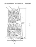
List by place |
Classification tree browser |
Top 100 Inventors |
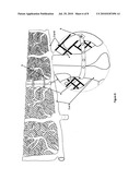
Top 100 Agents |
Top 100 Assignees |
Usenet FAQ Index |
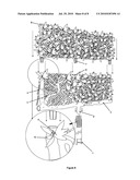
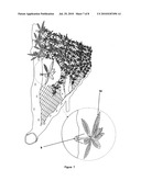
Documents |
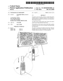
Other FAQs |
Patent application title: Wind resistant hedgerow
Inventors:
Christopher Hatton
Agents:
Mr. Christopher Hatton
Assignees:
Origin: BRADFORD, WEST YORKSHIRE, GB
IPC8 Class: AE04H1702FI
USPC Class:
256 19
Publication date: 07/29/2010
Patent application number: 20100187490
Abstract:
An exterior screen for safety, security, soundproofing and/or aesthetic
purposes. Substantial amount of costs and time is apportioned to the
installation, permanency and maintenance of conventional screens.
An impact driven sprung anchor point, allows the exterior screen to pivot
back and forth when forced.
The production of the exterior screen would utilise modular construction
from non-corrosive materials reducing damage and replacement.
The option of using the pre-drilled locating holes within the paneling
structure allows attachments for safety, security, soundproofing and
aesthetics to be interchangeable.Claims:
1. Exterior hedgerow panels that are modular in manufacture and consisting
of integral connection prongs and compatible receiving pockets for the
secure attachment of said panels.
2. Exterior hedgerow panels, as claim 1, consisting of an integral strap and integral pin, used for the binding of said panels when adjoined laterally, to prevent twisting.
3. Exterior hedgerow components will be manufactured from re-cycled plastic material, ie, panels, socket, mesh, straps, pins, foliage, security, sound-proofing and decorative accessories.
4. Exterior hedgerow panels, as claim 1, including pre-drilled locating holes for the attachment of variable security, sound-proofing, and/or decorative components as claim 3.
5. Exterior hedgerow panels, as in claim 1, consisting of an integral pre-moulded mesh, to act as a support for the protection of variable attachments as in claim 3 and claim 4.
6. A sprung anchor system constructed of stainless steel, consisting essentially of an hollow tube, manufactured in stainless steel, with the top re-bored to a given depth, to accept a pre-defined spring. This said spring would rest within the hollow tube at this given depth and secured via a grub screw utilising the pre-drilled locating hole. The opposing end of the said hollow tube would be mechanically lathed to produce an internal cutting edge, ensuring that the ground area to be penetrated was incorporated within the tube rather than displaced.
7. Exterior hedgerow panels, as in claim 1, which include a pre-formed bottom socket for insertion into the sprung anchor system as claim 6, rendering the said panels to be flexible in their movement.
Description:
TECHNICAL FIELD OF THE INVENTION
[0001]This invention relates to fencing and exterior screening products, and more particularly, to the modular, multi-dimensional, decorative and flexible aspects.
BACKGROUND OF THE INVENTION
[0002]When exterior fencing or screening is required for safety, security, sound-proofing and/or aesthetics, a substantial amount of cost and labour is apportioned to the installation, permanency and maintenance of the product.
[0003]Conventional options are man made or naturally grown and are reliant on site type and condition. The maintenance logistics of these said products is dependant on the repair, replacement, weather variants and control of natural growth.
[0004]The invention proposes the use of a stainless steel spring loaded anchor system, adaptable for variations in site types. The inventions modular components are to be manufactured from non-corrosive recyclable material. The stainless steel sprung anchor system would support a modular component panel and accessories manufactured of non-corrosive, recyclable material. The said panel system would be interchangeable and extendable depending on required dimensions. Once the said panel system is assembled and attached to the said anchor system, it would be flexible on its sprung pivot, allowing the whole unit to return to its installed state after forced movement.
[0005]Allowances fabricated within the panel system to accept decorative attached accessories would enhance the inventions sound proofing and visual screening qualities.
[0006]The said anchor system would be installed via an impact based method of driving it beneath ground level. The anchor system can be amended to incorporate wall or float fixed methods of installation.
SUMMARY OF THE INVENTION
[0007]First aspect of the invention is to provide a cost effective alternative to prior art based products, whilst maintaining its ease of use.
[0008]Secondly, with its modular construction the invention increases its multi-dimensionality.
[0009]The third aspect of the invention allows for the attachment of decorative, sound proofing and screening accessories to be utilised.
[0010]Fourth aspect is its use of non-corrosive materials in its manufacture, thereby reducing its component need for repair or replacement. Moving on to the fifth aspect is its sprung anchor system, allowing the whole structure to flex when forced and then return to its installed state, thereby imitating a naturally grown hedgerow.
[0011]In accordance with the above aspects, the invention would take on the appearance and characteristics of a naturally grown hedgerow, without the maintenance logistics. The sprung anchor system, when driven into the ground, would emulate the natural root.
BRIEF DESCRIPTION OF THE DRAWINGS FOR THE INVENTION
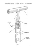
[0012]FIG. 1 shows the ground fixed stainless steel Sprung Anchor System 1.
[0013]FIG. 2 shows an injection moulded Modular Base Panel 3, incorporating a fabricated Bottom Socket 2, for receiving the Sprung Anchor System 1. Also shown here are the integrated Panel Straps 4, the Panel Strap Pins 5, the Connection Prong Pockets 6 and the pre-drilled Panel Foliage Locating Holes 9.
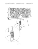
[0014]In FIG. 3, an example of the fitting process for the attachment between the Modular Base Panel 3, the Bottom Socket 2 and the Sprung Anchor System 1, is shown. When the Sprung Anchor System 1 is impacted into the ground, the Modular Base Panel 3 is attached and secured via a grub screw.
[0015]FIG. 4 shows the Modular Extension Panel 8 with integrated Connection Prongs 7 and Connection Prong Pockets 6.
[0016]In FIG. 5 the fitting process example between the Modular Extension Panel 8 and the Modular Base Panel 3 is shown, utilising the Connection Prongs 7 and the Connection Prong Pockets 6.
[0017]FIG. 6 shows an example of the fitting process for securing two Modular Base Panels 3 together, or two Modular Extension Panels 8, using the Panel Straps 4 locating to the Panel Strap Pins 5.
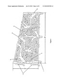
[0018]FIG. 7 shows an example of the Panel Foliage 10 attachment process to the Modular Panels 3,8 using the pre-drilled Panel Foliage Locating Holes 9.
[0019]FIG. 8 shows the Hedgerow unit assembly to be used by the Abstract.
DETAILED DESCRIPTION OF THE INVENTION
[0020]The invention will now be described by way of example and drawing reference.
[0021]Referring to FIG. 1 showing the Sprung Anchor System 1, incorporating a stainless steel spring mechanism attached to an hollow stainless steel tube by way of grub screw. The hollow tube is mechanically bored to produce an inner ridge, at a pre-defined depth, to prevent the spring from over traveling. The alternative end is then lathed and cut to produce an internal cutting edge for impact driving into the ground surface.
[0022]The internal diameter of the spring is compatible with the external diameter of the Bottom Socket 2, which is integral to the Modular Base Panel 3.
[0023]After the Sprung Anchor System 1 is driven into the ground, the Bottom Socket 2 is inserted into the spring and secured using grub screw fixing as in FIG. 3.
[0024]When the Sprung Anchor System 1 and Modular Base Panel 3 are installed, we see in FIG. 4 the Modular Extension Panel 8 incorporating pre-fabricated Connection Prongs 7, ready to be attached using the Connection Panel Pockets 6 seen in FIG. 5.
[0025]Should it be necessary for additional Modular Panels to be connected laterally, the process is shown in FIG. 6, using the aesthetic Panel Strapping 4 and corresponding Panel Strapping Pins 5. This process binds the Modular Panels to prevent twisting.
[0026]If there is a requirement for decorative, sound proofing or screening features, then the provision of pre-drilled Locating Holes 9 can be utilised for the attachment of Panel Foliage 10 as in FIG. 7.
[0027]This Panel Foliage 10 is not limiting in its volume and appearance and should be determined by customer preference.
User Contributions:
comments("1"); ?> comment_form("1"); ?>Inventors list |
Agents list |
Assignees list |
List by place |
Classification tree browser |
Top 100 Inventors |
Top 100 Agents |
Top 100 Assignees |
Usenet FAQ Index |
Documents |
Other FAQs |
User Contributions:
Comment about this patent or add new information about this topic:
| People who visited this patent also read: | |
| Patent application number | Title |
|---|---|
| 20100187004 | LEAD PIN FOR MOUNTING SEMICONDUCTOR AND PRINTED WIRING BOARD |
| 20100186990 | High Voltage Electric Submersible Pump Cable |
| 20100186984 | Integral wind turbine wiring enclosure cabinet |
| 20100186978 | Rotary impact tool |
| 20100186973 | Fire Sprinkler with Cutoff Valve, Tamper-Resistant Features and Status Indicator |
Images included with this patent application:
 |  |
 |  |
 |  |
 |  |
| Similar patent applications: | |
| Date | Title |
|---|---|
| 2009-02-05 | High impact resistant barrier/fence |
| 2009-07-16 | Fencing for residential and commercial use |
| New patent applications in this class: | |
| Date | Title |
|---|---|
| 2016-06-23 | Mesh fence material and method for making thereof |
| 2015-01-22 | Barrier fence assembly |
| 2014-11-06 | Support for barrier fencing |
| 2014-07-24 | Retrofit fence panels |
| 2014-07-24 | Fence system with variable rail reinforcement |
| Top Inventors for class "Fences" | |
| Rank | Inventor's name |
|---|---|
| 1 | Dallas James |
| 2 | Robert E. Platt |
| 3 | Gordon Duffy |
| 4 | Jason Duffy |
| 5 | Matthew Carlyle Sherstad |