Patent application title: STRUCTURE OF SHOES UPPERS, A MANUFACTURING METHOD OF SHOES AND A STRUCTURE OF SHOES
Inventors:
Byung Hun Lee (Busan, KR)
IPC8 Class: AA43B706FI
USPC Class:
36 3 B
Class name: Boots and shoes ventilated soles
Publication date: 2010-07-29
Patent application number: 20100186263
ates to a shoe, a shoe upper which maintains a
stable shoe form and can be attached to a sole assembly lacking part of a
midsole, a method of manufacturing the shoe, and a shoe capable of
improving a wearer's health. The shoe upper, attached to the sole
assembly so as to constitute a shoe, has a constriction lace which
surrounds a first part of an opening thereof, which directs the sole
assembly and a coupling member for coupling the constriction lace to the
shoe upper in a manner such that the constriction lace can constrict or
loosen the opening.Claims:
1. A shoe upper which constitutes a shoe by being attached to a sole
assembly, comprising:a constriction lace provided at a first part of an
opening of the shoe upper which directly contacts the sole assembly; anda
coupling member for coupling the constriction lace to the shoe upper in a
manner such that the constriction lace constricts or loosens the first
part of the opening of the shoe upper.
2. The shoe upper according to claim 1, wherein the coupling member is a string sewn along a boundary of the first part of the opening of the shoe upper.
3. The shoe upper according to claim 1, further comprising a midsole attached to a second part of the opening at a position at which the constriction lace is not provided.
4. The shoe upper according to claim 3, wherein a flexible member is provided in the first part of the opening of the shoe upper, which is surrounded by the constriction lace.
5. A method of manufacturing a shoe which is manufactured by attaching a shoe upper having a constriction lace surrounding a first part of an opening of the shoe upper, which directly contacts a sole assembly, and a coupling member for coupling the shoe lace to the first part of the shoe upper so that the constriction lace constricts or loosens the first part of the opening, to the sole assembly, comprising:setting up a basic shoe structure by placing a shoe last into the shoe upper and then constricting the first part of the opening by pulling the constriction lace so that the opening comes to have a form corresponding to a form of the shoe last; processing the constriction lace so that a knot of the constriction lace does not come untied; andcompleting the shoe in which the sole assembly is visible through the opening of the shoe upper by attaching the shoe upper to the sole assembly.
6. The method according to claim 5, wherein the coupling member is a string sewn to a boundary of the first part of the opening of the shoe upper in a manner of surrounding the constriction lace.
7. The method according to claim 5, wherein the processing is performed by constricting the opening by pulling the constriction lace, forming a knot, and pounding the knot to be flat.
8. The method according to claim 7, wherein the opening is constricted after a midsole is attached to a second part of the shoe upper, the second part not being surrounded by the constriction lace.
9. A shoe having a shoe upper with an opening which is near a sole assembly and the sole assembly being visible inside the shoe, thanks to a structure in which the shoe upper is attached to the sole assembly after a basic shoe structure is set up by constricting part of the opening of the shoe upper using a constriction lace, wherein the sole assembly has a cushion which is thickest in a middle portion thereof and becomes thicker as it goes to a front end and a back end thereof, respectively, and wherein the cushion is pressed at a front portion and a back portion by weight of a wearer, so that the overall slope of the sole assembly is changed when the wearer wears the shoe.
10. The shoe according to claim 9, wherein the sole assembly includes:an upper midsole which is thickest in a middle portion thereof and becomes thinner as it goes to a front end and a back end, respectively, thereof;a lower midsole which is thinnest in a middle portion thereof and becomes thicker as it goes to a front end and a back end, respectively, thereof; andan outsole having abrasion resistance and attached to a lower surface of the lower midsole.
11. The shoe according to claim in wherein pumping chambers are provided in a front portion and a back portion of the shoe by combining the upper midsole and the lower midsole, an air circulation passage is provided between the pumping chambers, and at least one air discharge hole is provided to the upper midsole in order to discharge air from the pumping chambers into the shoe upper.
12. The shoe according to claim 11, wherein the air circulation path is constituted by a connection groove formed between a front pumping chamber and a back pumping chamber provided to the upper midsole and a connection groove formed between a front pumping chamber and a back pumping chamber provided to the lower midsole.
13. The shoe according to claim 11, wherein a shock absorbing member is provided to the pumping chamber in the lower midsole in order to absorb shocks attributable to pumping operation.
14. The shoe upper according to claim 2, further comprising a midsole attached to a second part of the opening at a position at which the constriction lace is not provided.
15. The method according to claim 6, wherein the processing is performed by constricting the opening by pulling the constriction lace, forming a knot, and pounding the knot to be flat.Description:
TECHNICAL FIELD
[0001]The present invention relates to a shoe, and more particularly to a shoe upper which can maintain a stable shoe structure and can be attached to a sole assembly lacking part of a midsole, a method of manufacturing a shoe, and a shoe having a function of improving the wearer's health.
BACKGROUND ART
[0002]Shoes absorb shocks and protect wearer's feet when wearers move. A shoe is generally manufactured by first setting up the basic shoe structure by bonding the midsole to the entire lower end of the shoe upper and then by bonding the midsole to the outsole.
[0003]With the recent increased interest in health, techniques for a variety of shoes which can positively affect wearer's health have been suggested. Among the techniques, a technique in which particular functions are provided to the outsole of a shoe and the functions are performed when a wearer walks while wearing the shoe is popular. In this technique, further improvement is demanded in order to make the functions provided to the outsole be more effectively performed by making the sole of a wearer's foot directly contact the outsole of the shoe instead of contacting the midsole.
[0004]Korean Patent 627728, the application for which was filed in 2006 and which has now been granted, discloses a known technique in which the outsole is divided into an upper layer and a lower layer. Further, part of the outsole, made of a cushiony material, protrudes upward into the shoe through the opening formed in the midsole and the upper layer of the outsole, so that the cushion of the outsole comes into direct contact with the heel of a wearer. Thanks to this structure, the wearer can feel cushioned and comfortable when the wearer walks while wearing the shoe.
[0005]Until now, as for all shoes, the basic shoe structure is set up in a way that the shoe upper is combined with the outsole in the presence of the midsole therebetween. Accordingly, direct contact between the sole of a wearer's foot and the outsole of the shoe can only be accomplished using a midsole having an aperture through which part of the outsole is visible.
[0006]The technique of using the midsole with an aperture is disadvantageous in that the aperture size is not sufficiently large because the area of the midsole in which the aperture can be formed is limited. That is, the aperture can be provided only in a portion of the midsole other than a bonding region in which the shoe upper and the midsole are bonded to each other.
[0007]Accordingly, the sole of a wearer's foot cannot sufficiently contact the outsole of a shoe, so that the functions imparted to the outsole cannot be sufficiently performed when the wearer walks.
DISCLOSURE OF INVENTION
Technical Problem
[0008]The object of the invention is to provide a shoe upper capable of forming a basic shoe structure, which can be attached to a sole assembly lacking part of a midsole, and a method of manufacturing a shoe using the shoe upper.
[0009]Another object of the invention are to provide a shoe having a function of positively affecting a wearer's health thanks to the structure in which the sole of the wearer's foot can sufficiently contact the sole assembly of the shoe due to the shoe upper and the manufacturing method.
Technical Solution
[0010]In order to solve the various problems encountered in the known art, and in order to achieve the above described advantageous effects and features, in accordance with one aspect of the invention, there is provided a shoe upper which constitutes a shoe by being attached to a sole assembly, including a constriction lace provided at a first part of an opening of the shoe upper which directly contacts the sole assembly, and a coupling member for coupling the constriction lace to the shoe upper in a manner such that the constriction lace constricts or loosens the first part of the opening of the shoe upper.
[0011]In the shoe upper, it is preferable that the coupling member be a string sewn along the first part of the opening and that the shoe upper further comprise a midsole attached to a second part of the opening at a position in which the constriction lace is not provided.
[0012]In the shoe upper, it is preferable that the midsole have a flexible member at a position corresponding to the first part of the opening, which is surrounded by the constriction lace.
[0013]According to another aspect of the invention, there is provided a method of manufacturing a shoe including a step of setting up a basic shoe structure corresponding to a form of a shoe last using a shoe upper by placing the shoe last into the shoe upper and then constricting an opening of a lower open end of the shoe upper by pulling the constriction lace, processing the constriction lace so that a knot of the constriction lace does not come to be untied, and completing the shoe, the sole assembly of which protrudes upward through the opening in the shoe upper, by attaching the shoe upper to the sole assembly.
[0014]In the method, it is preferable that the coupling member be a string sewn to a boundary of the opening of the shoe upper in a manner of surrounding the constriction lace and that the processing be performed by constricting the opening by pulling the constriction lace, forming a knot, and making the knot flat.
[0015]In the method, it is preferable that the opening be constricted after a midsole is attached to part of the shoe upper, the part not being surrounded by the constriction lace.
[0016]According to a further aspect of the invention, there is provided a shoe constituted by attaching a shoe upper to a sole assembly, in which the sole assembly is visible inside the shoe, wherein the sole assembly has a cushion which is thickest in the middle portion thereof and becomes thicker going to the front end and the back end thereof, respectively, and wherein the cushion is pressed at the front portion and the back portion by the weight of a wearer, so that the overall slope of the sole assembly is changed when the wearer wears the shoe.
[0017]In the shoe, it is preferable that the sole assembly include an upper midsole which is thickest in the middle portion thereof and becomes thinner going to the front end and the back end thereof, a lower midsole which is thinnest in the middle portion thereof and becomes thicker going to the front end and the back end thereof, and an outsole having abrasion resistance and being attached to the lower surface of the lower midsole, in which pumping chambers are provided in the front portion and the back portion of the shoe by combining the upper midsole and the lower midsole, an air circulation passage is provided between the pumping chambers, and at least one air discharge hole is provided to the upper midsole in order to discharge out air from the pumping chambers into the shoe upper.
[0018]In the shoe, it is preferable that the air circulation path be constituted by a connection groove between a front pumping chamber and a back pumping chamber provided to the upper midsole and a connection groove between a front pumping chamber and a back pumping chamber provided to the lower midsole.
BRIEF DESCRIPTION OF THE DRAWINGS
[0019]FIG. 1 is an exploded perspective view illustrating a known show structure of a shoe;
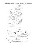
[0020]FIG. 2 is an exploded perspective view illustrating the shoe upper and the midsole of a shoe according to one embodiment of the invention;
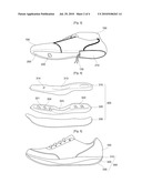
[0021]FIG. 3 is a perspective view illustrating the shoe upper and the midsole combined with each other according to one embodiment of the invention;
[0022]FIG. 4 is an exploded perspective view illustrating a sole assembly of the shoe according to one embodiment of the invention;
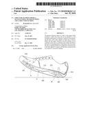
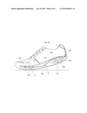
[0023]FIG. 5 is a perspective view illustrating the outer appearance of the shoe according to one embodiment of the invention;
[0024]FIG. 6 is a sectional view taken in the lengthwise direction of the shoe according to one embodiment of the invention;
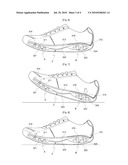
[0025]FIG. 7 is a sectional view illustrating the shoe according to one embodiment of the invention, in which the back portion of the sole of the shoe contacts the ground;
[0026]FIG. 8 is a sectional view illustrating the shoe according to one embodiment of the invention, in which the middle portion of the sole of the shoe contacts the ground; and
[0027]FIG. 9 is a sectional view illustrating the shoe according to one embodiment of the invention, in which the front portion of the sole of the shoe contacts the ground.
BEST MODE FOR CARRYING OUT THE INVENTION
[0028]A shoe according to one embodiment of the invention includes the shoe upper 100 having an open lower end which is near a sole assembly 300, and the sole assembly 300, which directly contacts the sole of a wearer's foot when a wearer wears the shoe and has a verity of functions which are performed when it contacts the sole of the wearer's foot.
[0029]The shoe upper 100 is made of leather or flexible synthetic material and has a form that can wrap around a wearer's foot from above. The shoe upper 100 has an opening 110 in the lower end thereof, which is near the sole assembly of the shoe. The basic structure of the shoe, which corresponds to the contour of the wearer's foot, is first set up, and then the lower end of the shoe upper 100 is attached to the sole assembly 300.
[0030]The opening of the shoe upper 100 fits the sole of the wearer's foot. Particularly, this embodiment relates to the case in which the opening is formed so as to expose the heel portion of the wearer's foot therethrough when the wearer's foot is put in the shoe upper 100.
[0031]With reference to FIG. 2, a wing 120 to be joined to the midsole 200 is connected to a front portion (toe-box portion) and a middle portion of the open lower end 110 of the shoe upper 100, and a constriction lace 130 is coupled to a back portion (heel-counter portion) of the open lower end 110 of the shoe upper 100. The constriction lace 130 is structured in a manner of constricting or loosening the heel-counter portion of the opening 110 of the shoe upper 100. The constriction lace 130 is coupled to the heel-counter portion of the open lower end 110 of the shoe upper 100 in a manner such that a string 140 is sewn to the lower end 110 of the shoe upper 100 so as to surround the constriction lace 130.
[0032]Accordingly, as shown in FIG. 3, the heel-contour portion of the opening of the shoe upper 100 is constricted inwardly when the constriction lace 130 is pulled. The lower end 110 of the shoe upper 100 can be easily and securely bonded to the sole assembly 300 while maintaining the state in which the heel-counter portion of the opening 120 is constricted. Accordingly, the heel of the wearer's foot can contact the sole assembly 300 over the entire area of a heel portion of the sole assembly 300.
[0033]The constriction lace 130 is not limited with respect to thickness or material, but a thinner and lighter one with sufficient durability is preferable.
[0034]On the other hand, the middle portion and the front portion (toebox portion) of the open lower end 110 of the shoe upper 100 are combined with the midsole 200 by bonding the wing 120 to the midsole 200. Thus, the basic shoe structure is set up. A flexible member 210 made of, for example, cushioning mesh, may be added to the back portion of the midsole 200. Accordingly, the shoe can be provided with the flexible member 210 at a heel portion of the sole thereof in a simple manner, for example, by attaching the midsole 200 to the shoe upper 100, and thus the flexible member 210 can be interposed between the sole of the wearer's foot and the sole assembly 300 of the shoe.
[0035]The midsole 200 has a ventilation window 220 in a position corresponding to a ventilation hole 314 formed in an upper midsole 310, so that air can be smoothly circulated in the shoe.
[0036]The sole assembly 300 has cushions arranged in the front portion and the back portion thereof, and the cushions become thicker going from the middle portion to the front end and the back end thereof, respectively. The overall inclination of the sole assembly is changed when the cushions are pressed by the weight of a wearer.
[0037]Accordingly, the wearer can feel comfortable when he or she walks thanks to the cushions provided at the front and back portions of the shoe. Moreover, the shoe positively affects the wearer's health because air circulation in the shoe is smoothly performed due to the presence of a pumping structure installed in the sole assembly 300.
[0038]As shown in FIGS. 4 to 6, the sole assembly 300 includes two midsoles and one outsole 330. The outsole 330 has a uniform thickness over the entire area thereof, and is abrasion resistant. The outsole 330 is attached to the bottom of a lower midsole. The two midsoles include an upper midsole 310 and a lower midsole 320. The upper midsole 310 is thickest in the middle portion thereof, and becomes thinner as it goes to the front end and the back end thereof, respectively. The upper midsole 310 is made of a relatively rigid material in comparison with the lower midsole 320. The lower midsole 320 is made of a cushiony material. The lower midsole 320 is thinnest in the middle portion thereof and becomes thicker toward the front end and the back end thereof, respectively. After the upper midsole 310 and the lower midsole 320 are combined with each other, the combination has a side having a V-shape with a gentle slope.
[0039]The lower midsole 320 has depressions 321 and 322 in the front portion and the back portion thereof, respectively, and a connection groove 323 is provided between the depressions 321 and 322. When the upper midsole 310 and the lower midsole 320 are combined and the gap between the upper midsole 310 and the lower midsole 320 is sealed, the depressions 321 and 322 and the connection groove 323 constitute a front pumping chamber A, a back pumping chamber B, and an air circulation path C, respectively.
[0040]It is preferable that the upper midsole 310 have depressions 311 and 312 and a connection groove 313 in the lower side thereof at positions corresponding to the depressions 321 and 322 and the connection groove 323, respectively provided to the lower midsole 320, in order to increase the sizes of the front pumping chamber A, the back bumping chamber B, and the air circulation path C. Thanks to this structure, the amount of air pumped and circulated is increased. Moreover, the midsole has a convex structure at the back portion (heel portion), which protrudes upward into a shoe, so that the heel of a wearer's foot comes into contact with the convex structure protruding through the opening 120 of the shoe upper 100 when the wearer wears the shoe. Thus, the pumping of air in the sole assembly of the shoe is facilitated.
[0041]The upper midsole 310 has the ventilation hole 314 in a position where the toes of the wearer are disposed, and the ventilation hole 314 is connected to the front pumping chamber A. Thus, the air in the sole assembly 300 is discharged into the space inside the shoe upper 100.
[0042]Inside the front pumping chamber A and the back pumping chamber B is further provided a shock absorbing member 324 which absorbs shocks attributable to pumping operation. The shock absorbing member 324 is provided to the lower midsole 320.
[0043]The shock absorbing member 324 can be any member which can absorb shocks. For example, the shock absorbing member 324 can be sponge, a cushion, or the like which can perform absorption due to its own material properties. Alternatively, the shock absorbing member 324 can be a spring, airbag, or the like which can perform absorption due to its structural properties. The shock absorbing member 324 can be other members which can perform absorption by any other methods.
[0044]The embodiment of the invention adopts a flexible synthetic resin as the shock absorbing member, which has a structure having a plurality of pillars. The shock absorbing member according to the embodiment absorbs shocks by distributing the shocks. It is preferable that the shock absorbing member be made of an antihygroscopic material so that the shock absorbing function is negligibly affected under high humidity condition.
[0045]Hereinafter, a method of manufacturing a shoe using the above-mentioned shoe upper 100 will be described.
[0046]The manufacturing method includes a step of setting up the basic structure of a shoe using the shoe upper 100, a step of manufacturing the sole assembly 300, and a step of completing the shoe by attaching the shoe upper 100 to the sole assembly 300.
[0047]In order to set up the basic structure of the shoe, the shoe last 150 is placed inside the shoe upper 100. The last 150 is a known mold cast having a foot shape, and is disposed inside the shoe upper to help form the basic structure of the shoe.
[0048]The wing 120 of the shoe upper 100 is bent inwards and the midsole 200 is attached to the wing 120 by gluing or sewing. Thus, the basic structure (toe box and middle portion) of the shoe has a shape corresponding to the shape of the shoe last 150. At this time, a flexible member 210 is coupled to the midsole 200, but is not coupled to the shoe upper 100.
[0049]Next, the constriction lace 130 constricts the heel-counter portion of the opening of the shoe upper 100, so that the heel-counter portion of the shoe upper comes to have a shape corresponding to a heel-counter portion of the shoe last, and then the constriction lace 130 is tied in the middle portion of the shoe. Next, a knot of the constriction lace 130 is pounded flat so that the knot does not come untied, and the shoe upper can be in tight contact with the sole assembly 300.
[0050]Next, in order to prepare the two midsoles of the sole assembly 300, the upper midsole 310 and the lower midsole 320 are combined with each other using glue, and then the outsole 330, made of a material having strong abrasion resistance and slip resistance, is attached to the bottom of the lower midsole 320. When combining the upper midsole 310 and the lower midsole 320, the depressions 311 and 321, the depressions 312 and 322, and the connection grooves 313 and 323 are precisely aligned with each other, and a gap formed between the opposing depressions 311 and 321, the opposing depressions 312 and 322, and the opposing connection grooves 313 and 323 is perfectly sealed. Accordingly, air in the sole assembly 300 cannot be discharged through any portion except through the ventilation hole 314.
[0051]Finally, the shoe upper 100 is glued to the outsole 330 of the sole assembly 300, by which the manufacturing process is finished.
[0052]The upper midsole 310 has a convex portion 310 protruding upward at the back portion thereof. Accordingly, the back portion of the upper midsole 310 contacts the shoe last 150 disposed inside the shoe upper 100. Accordingly, it is preferable that the shoe last 150 have a concave portion at a position corresponding to the convex portion of the upper midsole 310.
[0053]Hereinafter, the operation of the shoe will be described in the order of walking motions.
[0054]The shoe according to the embodiment of the invention has the same appearance as normal shoes. Accordingly, the overall structure of the sole of the shoe is flat and planar when it is not used.
[0055]When a wearer wears the shoe, the sole of the shoe has a down slope toward the heel portion of the shoe because the center of gravity of the wearer is on the heel side of the wearer. Accordingly, the wearer has a posture as if the wearer were going up an inclined surface. Thus, the wearer can obtain a mountain-climbing effect by doing every activity while wearing the shoe.
[0056]During walking, as shown in FIG. 7, the heel of the shoe touches the ground first. At this time, the heel of the wearer's foot directly presses the pumping chamber B provided in the sole assembly 300 at a portion surrounded by the constriction lace 130, so as to perform a pumping operation. At this time, air pumped out from the pumping chamber B flows to the pumping chamber A disposed at the front portion of the shoe, is discharged out from the space in the sole assembly 300, and is introduced into the inside of the shoe upper 100. Thus, the air is forcibly circulated.
[0057]After the heel of the shoe contacts the ground, the pumping operation is finished, and the overall structure of the sole is inclined downward toward the back of the shoe, as shown in FIG. 8, the center of gravity of the wearer's body is applied to the middle portion of the shoe in a subsequent step. At this time, since the height of the cushion is lowest at the middle portion, the rolling motion is conducted around the middle portion of the shoe as a pivot, and the pressure applied to the pumping chamber B is eliminated. Accordingly, the air in the shoe upper 100 is introduced into the pumping chamber B.
[0058]Next, as shown in FIG. 9, the center of gravity of the wearer's body is applied to the front portion of the shoe, so that the cushion at the front portion of the shoe is pressed more strongly, and rolling motions are continuously and smoothly performed. At this time, the pumping chamber A is pressed, and thus the air in the pumping chamber A is discharged outside the upper and lower midsoles.
[0059]Finally, when the bottom of the shoe is separated from the ground, the pressure applied to the pumping chamber A is eliminated, so that the air in the shoe upper is introduced again into the pumping chamber between upper and lower midsoles of the shoe.
INDUSTRIAL APPLICABILITY
[0060]The shoe upper, the shoe, and the manufacturing of the shoe according to the invention have the following advantages. Since the midsole has a large size opening which cannot be obtained through known shoe manufacturing techniques, it is possible to enhance the advantageous effects of the shoe, in which a variety of functions are imparted to the sole assembly and the functions are performed under a condition such that the sole of the wearer's foot can directly contact the sole assembly of the shoe.
[0061]Moreover, when the sole of the wearer's foot directly contacts the sole assembly, the shoe of the wearer's foot can effectively press the pumping chambers provided in the sole assembly. Accordingly, air in the sole assembly and the inside of the shoe can be forcibly circulated, and this contributes to an improvement of the wearer's health. Further, thanks to the specific structure of the sole assembly provided in the shoe of the invention, the wearer can obtain a mountain climbing effect and feel comfortable when the wearer walks while wearing the shoe.
Claims:
1. A shoe upper which constitutes a shoe by being attached to a sole
assembly, comprising:a constriction lace provided at a first part of an
opening of the shoe upper which directly contacts the sole assembly; anda
coupling member for coupling the constriction lace to the shoe upper in a
manner such that the constriction lace constricts or loosens the first
part of the opening of the shoe upper.
2. The shoe upper according to claim 1, wherein the coupling member is a string sewn along a boundary of the first part of the opening of the shoe upper.
3. The shoe upper according to claim 1, further comprising a midsole attached to a second part of the opening at a position at which the constriction lace is not provided.
4. The shoe upper according to claim 3, wherein a flexible member is provided in the first part of the opening of the shoe upper, which is surrounded by the constriction lace.
5. A method of manufacturing a shoe which is manufactured by attaching a shoe upper having a constriction lace surrounding a first part of an opening of the shoe upper, which directly contacts a sole assembly, and a coupling member for coupling the shoe lace to the first part of the shoe upper so that the constriction lace constricts or loosens the first part of the opening, to the sole assembly, comprising:setting up a basic shoe structure by placing a shoe last into the shoe upper and then constricting the first part of the opening by pulling the constriction lace so that the opening comes to have a form corresponding to a form of the shoe last; processing the constriction lace so that a knot of the constriction lace does not come untied; andcompleting the shoe in which the sole assembly is visible through the opening of the shoe upper by attaching the shoe upper to the sole assembly.
6. The method according to claim 5, wherein the coupling member is a string sewn to a boundary of the first part of the opening of the shoe upper in a manner of surrounding the constriction lace.
7. The method according to claim 5, wherein the processing is performed by constricting the opening by pulling the constriction lace, forming a knot, and pounding the knot to be flat.
8. The method according to claim 7, wherein the opening is constricted after a midsole is attached to a second part of the shoe upper, the second part not being surrounded by the constriction lace.
9. A shoe having a shoe upper with an opening which is near a sole assembly and the sole assembly being visible inside the shoe, thanks to a structure in which the shoe upper is attached to the sole assembly after a basic shoe structure is set up by constricting part of the opening of the shoe upper using a constriction lace, wherein the sole assembly has a cushion which is thickest in a middle portion thereof and becomes thicker as it goes to a front end and a back end thereof, respectively, and wherein the cushion is pressed at a front portion and a back portion by weight of a wearer, so that the overall slope of the sole assembly is changed when the wearer wears the shoe.
10. The shoe according to claim 9, wherein the sole assembly includes:an upper midsole which is thickest in a middle portion thereof and becomes thinner as it goes to a front end and a back end, respectively, thereof;a lower midsole which is thinnest in a middle portion thereof and becomes thicker as it goes to a front end and a back end, respectively, thereof; andan outsole having abrasion resistance and attached to a lower surface of the lower midsole.
11. The shoe according to claim in wherein pumping chambers are provided in a front portion and a back portion of the shoe by combining the upper midsole and the lower midsole, an air circulation passage is provided between the pumping chambers, and at least one air discharge hole is provided to the upper midsole in order to discharge air from the pumping chambers into the shoe upper.
12. The shoe according to claim 11, wherein the air circulation path is constituted by a connection groove formed between a front pumping chamber and a back pumping chamber provided to the upper midsole and a connection groove formed between a front pumping chamber and a back pumping chamber provided to the lower midsole.
13. The shoe according to claim 11, wherein a shock absorbing member is provided to the pumping chamber in the lower midsole in order to absorb shocks attributable to pumping operation.
14. The shoe upper according to claim 2, further comprising a midsole attached to a second part of the opening at a position at which the constriction lace is not provided.
15. The method according to claim 6, wherein the processing is performed by constricting the opening by pulling the constriction lace, forming a knot, and pounding the knot to be flat.
Description:
TECHNICAL FIELD
[0001]The present invention relates to a shoe, and more particularly to a shoe upper which can maintain a stable shoe structure and can be attached to a sole assembly lacking part of a midsole, a method of manufacturing a shoe, and a shoe having a function of improving the wearer's health.
BACKGROUND ART
[0002]Shoes absorb shocks and protect wearer's feet when wearers move. A shoe is generally manufactured by first setting up the basic shoe structure by bonding the midsole to the entire lower end of the shoe upper and then by bonding the midsole to the outsole.
[0003]With the recent increased interest in health, techniques for a variety of shoes which can positively affect wearer's health have been suggested. Among the techniques, a technique in which particular functions are provided to the outsole of a shoe and the functions are performed when a wearer walks while wearing the shoe is popular. In this technique, further improvement is demanded in order to make the functions provided to the outsole be more effectively performed by making the sole of a wearer's foot directly contact the outsole of the shoe instead of contacting the midsole.
[0004]Korean Patent 627728, the application for which was filed in 2006 and which has now been granted, discloses a known technique in which the outsole is divided into an upper layer and a lower layer. Further, part of the outsole, made of a cushiony material, protrudes upward into the shoe through the opening formed in the midsole and the upper layer of the outsole, so that the cushion of the outsole comes into direct contact with the heel of a wearer. Thanks to this structure, the wearer can feel cushioned and comfortable when the wearer walks while wearing the shoe.
[0005]Until now, as for all shoes, the basic shoe structure is set up in a way that the shoe upper is combined with the outsole in the presence of the midsole therebetween. Accordingly, direct contact between the sole of a wearer's foot and the outsole of the shoe can only be accomplished using a midsole having an aperture through which part of the outsole is visible.
[0006]The technique of using the midsole with an aperture is disadvantageous in that the aperture size is not sufficiently large because the area of the midsole in which the aperture can be formed is limited. That is, the aperture can be provided only in a portion of the midsole other than a bonding region in which the shoe upper and the midsole are bonded to each other.
[0007]Accordingly, the sole of a wearer's foot cannot sufficiently contact the outsole of a shoe, so that the functions imparted to the outsole cannot be sufficiently performed when the wearer walks.
DISCLOSURE OF INVENTION
Technical Problem
[0008]The object of the invention is to provide a shoe upper capable of forming a basic shoe structure, which can be attached to a sole assembly lacking part of a midsole, and a method of manufacturing a shoe using the shoe upper.
[0009]Another object of the invention are to provide a shoe having a function of positively affecting a wearer's health thanks to the structure in which the sole of the wearer's foot can sufficiently contact the sole assembly of the shoe due to the shoe upper and the manufacturing method.
Technical Solution
[0010]In order to solve the various problems encountered in the known art, and in order to achieve the above described advantageous effects and features, in accordance with one aspect of the invention, there is provided a shoe upper which constitutes a shoe by being attached to a sole assembly, including a constriction lace provided at a first part of an opening of the shoe upper which directly contacts the sole assembly, and a coupling member for coupling the constriction lace to the shoe upper in a manner such that the constriction lace constricts or loosens the first part of the opening of the shoe upper.
[0011]In the shoe upper, it is preferable that the coupling member be a string sewn along the first part of the opening and that the shoe upper further comprise a midsole attached to a second part of the opening at a position in which the constriction lace is not provided.
[0012]In the shoe upper, it is preferable that the midsole have a flexible member at a position corresponding to the first part of the opening, which is surrounded by the constriction lace.
[0013]According to another aspect of the invention, there is provided a method of manufacturing a shoe including a step of setting up a basic shoe structure corresponding to a form of a shoe last using a shoe upper by placing the shoe last into the shoe upper and then constricting an opening of a lower open end of the shoe upper by pulling the constriction lace, processing the constriction lace so that a knot of the constriction lace does not come to be untied, and completing the shoe, the sole assembly of which protrudes upward through the opening in the shoe upper, by attaching the shoe upper to the sole assembly.
[0014]In the method, it is preferable that the coupling member be a string sewn to a boundary of the opening of the shoe upper in a manner of surrounding the constriction lace and that the processing be performed by constricting the opening by pulling the constriction lace, forming a knot, and making the knot flat.
[0015]In the method, it is preferable that the opening be constricted after a midsole is attached to part of the shoe upper, the part not being surrounded by the constriction lace.
[0016]According to a further aspect of the invention, there is provided a shoe constituted by attaching a shoe upper to a sole assembly, in which the sole assembly is visible inside the shoe, wherein the sole assembly has a cushion which is thickest in the middle portion thereof and becomes thicker going to the front end and the back end thereof, respectively, and wherein the cushion is pressed at the front portion and the back portion by the weight of a wearer, so that the overall slope of the sole assembly is changed when the wearer wears the shoe.
[0017]In the shoe, it is preferable that the sole assembly include an upper midsole which is thickest in the middle portion thereof and becomes thinner going to the front end and the back end thereof, a lower midsole which is thinnest in the middle portion thereof and becomes thicker going to the front end and the back end thereof, and an outsole having abrasion resistance and being attached to the lower surface of the lower midsole, in which pumping chambers are provided in the front portion and the back portion of the shoe by combining the upper midsole and the lower midsole, an air circulation passage is provided between the pumping chambers, and at least one air discharge hole is provided to the upper midsole in order to discharge out air from the pumping chambers into the shoe upper.
[0018]In the shoe, it is preferable that the air circulation path be constituted by a connection groove between a front pumping chamber and a back pumping chamber provided to the upper midsole and a connection groove between a front pumping chamber and a back pumping chamber provided to the lower midsole.
BRIEF DESCRIPTION OF THE DRAWINGS
[0019]FIG. 1 is an exploded perspective view illustrating a known show structure of a shoe;
[0020]FIG. 2 is an exploded perspective view illustrating the shoe upper and the midsole of a shoe according to one embodiment of the invention;
[0021]FIG. 3 is a perspective view illustrating the shoe upper and the midsole combined with each other according to one embodiment of the invention;
[0022]FIG. 4 is an exploded perspective view illustrating a sole assembly of the shoe according to one embodiment of the invention;
[0023]FIG. 5 is a perspective view illustrating the outer appearance of the shoe according to one embodiment of the invention;
[0024]FIG. 6 is a sectional view taken in the lengthwise direction of the shoe according to one embodiment of the invention;
[0025]FIG. 7 is a sectional view illustrating the shoe according to one embodiment of the invention, in which the back portion of the sole of the shoe contacts the ground;
[0026]FIG. 8 is a sectional view illustrating the shoe according to one embodiment of the invention, in which the middle portion of the sole of the shoe contacts the ground; and
[0027]FIG. 9 is a sectional view illustrating the shoe according to one embodiment of the invention, in which the front portion of the sole of the shoe contacts the ground.
BEST MODE FOR CARRYING OUT THE INVENTION
[0028]A shoe according to one embodiment of the invention includes the shoe upper 100 having an open lower end which is near a sole assembly 300, and the sole assembly 300, which directly contacts the sole of a wearer's foot when a wearer wears the shoe and has a verity of functions which are performed when it contacts the sole of the wearer's foot.
[0029]The shoe upper 100 is made of leather or flexible synthetic material and has a form that can wrap around a wearer's foot from above. The shoe upper 100 has an opening 110 in the lower end thereof, which is near the sole assembly of the shoe. The basic structure of the shoe, which corresponds to the contour of the wearer's foot, is first set up, and then the lower end of the shoe upper 100 is attached to the sole assembly 300.
[0030]The opening of the shoe upper 100 fits the sole of the wearer's foot. Particularly, this embodiment relates to the case in which the opening is formed so as to expose the heel portion of the wearer's foot therethrough when the wearer's foot is put in the shoe upper 100.
[0031]With reference to FIG. 2, a wing 120 to be joined to the midsole 200 is connected to a front portion (toe-box portion) and a middle portion of the open lower end 110 of the shoe upper 100, and a constriction lace 130 is coupled to a back portion (heel-counter portion) of the open lower end 110 of the shoe upper 100. The constriction lace 130 is structured in a manner of constricting or loosening the heel-counter portion of the opening 110 of the shoe upper 100. The constriction lace 130 is coupled to the heel-counter portion of the open lower end 110 of the shoe upper 100 in a manner such that a string 140 is sewn to the lower end 110 of the shoe upper 100 so as to surround the constriction lace 130.
[0032]Accordingly, as shown in FIG. 3, the heel-contour portion of the opening of the shoe upper 100 is constricted inwardly when the constriction lace 130 is pulled. The lower end 110 of the shoe upper 100 can be easily and securely bonded to the sole assembly 300 while maintaining the state in which the heel-counter portion of the opening 120 is constricted. Accordingly, the heel of the wearer's foot can contact the sole assembly 300 over the entire area of a heel portion of the sole assembly 300.
[0033]The constriction lace 130 is not limited with respect to thickness or material, but a thinner and lighter one with sufficient durability is preferable.
[0034]On the other hand, the middle portion and the front portion (toebox portion) of the open lower end 110 of the shoe upper 100 are combined with the midsole 200 by bonding the wing 120 to the midsole 200. Thus, the basic shoe structure is set up. A flexible member 210 made of, for example, cushioning mesh, may be added to the back portion of the midsole 200. Accordingly, the shoe can be provided with the flexible member 210 at a heel portion of the sole thereof in a simple manner, for example, by attaching the midsole 200 to the shoe upper 100, and thus the flexible member 210 can be interposed between the sole of the wearer's foot and the sole assembly 300 of the shoe.
[0035]The midsole 200 has a ventilation window 220 in a position corresponding to a ventilation hole 314 formed in an upper midsole 310, so that air can be smoothly circulated in the shoe.
[0036]The sole assembly 300 has cushions arranged in the front portion and the back portion thereof, and the cushions become thicker going from the middle portion to the front end and the back end thereof, respectively. The overall inclination of the sole assembly is changed when the cushions are pressed by the weight of a wearer.
[0037]Accordingly, the wearer can feel comfortable when he or she walks thanks to the cushions provided at the front and back portions of the shoe. Moreover, the shoe positively affects the wearer's health because air circulation in the shoe is smoothly performed due to the presence of a pumping structure installed in the sole assembly 300.
[0038]As shown in FIGS. 4 to 6, the sole assembly 300 includes two midsoles and one outsole 330. The outsole 330 has a uniform thickness over the entire area thereof, and is abrasion resistant. The outsole 330 is attached to the bottom of a lower midsole. The two midsoles include an upper midsole 310 and a lower midsole 320. The upper midsole 310 is thickest in the middle portion thereof, and becomes thinner as it goes to the front end and the back end thereof, respectively. The upper midsole 310 is made of a relatively rigid material in comparison with the lower midsole 320. The lower midsole 320 is made of a cushiony material. The lower midsole 320 is thinnest in the middle portion thereof and becomes thicker toward the front end and the back end thereof, respectively. After the upper midsole 310 and the lower midsole 320 are combined with each other, the combination has a side having a V-shape with a gentle slope.
[0039]The lower midsole 320 has depressions 321 and 322 in the front portion and the back portion thereof, respectively, and a connection groove 323 is provided between the depressions 321 and 322. When the upper midsole 310 and the lower midsole 320 are combined and the gap between the upper midsole 310 and the lower midsole 320 is sealed, the depressions 321 and 322 and the connection groove 323 constitute a front pumping chamber A, a back pumping chamber B, and an air circulation path C, respectively.
[0040]It is preferable that the upper midsole 310 have depressions 311 and 312 and a connection groove 313 in the lower side thereof at positions corresponding to the depressions 321 and 322 and the connection groove 323, respectively provided to the lower midsole 320, in order to increase the sizes of the front pumping chamber A, the back bumping chamber B, and the air circulation path C. Thanks to this structure, the amount of air pumped and circulated is increased. Moreover, the midsole has a convex structure at the back portion (heel portion), which protrudes upward into a shoe, so that the heel of a wearer's foot comes into contact with the convex structure protruding through the opening 120 of the shoe upper 100 when the wearer wears the shoe. Thus, the pumping of air in the sole assembly of the shoe is facilitated.
[0041]The upper midsole 310 has the ventilation hole 314 in a position where the toes of the wearer are disposed, and the ventilation hole 314 is connected to the front pumping chamber A. Thus, the air in the sole assembly 300 is discharged into the space inside the shoe upper 100.
[0042]Inside the front pumping chamber A and the back pumping chamber B is further provided a shock absorbing member 324 which absorbs shocks attributable to pumping operation. The shock absorbing member 324 is provided to the lower midsole 320.
[0043]The shock absorbing member 324 can be any member which can absorb shocks. For example, the shock absorbing member 324 can be sponge, a cushion, or the like which can perform absorption due to its own material properties. Alternatively, the shock absorbing member 324 can be a spring, airbag, or the like which can perform absorption due to its structural properties. The shock absorbing member 324 can be other members which can perform absorption by any other methods.
[0044]The embodiment of the invention adopts a flexible synthetic resin as the shock absorbing member, which has a structure having a plurality of pillars. The shock absorbing member according to the embodiment absorbs shocks by distributing the shocks. It is preferable that the shock absorbing member be made of an antihygroscopic material so that the shock absorbing function is negligibly affected under high humidity condition.
[0045]Hereinafter, a method of manufacturing a shoe using the above-mentioned shoe upper 100 will be described.
[0046]The manufacturing method includes a step of setting up the basic structure of a shoe using the shoe upper 100, a step of manufacturing the sole assembly 300, and a step of completing the shoe by attaching the shoe upper 100 to the sole assembly 300.
[0047]In order to set up the basic structure of the shoe, the shoe last 150 is placed inside the shoe upper 100. The last 150 is a known mold cast having a foot shape, and is disposed inside the shoe upper to help form the basic structure of the shoe.
[0048]The wing 120 of the shoe upper 100 is bent inwards and the midsole 200 is attached to the wing 120 by gluing or sewing. Thus, the basic structure (toe box and middle portion) of the shoe has a shape corresponding to the shape of the shoe last 150. At this time, a flexible member 210 is coupled to the midsole 200, but is not coupled to the shoe upper 100.
[0049]Next, the constriction lace 130 constricts the heel-counter portion of the opening of the shoe upper 100, so that the heel-counter portion of the shoe upper comes to have a shape corresponding to a heel-counter portion of the shoe last, and then the constriction lace 130 is tied in the middle portion of the shoe. Next, a knot of the constriction lace 130 is pounded flat so that the knot does not come untied, and the shoe upper can be in tight contact with the sole assembly 300.
[0050]Next, in order to prepare the two midsoles of the sole assembly 300, the upper midsole 310 and the lower midsole 320 are combined with each other using glue, and then the outsole 330, made of a material having strong abrasion resistance and slip resistance, is attached to the bottom of the lower midsole 320. When combining the upper midsole 310 and the lower midsole 320, the depressions 311 and 321, the depressions 312 and 322, and the connection grooves 313 and 323 are precisely aligned with each other, and a gap formed between the opposing depressions 311 and 321, the opposing depressions 312 and 322, and the opposing connection grooves 313 and 323 is perfectly sealed. Accordingly, air in the sole assembly 300 cannot be discharged through any portion except through the ventilation hole 314.
[0051]Finally, the shoe upper 100 is glued to the outsole 330 of the sole assembly 300, by which the manufacturing process is finished.
[0052]The upper midsole 310 has a convex portion 310 protruding upward at the back portion thereof. Accordingly, the back portion of the upper midsole 310 contacts the shoe last 150 disposed inside the shoe upper 100. Accordingly, it is preferable that the shoe last 150 have a concave portion at a position corresponding to the convex portion of the upper midsole 310.
[0053]Hereinafter, the operation of the shoe will be described in the order of walking motions.
[0054]The shoe according to the embodiment of the invention has the same appearance as normal shoes. Accordingly, the overall structure of the sole of the shoe is flat and planar when it is not used.
[0055]When a wearer wears the shoe, the sole of the shoe has a down slope toward the heel portion of the shoe because the center of gravity of the wearer is on the heel side of the wearer. Accordingly, the wearer has a posture as if the wearer were going up an inclined surface. Thus, the wearer can obtain a mountain-climbing effect by doing every activity while wearing the shoe.
[0056]During walking, as shown in FIG. 7, the heel of the shoe touches the ground first. At this time, the heel of the wearer's foot directly presses the pumping chamber B provided in the sole assembly 300 at a portion surrounded by the constriction lace 130, so as to perform a pumping operation. At this time, air pumped out from the pumping chamber B flows to the pumping chamber A disposed at the front portion of the shoe, is discharged out from the space in the sole assembly 300, and is introduced into the inside of the shoe upper 100. Thus, the air is forcibly circulated.
[0057]After the heel of the shoe contacts the ground, the pumping operation is finished, and the overall structure of the sole is inclined downward toward the back of the shoe, as shown in FIG. 8, the center of gravity of the wearer's body is applied to the middle portion of the shoe in a subsequent step. At this time, since the height of the cushion is lowest at the middle portion, the rolling motion is conducted around the middle portion of the shoe as a pivot, and the pressure applied to the pumping chamber B is eliminated. Accordingly, the air in the shoe upper 100 is introduced into the pumping chamber B.
[0058]Next, as shown in FIG. 9, the center of gravity of the wearer's body is applied to the front portion of the shoe, so that the cushion at the front portion of the shoe is pressed more strongly, and rolling motions are continuously and smoothly performed. At this time, the pumping chamber A is pressed, and thus the air in the pumping chamber A is discharged outside the upper and lower midsoles.
[0059]Finally, when the bottom of the shoe is separated from the ground, the pressure applied to the pumping chamber A is eliminated, so that the air in the shoe upper is introduced again into the pumping chamber between upper and lower midsoles of the shoe.
INDUSTRIAL APPLICABILITY
[0060]The shoe upper, the shoe, and the manufacturing of the shoe according to the invention have the following advantages. Since the midsole has a large size opening which cannot be obtained through known shoe manufacturing techniques, it is possible to enhance the advantageous effects of the shoe, in which a variety of functions are imparted to the sole assembly and the functions are performed under a condition such that the sole of the wearer's foot can directly contact the sole assembly of the shoe.
[0061]Moreover, when the sole of the wearer's foot directly contacts the sole assembly, the shoe of the wearer's foot can effectively press the pumping chambers provided in the sole assembly. Accordingly, air in the sole assembly and the inside of the shoe can be forcibly circulated, and this contributes to an improvement of the wearer's health. Further, thanks to the specific structure of the sole assembly provided in the shoe of the invention, the wearer can obtain a mountain climbing effect and feel comfortable when the wearer walks while wearing the shoe.
User Contributions:
Comment about this patent or add new information about this topic:
Images included with this patent application:
 |  |
 |  |
 |
| Similar patent applications: | |
| Date | Title |
|---|---|
| 2013-06-27 | Article of footwear having an elevated plate sole structure |
| 2013-06-27 | Article of footwear having an elevated plate sole structure |
| 2013-06-27 | Article of footwear having an elevated plate sole structure |
| 2010-03-11 | Structure of bottom of shoes |
| 2011-09-22 | Shoe molding and fixing structure |
| New patent applications in this class: | |
| Date | Title |
|---|---|
| 2018-01-25 | Mechanical ventilation system and device for footwear |
| 2016-06-30 | Footbed having functions of acupuncture point massage and reducing pressure |
| 2016-05-05 | Article of footwear and method for forming the article |
| 2016-03-17 | Item of footwear with ventilation in the bottom region of the shaft, and air-permeable spacer structure which can be used for this purpose |
| 2016-02-04 | Shoe having active air ventilation |
| New patent applications from these inventors: | |
| Date | Title |
|---|---|
| 2014-07-03 | Structure of shoe sole having superior ventilation function and double- landing function |
| 2009-05-07 | Sole structure of footwear |
| Top Inventors for class "Boots, shoes, and leggings" | |
| Rank | Inventor's name |
|---|---|
| 1 | Frederick J. Dojan |
| 2 | Michael A. Aveni |
| 3 | Perry W. Auger |
| 4 | Sergio Cavaliere |
| 5 | Lee D. Peyton |