Patent application title: MORE ELECTRIC ENGINE WITH REGULATED PERMANENT MAGNET MACHINES
Inventors:
Gregory I. Rozman (Rockford, IL, US)
Kevin P. Roy (West Springfield, MA, US)
Kevin P. Roy (West Springfield, MA, US)
IPC8 Class: AB60L100FI
USPC Class:
307 91
Class name: Electrical transmission or interconnection systems vehicle mounted systems
Publication date: 2010-06-10
Patent application number: 20100141028
d power supply system comprises a prime mover for
driving a shaft to rotate. A pair of permanent magnets is associated with
the rotating shaft. A first stator winding is associated with a first of
said permanent magnets, with a customer DC bus for providing a first
relatively low voltage to the customer DC bus. A second of said permanent
magnets is associated with a second stator winding, and an engine
accessory DC bus. The engine accessory DC bus provides power to a motor
controller and associated accessory motors associated with the prime
mover. The engine accessory DC bus is provided with a second relatively
high voltage from the second stator winding.Claims:
1. A generator and associated power supply system comprising:a prime mover
for driving a shaft to rotate;at least a pair of permanent magnets
associated with said shaft;a first stator winding associated with a first
of said permanent magnets, said first stator winding associated with a
customer DC bus, and providing a first relatively low voltage to said
customer DC bus; anda second of said permanent magnets being associated
with a second set of stator winding, and communicating with an engine
accessory DC bus, said engine accessory DC bus providing power to a motor
controller and an associated motor for an accessory associated with said
prime mover, said engine accessory DC bus being provided with a second
relatively high voltage from said second stator windings.
2. The system as set forth in claim 1, wherein said prime mover is a gas turbine engine.
3. The system as set forth in claim 1, wherein said customer DC bus is associated with components on an airplane.
4. The system as set forth in claim 1, wherein both of said windings ultimately communicate with a bi-directional DC/DC converter.
5. The system as set forth in claim 4, wherein said bi-directional DC/DC converter allows the power from said first stator winding to be also directed to said engine accessory DC bus, and allows the power from said second stator winding to be selectively sent to said customer DC bus, as necessary.
6. The system as set forth in claim 1, wherein said engine accessory bus communicates with a plurality of motor controllers and a plurality of motors.
7. The system as set forth in claim 6, wherein said plurality of motors include at least a fuel and oil pump motor.
8. The system as set forth in claim 1, wherein said first voltage is on the order of 28 volts and said second voltage is over 100 volts.
9. The system as set forth in claim 8, wherein said second voltage is on the order of 270 volts.
10. A generator and associated power supply system comprising:a prime mover for driving a shaft to rotate;at least a pair of permanent magnets associated with said shaft;a first stator winding associated with a first of said permanent magnets, said first stator winding associated with a customer DC bus, and providing a first relatively low voltage to said customer DC bus;a second of said permanent magnets being associated with a second set of stator winding, and communicating with an engine accessory DC bus, said engine accessory DC bus providing power to a plurality of motor controllers and associated motors for accessories associated with said prime mover, and including at least a fuel pump motor and an oil pump motor, said engine accessory DC bus being provided with a second relatively high voltage from said second stator windings;said prime mover being a gas turbine engine, said customer DC bus being associated with components on an airplane;both of said windings ultimately communicate with a bi-directional DC/DC converter, that allows the power from said first stator winding to be also directed to said engine accessory DC bus, and allows the power from said second stator winding to be selectively sent to said customer DC bus, as necessary; andsaid first voltage being on the order of 28 volts and said second voltage being on the order of 270 volts.Description:
BACKGROUND OF THE INVENTION
[0001]This application relates to an electrical generation system wherein separate permanent magnet generators and associated buses are provided for a load, and for accessories associated with the generator.
[0002]Generators for generating electricity are known. One common generator is provided by a gas turbine engine, such as on an aircraft.
[0003]Recently, an electrical system associated with a gas turbine engine has been developed to provide electricity to a DC bus for providing power to various components associated with an aircraft carrying the gas turbine engine. A separate bus is provided to provide power and control signals to pumps and other motors associated with the engine itself.
[0004]One challenge with such a system is that the engine accessories tend to need increased voltage levels compared to the other components on the aircraft.
[0005]Providing such distinct voltage levels has proved challenging, and has raised cost and weight, as well as harming efficiency.
SUMMARY OF THE INVENTION
[0006]A generator and associated power supply system comprises a prime mover for driving a shaft to rotate. At least a pair of permanent magnets is associated with the rotating shaft. A first stator winding is associated with a first of said permanent magnets, with a customer DC bus for providing a first relatively low voltage to the customer DC bus. A second of said permanent magnets is associated with a second stator winding, and an engine accessory DC bus. The engine accessory DC bus provides power to a motor controller and associated accessory motors associated with the prime mover. The engine accessory DC bus is provided with a second relatively high voltage from the second stator winding.
[0007]These and other features of the present invention can be best understood from the following specification and drawings, the following of which is a brief description.
BRIEF DESCRIPTION OF THE DRAWINGS
[0008]The sole FIGURE is a schematic of an inventive generator and associated system.
DETAILED DESCRIPTION OF THE PREFERRED EMBODIMENT
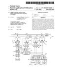
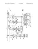
[0009]A generator and electrical supply system 20 for use, such as on an airplane, includes a prime mover 22, which may be a gas turbine engine. Prime mover 22 drives a shaft 24. Permanent magnets 26 and 28 rotate with the shaft 24. A three-phase stator winding 30 is positioned adjacent the magnet 26, and supplies current through a rectifier 32, a filter 34, a circuit breaker 36, and to a customer DC bus 38. The customer DC bus 38 may supply electrical power such as to various systems and components on an airplane.
[0010]A control winding 40 is provided to control the current and voltage supplied to the bus 38. A current sensor 42 provides sensed current to a voltage regulator 46, and a voltage sensor 48 does the same. An H-bridge 42 is associated with this control circuitry. A diode OR gate 50 is associated into the circuitry to enable control power to the voltage regulator from either power quality filter 34, or from bi-directional dc/dc converter 52.
[0011]A bidirectional DC/DC converter 52 has a function to be described below.
[0012]The control side of this circuit operates as is known to control the power supplied to the customer DC bus 38. Generally, the system is provided to provide a relatively low voltage to the customer DC bus 38. In one example, this may be a 28 volt power supply.
[0013]A somewhat similar system is disclosed in U.S. patent application Ser. No. 11/839,763, filed Aug. 16, 2007, which is owned by the assignee of the present application, and titled "Engine Having Power Bus Fault Short Circuit Control With A Disconnection Switch."
[0014]In parallel with the power supply to the customer DC bus 38, the magnet 28 rotates adjacent stator windings 54. A control winding 56 is associated with components similar to the control winding 40.
[0015]This power is supplied separately to an engine accessory DC bus 58. The power supplied from bus 58 passes to motor controller 60 which separately controls individual components associated with the engine such as an actuator motor 62, a fuel pump 64, or an oil pump 66.
[0016]The permanent magnet 28 and its associated windings 54 and 56 are configured such that they will provide a relatively high voltage, for example, on the order of 270 volts to the controllers and pumps 60, 62, 64, and 66.
[0017]With the present invention, a relatively simple system is able to provide distinct voltages to the two buses 38 and 58.
[0018]The DC/DC power converter 52 utilizes a current mode control to enable optimized battery charging during the generation mode, but also enables power to the accessory bus 58 from the aircraft's battery during engine start. Also, the bi-directional feature allows either power supply to direct power to the other, should there be some failure.
[0019]Although an embodiment of this invention has been disclosed, a worker of ordinary skill in this art would recognize that certain modifications would come within the scope of this invention. For that reason, the following claims should be studied to determine the true scope and content of this invention.
Claims:
1. A generator and associated power supply system comprising:a prime mover
for driving a shaft to rotate;at least a pair of permanent magnets
associated with said shaft;a first stator winding associated with a first
of said permanent magnets, said first stator winding associated with a
customer DC bus, and providing a first relatively low voltage to said
customer DC bus; anda second of said permanent magnets being associated
with a second set of stator winding, and communicating with an engine
accessory DC bus, said engine accessory DC bus providing power to a motor
controller and an associated motor for an accessory associated with said
prime mover, said engine accessory DC bus being provided with a second
relatively high voltage from said second stator windings.
2. The system as set forth in claim 1, wherein said prime mover is a gas turbine engine.
3. The system as set forth in claim 1, wherein said customer DC bus is associated with components on an airplane.
4. The system as set forth in claim 1, wherein both of said windings ultimately communicate with a bi-directional DC/DC converter.
5. The system as set forth in claim 4, wherein said bi-directional DC/DC converter allows the power from said first stator winding to be also directed to said engine accessory DC bus, and allows the power from said second stator winding to be selectively sent to said customer DC bus, as necessary.
6. The system as set forth in claim 1, wherein said engine accessory bus communicates with a plurality of motor controllers and a plurality of motors.
7. The system as set forth in claim 6, wherein said plurality of motors include at least a fuel and oil pump motor.
8. The system as set forth in claim 1, wherein said first voltage is on the order of 28 volts and said second voltage is over 100 volts.
9. The system as set forth in claim 8, wherein said second voltage is on the order of 270 volts.
10. A generator and associated power supply system comprising:a prime mover for driving a shaft to rotate;at least a pair of permanent magnets associated with said shaft;a first stator winding associated with a first of said permanent magnets, said first stator winding associated with a customer DC bus, and providing a first relatively low voltage to said customer DC bus;a second of said permanent magnets being associated with a second set of stator winding, and communicating with an engine accessory DC bus, said engine accessory DC bus providing power to a plurality of motor controllers and associated motors for accessories associated with said prime mover, and including at least a fuel pump motor and an oil pump motor, said engine accessory DC bus being provided with a second relatively high voltage from said second stator windings;said prime mover being a gas turbine engine, said customer DC bus being associated with components on an airplane;both of said windings ultimately communicate with a bi-directional DC/DC converter, that allows the power from said first stator winding to be also directed to said engine accessory DC bus, and allows the power from said second stator winding to be selectively sent to said customer DC bus, as necessary; andsaid first voltage being on the order of 28 volts and said second voltage being on the order of 270 volts.
Description:
BACKGROUND OF THE INVENTION
[0001]This application relates to an electrical generation system wherein separate permanent magnet generators and associated buses are provided for a load, and for accessories associated with the generator.
[0002]Generators for generating electricity are known. One common generator is provided by a gas turbine engine, such as on an aircraft.
[0003]Recently, an electrical system associated with a gas turbine engine has been developed to provide electricity to a DC bus for providing power to various components associated with an aircraft carrying the gas turbine engine. A separate bus is provided to provide power and control signals to pumps and other motors associated with the engine itself.
[0004]One challenge with such a system is that the engine accessories tend to need increased voltage levels compared to the other components on the aircraft.
[0005]Providing such distinct voltage levels has proved challenging, and has raised cost and weight, as well as harming efficiency.
SUMMARY OF THE INVENTION
[0006]A generator and associated power supply system comprises a prime mover for driving a shaft to rotate. At least a pair of permanent magnets is associated with the rotating shaft. A first stator winding is associated with a first of said permanent magnets, with a customer DC bus for providing a first relatively low voltage to the customer DC bus. A second of said permanent magnets is associated with a second stator winding, and an engine accessory DC bus. The engine accessory DC bus provides power to a motor controller and associated accessory motors associated with the prime mover. The engine accessory DC bus is provided with a second relatively high voltage from the second stator winding.
[0007]These and other features of the present invention can be best understood from the following specification and drawings, the following of which is a brief description.
BRIEF DESCRIPTION OF THE DRAWINGS
[0008]The sole FIGURE is a schematic of an inventive generator and associated system.
DETAILED DESCRIPTION OF THE PREFERRED EMBODIMENT
[0009]A generator and electrical supply system 20 for use, such as on an airplane, includes a prime mover 22, which may be a gas turbine engine. Prime mover 22 drives a shaft 24. Permanent magnets 26 and 28 rotate with the shaft 24. A three-phase stator winding 30 is positioned adjacent the magnet 26, and supplies current through a rectifier 32, a filter 34, a circuit breaker 36, and to a customer DC bus 38. The customer DC bus 38 may supply electrical power such as to various systems and components on an airplane.
[0010]A control winding 40 is provided to control the current and voltage supplied to the bus 38. A current sensor 42 provides sensed current to a voltage regulator 46, and a voltage sensor 48 does the same. An H-bridge 42 is associated with this control circuitry. A diode OR gate 50 is associated into the circuitry to enable control power to the voltage regulator from either power quality filter 34, or from bi-directional dc/dc converter 52.
[0011]A bidirectional DC/DC converter 52 has a function to be described below.
[0012]The control side of this circuit operates as is known to control the power supplied to the customer DC bus 38. Generally, the system is provided to provide a relatively low voltage to the customer DC bus 38. In one example, this may be a 28 volt power supply.
[0013]A somewhat similar system is disclosed in U.S. patent application Ser. No. 11/839,763, filed Aug. 16, 2007, which is owned by the assignee of the present application, and titled "Engine Having Power Bus Fault Short Circuit Control With A Disconnection Switch."
[0014]In parallel with the power supply to the customer DC bus 38, the magnet 28 rotates adjacent stator windings 54. A control winding 56 is associated with components similar to the control winding 40.
[0015]This power is supplied separately to an engine accessory DC bus 58. The power supplied from bus 58 passes to motor controller 60 which separately controls individual components associated with the engine such as an actuator motor 62, a fuel pump 64, or an oil pump 66.
[0016]The permanent magnet 28 and its associated windings 54 and 56 are configured such that they will provide a relatively high voltage, for example, on the order of 270 volts to the controllers and pumps 60, 62, 64, and 66.
[0017]With the present invention, a relatively simple system is able to provide distinct voltages to the two buses 38 and 58.
[0018]The DC/DC power converter 52 utilizes a current mode control to enable optimized battery charging during the generation mode, but also enables power to the accessory bus 58 from the aircraft's battery during engine start. Also, the bi-directional feature allows either power supply to direct power to the other, should there be some failure.
[0019]Although an embodiment of this invention has been disclosed, a worker of ordinary skill in this art would recognize that certain modifications would come within the scope of this invention. For that reason, the following claims should be studied to determine the true scope and content of this invention.
User Contributions:
Comment about this patent or add new information about this topic:
Images included with this patent application:
 |  |
| New patent applications in this class: | |
| Date | Title |
|---|---|
| 2022-05-05 | System and method for selectively generating electricity |
| 2022-05-05 | Device for suppressing emc common-mode interference in motor vehicle high-voltage appilcations |
| 2019-05-16 | Aircraft escape slide lighting system with self-regulated, circuit-protected luminaires |
| 2019-05-16 | Control of parallel battery utilization |
| 2019-05-16 | Branching unit and vehicular system |
| New patent applications from these inventors: | |
| Date | Title |
|---|---|
| 2020-03-19 | Self-exciting synchronous reluctance generators |
| 2019-01-03 | Transformers with integrated inductors |
| 2018-12-27 | Self-exciting synchronous reluctance generators |
| 2017-06-22 | Permanent magnet synchronous generator based direct current power generating system |
| 2017-02-16 | Solenoid actuators and solenoid actuated devices |
| Top Inventors for class "Electrical transmission or interconnection systems" | |
| Rank | Inventor's name |
|---|---|
| 1 | Aristeidis Karalis |
| 2 | Marin Soljacic |
| 3 | Andre B. Kurs |
| 4 | Morris P. Kesler |
| 5 | Shinji Ichikawa |