Patent application title: Automatic dice shaking system
Inventors:
Tzu-Hsiang Tseng (Taichung City, TW)
Tzu-Hsiang Tseng (Taichung City, TW)
IPC8 Class: AA63F904FI
USPC Class:
273145 C
Class name: Lot mixers and dispensers dice agitators closed container
Publication date: 2010-06-03
Patent application number: 20100133748
system includes multiple dice seat holders each
having two locating grooves, multiple dice seats selectively attachable
to the dice seat holders, each dice seat having an inner thread and
locating rods attachable to the locating grooves of one dice seat holder
to prohibit rotation of the respective dice seat relative to the
respective dice seat holder, a dice cup connectable to one dice seat by
threading an outer thread thereof into the inner thread of one dice seat
and movable with the connected dice seat away from the dice seat holders
to shake the respective set of dice, and a mechanical arm controllable to
move the dice cup horizontally and vertically and to rotate the device
cup.Claims:
1. An automatic dice shaking system, comprising:a plurality of dice seat
holders arranged on a tabletop at different locations, each said dice
seat holder comprising a plurality of locating grooves;a plurality of
dice seats selectively attachable to said dice seat holders, each said
dice seat comprising an inner thread, and a plurality of locating rods
attachable to the locating grooves of one said dice seat holder to
prohibit rotation of the respective dice seat relative to the dice seat
holder to which the respective dice seat is attached. Each said dice seat
holding a respective set of dice;a dice cup connectable to one said dice
seat and movable with the connected dice seat away from said dice seat
holders to shake the respective set of dice, said dice cup comprising an
outer thread for threading into the inner thread of one said dice seat;
anda mechanical arm controllable to move said dice cup horizontally and
vertically and to rotate said device cup.Description:
BACKGROUND OF THE INVENTION
[0001]1. Field of the Invention
[0002]The present invention relates to dice game technology and more particularly, to an automatic dice shaking system, which can be controlled to select one of a number of sets of dice and to shake the selected set of dice automatically.
[0003]2. Description of the Related Art
[0004]Dice are small cubic objects used for generating random numbers for use in tabletop games. In one know dice game, players bet on the banker, and the banker puts the dice in a dice box and shakes the dice. After betting, the banker opens the dice cup and pay the dividens subject to the gambling result. However, performing the dice game in this manner has problems. Because dice shaking and dice cup opening actions are done manually, a dealer may control the points of the dice by means of a manipulation skill or have the expected points to appear by means of the control of the muscular strength of the hand shaking the dice. Therefore, a conventional manual dice shaking operation cannot prevent cheating.
SUMMARY OF THE INVENTION
[0005]Therefore, it is desirable to provide an automatic dice shaking system that automatically shakes the dice, avoiding cheating.
[0006]To achieve this and other objects of the present invention, the automatic dice shaking system comprises a plurality of dice seat holders arranged on a table top at different locations, each dice seat holder comprising a plurality of locating grooves; a plurality of dice seats selectively attachable to the dice seat holders, each dice seat comprising an inner thread, and a plurality of locating rods attachable to the locating grooves of one dice seat holder to prohibit rotation of the respective dice seat relative to the dice seat holder to which the respective dice seat is attached. Each dice seat holding a respective set of dice; a dice cup connectable to one dice seat and movable with the connected dice seat away from the dice seat holders to shake the respective set of dice, the dice cup comprising an outer thread for threading into the inner thread of one dice seat; and a mechanical arm controllable to move the dice cup horizontally and vertically and to rotate the device cup.
BRIEF DESCRIPTION OF THE DRAWINGS
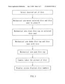
[0007]FIG. 1 is an operation flow chart of the present invention.
[0008]FIG. 2 illustrates an automatic dice shaking system in accordance with the present invention.
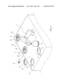
[0009]FIG. 3 is a schematic drawing showing the dice cup covered on one dice seat at one dice seat holder according to the present invention.
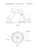
[0010]FIG. 4 is a schematic top view of a part of the present invention, showing the dice cup rotated relative to one dice seat at one dice seat holder according to the present invention.
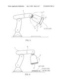
[0011]FIG. 5 is a schematic drawing showing a dice shaking action of the automatic dice shaking system in accordance with the present invention.
[0012]FIG. 6 is a schematic drawing showing a dice cup opened from the dice seat according to the present invention.
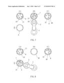
[0013]FIG. 7 is a schematic drawing of the present invention, showing the second set of dice selected.
[0014]FIG. 8 is a schematic drawing of the present invention, showing the second set of dice shifted to place D.
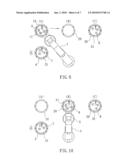
[0015]FIG. 9 is a schematic drawing of the present invention, showing the first set of dice at place A selected.
[0016]FIG. 10 is a schematic drawing of the present invention, showing the first set of dice shifted to place B.
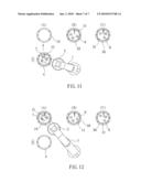
[0017]FIG. 11 is a schematic drawing of the present invention, showing the mechanical arm moved to the second set of dice at place D.
[0018]FIG. 12 is a schematic drawing of the present invention, showing the second set of dice shifted to place A.
DETAILED DESCRIPTION OF THE PREFERRED EMBODIMENT
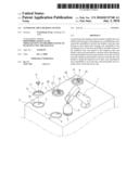
[0019]Referring to FIGS. 2˜6, an automatic dice shaking system in accordance with the present invention is shown mounted on a table, comprising a mechanical arm 1, a first dice seat holder 10, a second dice seat holder 20, a third dice seat holder 30, a fourth dice seat holder 4, a first dice seat 11, a second dice seat 21, and a third dice seat 31. The first through third dice seats 11, 21 and 31 hold a respective set of dice 6, 7 or 8. The mechanical arm 1 has a dice cup 2 coupled to the front end thereof, and controllable to move the dice cup 2 horizontally and vertically and to rotate the dice cup 2. Subject to the operation of the mechanical arm 1, the dice cup 2 can be selectively detachably attached to the dice seat 11, 21 or 31 and moved with the attached dice seat 11, 21 or 31 to shake the respective set of dice 6, 7 or 8.
[0020]Referring to FIG. 2 again, the dice cup 2 has an outer thread 3 extending around the periphery of the bottom side thereof. Each dice seat 11, 21 or 31 has an inner thread 13, 23 or 33 for engagement with the outer thread 3 of the dice cup 2, and at least one, for example, two locating rods 12 protruded from the periphery at two opposite sides. Each dice seat holder 10, 20, 30 or 4 has at least one, for example, two locating grooves 5 symmetrically disposed at two opposite sides corresponding to the locating rods 12 of each of the dice seats 11, 21 and 31. As shown in FIG. 3, the mechanical arm 1 is controlled to move the dice cup 2 to one dice seat 11, 21 or 31 at the dice seat holder 10, 20 or 30. At this time, the locating rods 12 of the dice seat 11, 21 or 31 are respectively positioned in the locating grooves 5 of the dice seat holder 10, 20 or 30. Thereafter, the mechanical arm 1 is controlled to rotate the dice cup 2, thereby threading the outer thread 3 into the inner thread 13, 23 or 33 of the dice seat 11, 21 or 31. After engagement between the dice cup 2 and the dice seat 11, 21 or 31. The mechanical arm 1 is controlled to life the dice cup 2 and the dice seat the dice seat 11, 21 or 31 from the dice seat holder 10, 20 or 30, and then to rotate the dice cup 2, thereby shaking the dice 6, 7 or 8 on the dice seat 11, 21 or 31. Thereafter, the mechanical arm 1 is controlled to move the dice cup 2 and the connected dice seat 11, 21 or 31 to the dice seat holder 10, 20 or 30, and to rotate the dice cup 2 in the reversed direction, disengaging the dice cup 2 from the dice seat 11, 21 or 31. Thereafter, the mechanical arm 1 is controlled to lift the dice cup 2, and therefore the number of each of the dice 6 is seen.
[0021]When playing the game, as shown in FIG. 1, assign one set of the dice 6, 7 or 8 on the dice seat 11, 21 or 31 for playing the game, for example, select the dice 6 on the dice seat 11. As shown in FIGS. 7˜12, control the mechanical arm 1 to fasten the dice cup 2 to the second dice seat 21 at place B (see FIG. 7), and then to carry the second dice seat 21 and the respective dice 7 to the fourth dice seat holder 4 at place D (see FIG. 8), and then to move the dice cup 2 to the first dice seat 11 carrying the dice 6 at place A (see FIG. 9), and then to carry the dice cup 2 with the first dice seat 11 and the dice 6 to the second dice seat holder 20 at place B (see FIG. 10), and then to move the dice cup 2 to the dice cup 2 to second dice seat 21 at place D (see FIG. 11) and to fasten the dice cup 2 to the second dice seat 21, and then to carry the dice cup 2 with the second dice seat 21 and the respective dice 7 to the first dice seat holder 10 at place A (see FIG. 10), finishing shift of the first set of dice 6 to place B. In the same manner, the third dice seat 31 with the third set of dice 8 can be shifted from place C to place B.
[0022]After shifting of the dice 6, 7 or 8 to place B, the mechanical arm 1 is controlled to fasten the dice cup 2 to the first dice seat 11 (see FIGS. 3 and 4), and then to move the dice cup 2 and the first dice seat 11, thereby shaking the dice 6 (see FIG. 5). Thereafter, the mechanical arm 1 is controlled to open the dice cup 1 from the first dice seat 11 (see the imaginary line in FIG. 4), and therefore the numbers of the dice 6 are seen. A digital camera (not shown) is controlled to take the picture of the dice 6, enabling a display screen (not shown) to display the numbers of the dice 6.
[0023]Although a particular embodiment of the invention has been described in detail for purposes of illustration, various modifications and enhancements may be made without departing from the spirit and scope of the invention. Accordingly, the invention is not to be limited except as by the appended claims.
Claims:
1. An automatic dice shaking system, comprising:a plurality of dice seat
holders arranged on a tabletop at different locations, each said dice
seat holder comprising a plurality of locating grooves;a plurality of
dice seats selectively attachable to said dice seat holders, each said
dice seat comprising an inner thread, and a plurality of locating rods
attachable to the locating grooves of one said dice seat holder to
prohibit rotation of the respective dice seat relative to the dice seat
holder to which the respective dice seat is attached. Each said dice seat
holding a respective set of dice;a dice cup connectable to one said dice
seat and movable with the connected dice seat away from said dice seat
holders to shake the respective set of dice, said dice cup comprising an
outer thread for threading into the inner thread of one said dice seat;
anda mechanical arm controllable to move said dice cup horizontally and
vertically and to rotate said device cup.Description:
BACKGROUND OF THE INVENTION
[0001]1. Field of the Invention
[0002]The present invention relates to dice game technology and more particularly, to an automatic dice shaking system, which can be controlled to select one of a number of sets of dice and to shake the selected set of dice automatically.
[0003]2. Description of the Related Art
[0004]Dice are small cubic objects used for generating random numbers for use in tabletop games. In one know dice game, players bet on the banker, and the banker puts the dice in a dice box and shakes the dice. After betting, the banker opens the dice cup and pay the dividens subject to the gambling result. However, performing the dice game in this manner has problems. Because dice shaking and dice cup opening actions are done manually, a dealer may control the points of the dice by means of a manipulation skill or have the expected points to appear by means of the control of the muscular strength of the hand shaking the dice. Therefore, a conventional manual dice shaking operation cannot prevent cheating.
SUMMARY OF THE INVENTION
[0005]Therefore, it is desirable to provide an automatic dice shaking system that automatically shakes the dice, avoiding cheating.
[0006]To achieve this and other objects of the present invention, the automatic dice shaking system comprises a plurality of dice seat holders arranged on a table top at different locations, each dice seat holder comprising a plurality of locating grooves; a plurality of dice seats selectively attachable to the dice seat holders, each dice seat comprising an inner thread, and a plurality of locating rods attachable to the locating grooves of one dice seat holder to prohibit rotation of the respective dice seat relative to the dice seat holder to which the respective dice seat is attached. Each dice seat holding a respective set of dice; a dice cup connectable to one dice seat and movable with the connected dice seat away from the dice seat holders to shake the respective set of dice, the dice cup comprising an outer thread for threading into the inner thread of one dice seat; and a mechanical arm controllable to move the dice cup horizontally and vertically and to rotate the device cup.
BRIEF DESCRIPTION OF THE DRAWINGS
[0007]FIG. 1 is an operation flow chart of the present invention.
[0008]FIG. 2 illustrates an automatic dice shaking system in accordance with the present invention.
[0009]FIG. 3 is a schematic drawing showing the dice cup covered on one dice seat at one dice seat holder according to the present invention.
[0010]FIG. 4 is a schematic top view of a part of the present invention, showing the dice cup rotated relative to one dice seat at one dice seat holder according to the present invention.
[0011]FIG. 5 is a schematic drawing showing a dice shaking action of the automatic dice shaking system in accordance with the present invention.
[0012]FIG. 6 is a schematic drawing showing a dice cup opened from the dice seat according to the present invention.
[0013]FIG. 7 is a schematic drawing of the present invention, showing the second set of dice selected.
[0014]FIG. 8 is a schematic drawing of the present invention, showing the second set of dice shifted to place D.
[0015]FIG. 9 is a schematic drawing of the present invention, showing the first set of dice at place A selected.
[0016]FIG. 10 is a schematic drawing of the present invention, showing the first set of dice shifted to place B.
[0017]FIG. 11 is a schematic drawing of the present invention, showing the mechanical arm moved to the second set of dice at place D.
[0018]FIG. 12 is a schematic drawing of the present invention, showing the second set of dice shifted to place A.
DETAILED DESCRIPTION OF THE PREFERRED EMBODIMENT
[0019]Referring to FIGS. 2˜6, an automatic dice shaking system in accordance with the present invention is shown mounted on a table, comprising a mechanical arm 1, a first dice seat holder 10, a second dice seat holder 20, a third dice seat holder 30, a fourth dice seat holder 4, a first dice seat 11, a second dice seat 21, and a third dice seat 31. The first through third dice seats 11, 21 and 31 hold a respective set of dice 6, 7 or 8. The mechanical arm 1 has a dice cup 2 coupled to the front end thereof, and controllable to move the dice cup 2 horizontally and vertically and to rotate the dice cup 2. Subject to the operation of the mechanical arm 1, the dice cup 2 can be selectively detachably attached to the dice seat 11, 21 or 31 and moved with the attached dice seat 11, 21 or 31 to shake the respective set of dice 6, 7 or 8.
[0020]Referring to FIG. 2 again, the dice cup 2 has an outer thread 3 extending around the periphery of the bottom side thereof. Each dice seat 11, 21 or 31 has an inner thread 13, 23 or 33 for engagement with the outer thread 3 of the dice cup 2, and at least one, for example, two locating rods 12 protruded from the periphery at two opposite sides. Each dice seat holder 10, 20, 30 or 4 has at least one, for example, two locating grooves 5 symmetrically disposed at two opposite sides corresponding to the locating rods 12 of each of the dice seats 11, 21 and 31. As shown in FIG. 3, the mechanical arm 1 is controlled to move the dice cup 2 to one dice seat 11, 21 or 31 at the dice seat holder 10, 20 or 30. At this time, the locating rods 12 of the dice seat 11, 21 or 31 are respectively positioned in the locating grooves 5 of the dice seat holder 10, 20 or 30. Thereafter, the mechanical arm 1 is controlled to rotate the dice cup 2, thereby threading the outer thread 3 into the inner thread 13, 23 or 33 of the dice seat 11, 21 or 31. After engagement between the dice cup 2 and the dice seat 11, 21 or 31. The mechanical arm 1 is controlled to life the dice cup 2 and the dice seat the dice seat 11, 21 or 31 from the dice seat holder 10, 20 or 30, and then to rotate the dice cup 2, thereby shaking the dice 6, 7 or 8 on the dice seat 11, 21 or 31. Thereafter, the mechanical arm 1 is controlled to move the dice cup 2 and the connected dice seat 11, 21 or 31 to the dice seat holder 10, 20 or 30, and to rotate the dice cup 2 in the reversed direction, disengaging the dice cup 2 from the dice seat 11, 21 or 31. Thereafter, the mechanical arm 1 is controlled to lift the dice cup 2, and therefore the number of each of the dice 6 is seen.
[0021]When playing the game, as shown in FIG. 1, assign one set of the dice 6, 7 or 8 on the dice seat 11, 21 or 31 for playing the game, for example, select the dice 6 on the dice seat 11. As shown in FIGS. 7˜12, control the mechanical arm 1 to fasten the dice cup 2 to the second dice seat 21 at place B (see FIG. 7), and then to carry the second dice seat 21 and the respective dice 7 to the fourth dice seat holder 4 at place D (see FIG. 8), and then to move the dice cup 2 to the first dice seat 11 carrying the dice 6 at place A (see FIG. 9), and then to carry the dice cup 2 with the first dice seat 11 and the dice 6 to the second dice seat holder 20 at place B (see FIG. 10), and then to move the dice cup 2 to the dice cup 2 to second dice seat 21 at place D (see FIG. 11) and to fasten the dice cup 2 to the second dice seat 21, and then to carry the dice cup 2 with the second dice seat 21 and the respective dice 7 to the first dice seat holder 10 at place A (see FIG. 10), finishing shift of the first set of dice 6 to place B. In the same manner, the third dice seat 31 with the third set of dice 8 can be shifted from place C to place B.
[0022]After shifting of the dice 6, 7 or 8 to place B, the mechanical arm 1 is controlled to fasten the dice cup 2 to the first dice seat 11 (see FIGS. 3 and 4), and then to move the dice cup 2 and the first dice seat 11, thereby shaking the dice 6 (see FIG. 5). Thereafter, the mechanical arm 1 is controlled to open the dice cup 1 from the first dice seat 11 (see the imaginary line in FIG. 4), and therefore the numbers of the dice 6 are seen. A digital camera (not shown) is controlled to take the picture of the dice 6, enabling a display screen (not shown) to display the numbers of the dice 6.
[0023]Although a particular embodiment of the invention has been described in detail for purposes of illustration, various modifications and enhancements may be made without departing from the spirit and scope of the invention. Accordingly, the invention is not to be limited except as by the appended claims.
User Contributions:
Comment about this patent or add new information about this topic:
| People who visited this patent also read: | |
| Patent application number | Title |
|---|---|
| 20140208753 | METHOD FOR ENERGY STORAGE TO UTILIZE INTERMITTENT RENEWABLE ENERGY AND LOW-VALUE ELECTRICITY FOR CO2 CAPTURE AND UTILIZATION |
| 20140208752 | METHOD AND APPARATUS OF PRODUCING AND UTILIZING THERMAL ENERGY IN A COMBINED HEAT AND POWER PLANT |
| 20140208751 | PROCESS FOR CONTROLLING A POWER TURBINE THROTTLE VALVE DURING A SUPERCRITICAL CARBON DIOXIDE RANKINE CYCLE |
| 20140208750 | METHODS FOR REDUCING WEAR ON COMPONENTS OF A HEAT ENGINE SYSTEM AT STARTUP |
| 20140208749 | CARBON DIOXIDE RECOVERY METHOD AND CARBON-DIOXIDE-RECOVERY-TYPE STEAM POWER GENERATION SYSTEM |
Images included with this patent application:
 |  |
 |  |
 |  |
 |  |
| Similar patent applications: | |
| Date | Title |
|---|---|
| 2013-04-25 | Automatic card shuffler with pivotal card weight and divider gate |
| 2010-02-11 | Information processing system |
| 2011-01-27 | Self-contained dice shaker system |
| 2012-03-15 | Self-contained dice shaker system |
| 2009-01-15 | Online gaming system |
| New patent applications in this class: | |
| Date | Title |
|---|---|
| 2011-11-03 | Game apparatus and method of manufacturing same |
| 2010-06-17 | Game apparatus and method of manufacturing same |
| New patent applications from these inventors: | |
| Date | Title |
|---|---|
| 2016-02-04 | Multi-circular-track ball-drawing device |
| 2016-02-04 | Circular-track ball-drawing device |
| 2015-12-17 | Wireless communication system for human rescue |
| 2015-10-01 | Playing card conduction structure |
| Top Inventors for class "Amusement devices: games" | |
| Rank | Inventor's name |
|---|---|
| 1 | Attila Grauzer |
| 2 | Peter Krenn |
| 3 | Ronald R. Swanson |
| 4 | Kyle Bateman |
| 5 | Feraidoon Bourbour |