Patent application title: HYDROCARBON RESERVOIR TREATMENT METHOD WITH HYDROCARBONS
Inventors:
John Edwards (Calgary, CA)
Assignees:
SYNOIL FLUIDS HOLDINGS INC.
IPC8 Class: AE21B4316FI
USPC Class:
166268
Class name: Wells processes distinct, separate injection and producing wells
Publication date: 2010-06-03
Patent application number: 20100132942
ent fluid is made recyclable by introducing a
laminar flow enhancer into the fluid, resulting in a formulation called
Slick Oil® hydrocarbon fluid. A method of using a fluid in the
treatment of a hydrocarbon reservoir is disclosed. A hydrocarbon fluid is
injected into the hydrocarbon reservoir, the hydrocarbon fluid comprising
hydrocarbons and a hydrophobic laminar flow enhancer. The hydrocarbon
fluid is recovered from the hydrocarbon reservoir. The recovered
hydrocarbon fluid is then cleaned by removing contaminants from the
recovered hydrocarbon fluid that have been introduced into the
hydrocarbon fluid from the hydrocarbon reservoir. The hydrocarbon fluid
is then re-used by injecting the cleaned and recovered hydrocarbon fluid
into at least one subsequent hydrocarbon reservoir. Proppant carrying
abilities of a hydrocarbon fracturing fluid are enhanced by introducing a
laminar flow enhancer into the fluid, resulting in a formulation called
Slick Oil® hydrocarbon fluid.Claims:
1. A method of using a fluid in the treatment of a hydrocarbon reservoir,
the method comprising:injecting a hydrocarbon fluid into the hydrocarbon
reservoir, the hydrocarbon fluid comprising hydrocarbons and a
hydrophobic laminar flow enhancer;recovering the hydrocarbon fluid from
the hydrocarbon reservoir;cleaning the recovered hydrocarbon fluid by
removing contaminants from the recovered hydrocarbon fluid that have been
introduced into the hydrocarbon fluid from the hydrocarbon reservoir;
andre-using the hydrocarbon fluid by injecting the cleaned and recovered
hydrocarbon fluid into at least one subsequent hydrocarbon reservoir.
2. The method of claim 1 in which the at least one subsequent hydrocarbon reservoir comprises the hydrocarbon reservoir.
3. The method of claim 1 in which the at least one subsequent hydrocarbon reservoir comprises a second hydrocarbon reservoir.
4. The method of claim 1 further comprising applying pressure to the hydrocarbon fluid injected into the hydrocarbon reservoir.
5. The method of claim 4 in which the pressure is sufficient to cause fracturing of the hydrocarbon reservoir.
6. The method of claim 1 in which re-using further comprises applying pressure to the cleaned and recovered hydrocarbon fluid injected into the subsequent hydrocarbon reservoir.
7. The method of claim 6 in which the pressure applied to the cleaned and recovered hydrocarbon fluid injected into the subsequent hydrocarbon reservoir is sufficient to cause fracturing of the subsequent hydrocarbon reservoir.
8. The method of claim 1 in which removing contaminants comprises removing solid particles.
9. The method of claim 8 in which removing solid particles comprises filtering.
10. The method of claim 9 in which filtering of the recovered hydrocarbon fluid comprises removing particles greater than 1 μm in diameter.
11. The method of claim 1 in which removing contaminants comprises heating the recovered hydrocarbon fluid to remove volatile components.
12. The method of claim 11 in which sufficient volatile components are removed to cause the recovered hydrocarbon fluid to have a flash point greater than 10.degree. C. and a Reid vapour pressure of at least 2 psi.
13. The method of claim 1 in which removing contaminants comprises applying a vacuum to the recovered hydrocarbon fluid to remove volatile components.
14. The method of claim 1 in which removing contaminants comprises removing water from the recovered hydrocarbon fluid.
15. The method of claim 14 in which removing water comprises one or more of decanting, centrifuging, skimming, and drying.
16. The method of claim 1 in which the hydrophobic laminar flow enhancer comprises a polymerized hydrocarbon.
17. The method of claim 1 in which the hydrocarbon fluid is initially injected into the hydrocarbon reservoir with proppant.
18. The method of claim 1 in which the hydrophobic laminar flow enhancer is present in an amount of less than 1% by weight of the hydrocarbon fluid.
19. The method of claim 1 in which the hydrocarbon fluid is injected into the hydrocarbon reservoir along with a drive fluid.
20. The method of claim 19 in which the drive fluid comprises carbon dioxide, liquefied petroleum gas, or nitrogen.
21. The method of claim 1 in which hydrophobic laminar flow enhancer is added to the recovered and cleaned hydrocarbon fluid before or during re-use of the recovered and cleaned hydrocarbon fluid.
22-29. (canceled)
30. The method of claim 1 in which the hydrocarbon fluid excludes a is free of gelling agent.
31. The method of claim 1 in which the hydrocarbon fluid excludes is free of liquefied petroleum gas.
32. The method of claim 1 in which the hydrocarbon fluid comprises liquefied petroleum gas.
33-36. (canceled)
37. A method of using a fluid in the treatment of a hydrocarbon reservoir, the method comprising:injecting a hydrocarbon fluid into the hydrocarbon reservoir, the hydrocarbon fluid comprising liquefied petroleum gas and a laminar flow enhancer; andapplying pressure to the hydrocarbon fluid injected into the hydrocarbon reservoir.
38. The method of claim 37 in which the pressure applied to the hydrocarbon fluid is sufficient to cause fracturing of the hydrocarbon reservoir.
39. The method of claim 37 in which the hydrocarbon fluid further comprises C6+ hydrocarbon fluid.
40. The method of claim 39 in which the C6+ hydrocarbon fluid is combined with laminar flow enhancer and then mixed with liquefied petroleum gas prior to injection into the well.
41-48. (canceled)
49. The method of claim 1 in which the hydrocarbons comprise liquefied petroleum gas.Description:
TECHNICAL FIELD
[0001]Treatment of hydrocarbon reservoirs to enhance production.
BACKGROUND
[0002]Production may be increased from a hydrocarbon reservoir by fracturing the reservoir with hydraulic fluid. Water is often used as the hydraulic fluid since it is inexpensive. However, water tends to damage, and may reduce production from, hydrocarbon reservoirs. Hydrocarbon fluids may also be used for hydraulic fracturing since hydrocarbon fluids tend to cause less formation damage, but hydrocarbon fluids are considerably more expensive than water in many locations, such as for example North America. An inexpensive method of fracturing a hydrocarbon reservoir with hydrocarbon is required.
[0003]Fractures caused by fracturing may be kept open by introducing particulates known as proppant into the hydrocarbon reservoir along with the hydraulic fluid. Liquefied petroleum gas may be advantageously used as the hydraulic fluid, but causing the liquefied petroleum gas to carry sufficient proppant may introduce other problems, such as recovery and disposal of a gellant used to increase the viscosity of the hydraulic fluid. A novel method of fracturing a hydrocarbon reservoir with hydrocarbon fluid is required.
SUMMARY
[0004]In an embodiment, a hydrocarbon well treatment fluid is made recyclable by introducing a laminar flow enhancer into the fluid, resulting in a formulation called Slick Oil® hydrocarbon fluid.
[0005]In a further embodiment, proppant carrying abilities of a hydrocarbon fracturing fluid are enhanced by introducing a laminar flow enhancer into the fluid, resulting in a formulation called Slick Oil® hydrocarbon fluid.
[0006]Also, a method of using a fluid in the treatment of a hydrocarbon reservoir is disclosed. A hydrocarbon fluid is injected into the hydrocarbon reservoir, the hydrocarbon fluid comprising hydrocarbons and a hydrophobic laminar flow enhancer. The hydrocarbon fluid is recovered from the hydrocarbon reservoir. The recovered hydrocarbon fluid is then cleaned by removing contaminants from the recovered hydrocarbon fluid that have been introduced into the hydrocarbon fluid from the hydrocarbon reservoir. The hydrocarbon fluid is then re-used by injecting the cleaned and recovered hydrocarbon fluid into at least one subsequent hydrocarbon reservoir.
[0007]A method of using a fluid in the treatment of a hydrocarbon reservoir is also disclosed. A hydrocarbon fluid is injected into the hydrocarbon reservoir, the hydrocarbon fluid comprising hydrocarbons and a hydrophobic laminar flow enhancer. The hydrocarbon fluid is then recovered from the hydrocarbon reservoir.
[0008]A method is also disclosed comprising cleaning a hydrocarbon fluid that has been injected into and subsequently recovered from a hydrocarbon reservoir during a treatment of the hydrocarbon reservoir, the cleaning comprising removing contaminants from the recovered hydrocarbon fluid that have been introduced into the hydrocarbon fluid from the hydrocarbon reservoir, the hydrocarbon fluid comprising hydrocarbons and a hydrophobic laminar flow enhancer.
[0009]A method of re-using a hydrocarbon fluid previously used in a treatment of a hydrocarbon reservoir during which the hydrocarbon fluid was injected into and subsequently recovered from the hydrocarbon reservoir and cleaned to remove contaminants introduced into the hydrocarbon fluid from the hydrocarbon reservoir, is also disclosed. The method comprises injecting the cleaned and recovered hydrocarbon fluid into at least one subsequent hydrocarbon reservoir, the hydrocarbon fluid comprising hydrocarbons and a hydrophobic laminar flow enhancer.
[0010]In some embodiments of the methods disclosed herein, the hydrocarbon fluid excludes liquefied petroleum gas. In other embodiments of the methods disclosed herein, the hydrocarbon fluid comprises liquefied petroleum gas.
[0011]In another embodiment, there is provided apparatus for treating hydrocarbon fluid recovered from a well.
[0012]A method of using a fluid in the treatment of a hydrocarbon reservoir is also disclosed. A hydrocarbon fluid is injected into the hydrocarbon reservoir, the hydrocarbon fluid comprising liquefied petroleum gas and a laminar flow enhancer. Pressure is applied to the hydrocarbon fluid injected into the hydrocarbon reservoir.
[0013]These and other aspects of the device and method are set out in the claims, which are incorporated here by reference.
BRIEF DESCRIPTION OF THE FIGURES
[0014]Embodiments will now be described with reference to the figures, in which like reference characters denote like elements, by way of example, and in which:
[0015]FIG. 1 is a side elevation view of a treatment system designed to carry out the methods disclosed herein.
[0016]FIG. 2 is a flow diagram of a method of using a fluid in the treatment of a hydrocarbon reservoir.
[0017]FIG. 3 is a flow diagram of a method of using a fluid in the treatment of a hydrocarbon reservoir.
[0018]FIG. 4 is a flow diagram of a method of cleaning a hydrocarbon fluid that has been injected into and subsequently recovered from a hydrocarbon reservoir during a treatment of the hydrocarbon reservoir.
[0019]FIG. 5 is a flow diagram of a method of re-using a hydrocarbon fluid previously used in a treatment of a hydrocarbon reservoir.
[0020]FIG. 6 is a flow diagram of a method of using a fluid in the treatment of a hydrocarbon reservoir.
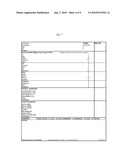
[0021]FIG. 7 is a metals analysis of a sample of hydrocarbon fluid with UFV-100.
DETAILED DESCRIPTION
[0022]Immaterial modifications may be made to the embodiments described here without departing from what is covered by the claims.
[0023]Laminar flow enhancers may be added to oil, in order to allow the oil to go down a pipeline faster and easier. The flow enhancer operates by allowing the oil to move in a more laminar flow, thus reducing turbulence. These characteristics reduce the drag and friction between the oil and the pipeline, thus reducing the pressure required to pump the oil. Laminar flow enhancers may be polymers, for example polymerized hydrocarbons, thus adding viscosity to the hydrocarbon fluid, which reduces the turbulence induced as the fluid flows. Reductions in fluid friction of 50 to 60% are possible. Laminar flow enhancers tend to lubricate the oil, making the oil travel in sheets as the polymers slide in relation to one another, which results in a reduction or elimination of turbulent flow. Examples of hydrophobic flow enhancers include OFR-2 by Weatherford.
[0024]The laminar flow enhancer used in the embodiments herein may be hydrophobic. Hydrophilic laminar flow enhancers are less desirable, as they tend to absorb additional water from the formation, thus increasing the cost of cleaning the recovered hydrocarbon fluid. In addition, hydrophilic enhancers may plate out in the formation alongside formation water, thus plugging the pores of the formation. In some embodiments, the hydrophobic laminar flow enhancers disclosed herein do not plate out in the well or formation. In addition, the hydrophobic laminar flow enhancer may be a non-emulsifier, thus allowing any water absorbed into the hydrocarbon fluid from the hydrocarbon reservoir to be easily removable. The hydrophobic laminar flow enhancer may be used in very low concentration, such as less than 0.5-1% for example. At sufficiently low concentrations, the enhancer is not required to be listed on the MSDS of the fluid. In some embodiments, the hydrophobic flow enhancer may be easily removable from the hydrocarbon fluid. An example of a hydrocarbon fluid that has all of these characteristics is Slick Oil® fluid supplied by SynOil Fluids of Calgary, Alberta, Canada. Slick Oil® fluid will absorb very little measurable water during a downhole treatment. Examples of suitable hydrophobic flow enhancers include those disclosed in U.S. Pat. No. 6,395,852, and OFR-2 (Weatherford). In some embodiments, the hydrophobic laminar flow enhancer comprises a friction reducer. An example of such a hydrophobic laminar flow enhancer is EC6507A, made by Nalco.
[0025]A further embodiment of a hydrophobic flow enhancer that comprises a friction reducer is UFV-100, available from Uniquem Inc., 240 Everwillow Green SW, Calgary, AB, T2Y 4V9. UFV-100 is advantageous because it is imparts additional viscosity to the hydrocarbon fluid. UFV-100 is shown in the Table 1 below as being added in, for example, amounts of 0.5 to 5.5 liters/m3 of the hydrocarbon fluid to get sufficient viscosity to carry proppant. In Table 1, the frac oils (hydrocarbon fluid) used were obtained from Synoil fluids in Calgary, AB. Referring to FIG. 7, a metals analysis of a sample of hydrocarbon fluid with UFV-100 demonstrates that UFV-100 contains little or no phosphorus, which is known to cause fouling issues in refineries. Hydrocarbon frac fluids with UFV-100 may filter easily through 5 micron filters.
TABLE-US-00001 TABLE 1 Viscosities of hydraulic frac fluid comprising UFV-100 Concentration Viscosity Viscosity Frac oil DG1 (L/m3) (centipoise) (centipoise) TG740 4 6 6 SF770 5.5 5 4 SF790 3.5 5 4 SF800 2.5 5 6 SF820 1.5 5 6 SF830 0.5 4 4 SF840 0.5 8 8 SF860 0.5 16 11
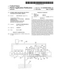
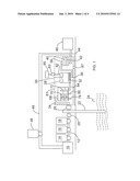
[0026]Referring to FIG. 1, an exemplary system is illustrated for carrying out the embodiments of the methods disclosed herein. The system illustrated is a general schematic, and a skilled worker will understand that additional components that are not shown may be required to implement the system. The illustrated components are for illustration only, and therefore are not to scale. Referring to FIG. 2, a method of using a fluid in the treatment of a hydrocarbon reservoir 24 is illustrated.
[0027]Referring to FIG. 1, in a stage 50 (shown in FIG. 2), a hydrocarbon fluid is injected into the hydrocarbon reservoir 24, the hydrocarbon fluid comprising hydrocarbons and a hydrophobic laminar flow enhancer. In FIG. 1, this stage may be accomplished as follows. Hydrocarbon fluid is initially contained within a reservoir 10. Reservoir 10 may be, for example, a tanker truck or a large vessel. The hydrocarbon fluid is pumped from reservoir 10 down line 12, where various chemicals may be added to the fluid. In some embodiments, the hydrocarbon fluid is stored in reservoir 10 with the hydrophobic laminar flow enhancer, and thus no chemicals may need to be added. In the system illustrated, hydrophobic flow enhancer may be added via an enhancer addition system 14. Other components may be added as well, such as gelling agent and proppant, from addition systems 16 and 18, respectively. The addition systems may be, for example, hoppers. Once the hydrocarbon fluid is prepared and ready, a high pressure pump 20 injects the hydrocarbon fluid down a well 22 and into hydrocarbon reservoir 24. The specifics of fracturing treatments such as this are well known, and need not be described here. In some embodiments, such as during a fracturing treatment, the method further comprises applying pressure to the hydrocarbon fluid injected into the hydrocarbon reservoir 24. The pressure may be sufficient to cause fracturing of the hydrocarbon reservoir. In some embodiments (not shown), the hydrocarbon fluid is injected into the hydrocarbon reservoir along with a drive fluid, for example comprising carbon dioxide, LPG, or nitrogen.
[0028]In a stage 52 (shown in FIG. 2), the hydrocarbon fluid is recovered from the hydrocarbon reservoir 24. In FIG. 1, this stage may be accomplished as follows. The spent hydrocarbon fluid is returned from hydrocarbon reservoir 24 through well 22, using a pump 26 for example. The recovered hydrocarbon fluid may then be stored, processed for re-use, sold, or disposed of. In some embodiments, the hydrocarbon fluid is at least partially recovered.
[0029]In a stage 54 (shown in FIG. 2), the recovered hydrocarbon fluid is then cleaned by removing contaminants from the recovered hydrocarbon fluid that have been introduced into the hydrocarbon fluid from the hydrocarbon reservoir 24. The contaminants may comprise at least one of water, volatile hydrocarbons and fine particulates. In FIG. 1, this stage may be accomplished as follows. The hydrocarbon fluid may be passed through a line 34 into a water separation unit 68. Unit 68 may be any type of water separation unit. Water may comprise one of the contaminants that is introduced downhole into the hydrocarbon fluid. In the embodiment illustrated, unit 68 has several weirs 70, 72, designed to allow water to collect at the bottom of each compartment defined by the weirs, in order that the water may be removed from the hydrocarbon fluid via lines 78, 80. In the initial compartment, water 74 and hydrocarbon 76 layers are illustrated for reference, although the relative amounts of water and hydrocarbon are not to scale. In some embodiments, the cleaning stage 54 may also comprise removing water through one or more of decanting, centrifuging, skimming, and drying.
[0030]De-watered hydrocarbon fluid is then passed from unit 68 into line 84 into a vapor removal unit 28. Unit 28 may be designed to remove volatile contaminants by for example heating the recovered hydrocarbon fluid. In some embodiments, sufficient volatile components are removed to cause the recovered hydrocarbon fluid to have a flash point greater than 10° C. and a Reid vapor pressure of at least 2 psi. In some embodiments, the Reid vapor pressure is 4 kPa. In other embodiments, sufficient volatiles are removed to meet the local regulations as required. This may be accomplished by heating the hydrocarbon fluid (indicated by reference numeral 30) using heating coil 32 as shown, which may for example be any of various types of heaters, such as a conduit carrying heated fluid. An exemplary treatment may comprise heating the recovered hydrocarbon fluid to 80 degrees C. for 15 minutes with a ramp up and ramp down. This may remove any C5 and under hydrocarbons, for example. In some embodiments, a vacuum may be applied, via line 82 for example, to the recovered hydrocarbon fluid to remove the volatile components. The line 82 may be connected to a pump or other vacuum source 83, and the pump or other vacuum source 83 may pump vapors out to a vapor disposal unit 85, such as a flare or vapor recovery system.
[0031]Once sufficient volatiles are removed, the partially cleaned hydrocarbon fluid is then passed via line 36 into a solids removal unit 38. Unit 38 may comprise at least one filter 42, for example, for removing solid particles. The filtering of the recovered hydrocarbon fluid may comprise removing particles greater than 1 μm in diameter, for example. The filtered solid particles are illustrated by reference numeral 40 for example.
[0032]In some embodiments, the oil-water separator, the vapor removal unit and the solids removal unit are connected together for sequential processing of the hydrocarbon fluid to clean the hydrocarbon fluid for subsequent re-use. It should be understood that, during the cleaning stage, the position of units 68, 28, and 38 in the process line may be interchanged or switched. For example, it may be beneficial to filter the hydrocarbon fluid prior to removing volatiles and water. In addition, other cleaning stages or units may be added as desired. Prior to cleaning, the cleaned and recovered hydrocarbon fluid may be passed from unit 38 via line 44 into, for example, a reservoir 46 for storage. In other embodiments, the cleaned and recovered hydrocarbon fluid may be passed back into reservoir 10 via line 49 for example. In further embodiments, the cleaned and recovered hydrocarbon fluid may be passed to a sales line. In some embodiments, the hydrocarbon fluid is at least partially cleaned. In addition, the units 68, 28 and 38 may be mounted together as a unit 81 for example on a trailer bed or skid 87 for mobile operation.
[0033]In a stage 56 (shown in FIG. 2), the hydrocarbon fluid is re-used by injecting the cleaned and recovered hydrocarbon fluid into at least one subsequent hydrocarbon reservoir. In FIG. 1, this stage may be accomplished as follows. The cleaned and recovered hydrocarbon fluid is passed, via line 49, into reservoir 10, where it is prepared and injected into hydrocarbon reservoir 24 in a fashion similar to stage 50. In this way, the at least one subsequent hydrocarbon reservoir comprises the hydrocarbon reservoir 24. In other embodiments (not illustrated), the at least one subsequent hydrocarbon reservoir comprises a second hydrocarbon reservoir. Re-using may further comprise applying pressure to the cleaned and recovered hydrocarbon fluid injected into the subsequent hydrocarbon reservoir, in a fashion similar to stage 50. In these embodiments, the pressure applied to the cleaned and recovered hydrocarbon fluid injected into the subsequent hydrocarbon reservoir may be sufficient to cause fracturing of the subsequent hydrocarbon reservoir. Hydrophobic laminar flow enhancer may be added to the recovered and cleaned hydrocarbon fluid before or during re-use of the recovered and cleaned hydrocarbon fluid, via addition units 48 or 14, for example. In some embodiments, the hydrocarbon fluid is at least partially re-used. In some embodiments, the hydrocarbon fluid is re-used in at least two different wells or reservoirs.
[0034]As disclosed above, in some embodiments, gelling agents may be used in the hydrocarbon fluid. However, in other embodiments, the hydrocarbon fluid excludes a gelling agent. Gelling agents tend to be hard to remove from hydrocarbon fluids, and may decrease the value of the hydrocarbon fluid when present. Spent gelling agents also present a clean-up cost required to make the hydrocarbon fluid ready for sale or further fracturing treatments. Gelling agents are also typically used in large concentrations, and absorb water while in the formation, further increasing clean-up costs. The presence of gelling agents, namely phosphorous containing gelling agents, have also been identified as the causes of extensive complications in downstream facilities, where certain varieties are known to plug distillation trays and shut down refineries.
[0035]The hydrophobic laminar flow enhancer allows large amounts of proppant to be carried downhole in the hydrocarbon fluid, and thus a gelling agent may not be required. This represents a huge technical advantage, namely when LPG fluids are used, because this overcomes the limitation of the relatively small proppant volumes usable with conventional LPG systems, as the amount of proppant that can be pumped with the LPG is greatly increased.
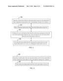
[0036]Referring to FIG. 3, a further method of using a fluid in the treatment of a hydrocarbon reservoir is disclosed. Referring to FIG. 1, in a stage 58 (shown in FIG. 3), a hydrocarbon fluid is injected into the hydrocarbon reservoir 24, the hydrocarbon fluid comprising hydrocarbons and a hydrophobic laminar flow enhancer. This stage may be carried out in a fashion similar to stage 50, for example. In a stage 60 (shown in FIG. 3), the hydrocarbon fluid from is recovered from the hydrocarbon reservoir 24. This stage may be carried out in a fashion similar to stage 52, for example. This method may further comprise, for example, a further stage similar to stage 54 comprising cleaning the recovered hydrocarbon fluid by removing contaminants from the recovered hydrocarbon fluid that have been introduced into the hydrocarbon fluid from the hydrocarbon reservoir. In some embodiments, the hydrocarbon fluid is to be re-used by injection of the cleaned and recovered hydrocarbon fluid into at least one subsequent hydrocarbon reservoir.
[0037]Referring to FIG. 4, a further method is illustrated. Referring to FIG. 1, in a stage 62 (shown in FIG. 4), a hydrocarbon fluid is cleaned. The hydrocarbon fluid has been previously injected into and subsequently recovered from hydrocarbon reservoir 24 during a treatment of the hydrocarbon reservoir 24. The cleaning comprises removing contaminants from the recovered hydrocarbon fluid that have been introduced into the hydrocarbon fluid from the hydrocarbon reservoir 24. The hydrocarbon fluid comprises hydrocarbons and a hydrophobic laminar flow enhancer. The treatment of the hydrocarbon reservoir 24 may be a fracturing operation. This method may further comprise injecting the cleaned and recovered hydrocarbon fluid into at least one subsequent hydrocarbon reservoir, for example. Further, in some embodiments the hydrocarbon fluid is to be re-used by injection of the cleaned and recovered hydrocarbon fluid into at least one subsequent hydrocarbon reservoir. Stage 62 may be carried out in a fashion similar to stage 54.
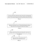
[0038]Referring to FIG. 5, a method of re-using a hydrocarbon fluid previously used in a treatment of a hydrocarbon reservoir is illustrated. During the treatment, the hydrocarbon fluid had been injected into and subsequently recovered from the hydrocarbon reservoir and cleaned to remove contaminants introduced into the hydrocarbon fluid from the hydrocarbon reservoir. Referring to FIG. 1, in a stage 64 (shown in FIG. 5), the cleaned and recovered hydrocarbon fluid is injected into at least one subsequent hydrocarbon reservoir, the hydrocarbon fluid comprising hydrocarbons and a hydrophobic laminar flow enhancer. Stage 64 may be carried out in a fashion similar to stage 56.
[0039]In some embodiments, the hydrocarbon fluid excludes liquefied petroleum gas. Excluding may refer to there being less than 1% of the excluded component present. In other embodiments, excluding may refer to there being less than 0.1 or 0.01% of the excluded component present. In other embodiments, the hydrocarbon fluid comprises liquefied petroleum gas. LPG is advantageous, since it may be vaporized and easily removed from hydrocarbon reservoir 24 during treatment.
[0040]Referring to FIG. 6, a method of using a fluid in the treatment of a hydrocarbon reservoir is also disclosed. Referring to FIG. 1, in stage 90 (shown in FIG. 6), a hydrocarbon fluid is injected into the hydrocarbon reservoir 24, the hydrocarbon fluid comprising liquefied petroleum gas and a laminar flow enhancer. The laminar flow enhancer may be present in an amount of less than 1% by weight of the hydrocarbon fluid, for example. The hydrocarbon fluid may further comprise C6+ hydrocarbon fluid. In some embodiments, the C6+ hydrocarbon fluid is combined with laminar flow enhancer and then mixed with liquefied petroleum gas prior to injection into the well. Proppant may be added to the C6+ hydrocarbon fluid prior to mixing with liquefied petroleum gas. In some embodiments, the laminar flow enhancer is hydrophobic. The hydrocarbon fluid may be injected into the well along with a drive fluid. In stage 92 (shown in FIG. 6), pressure is applied to the hydrocarbon fluid injected into the hydrocarbon reservoir 24.
[0041]In some embodiments, the fracture treatment may combine a hydrocarbon fluid excluding LPG and a hydrocarbon fluid comprising LPG. For example, the treatment may combine a gelled LPG stream with proppant and a non-gelled stabilized hydrocarbon liquid with proppant which may be friction reduced. Friction reduction chemicals may be purchased commercially.
[0042]It should be understood that the methods disclosed herein may have various steps added to them, for example, adding repetition steps. For further example, the method disclosed in FIG. 4 may have the steps of stage 50, 52, and 54 added to it. For further example, the method illustrated in FIG. 6 may further comprise recovering, cleaning and re-using the hydrocarbon fluid. In another example, transport and processing steps may be added. In some embodiments, the methods disclosed herein may be applied to an unconventional tight gas reservoir.
[0043]In the claims, the word "comprising" is used in its inclusive sense and does not exclude other elements being present. The indefinite article "a" before a claim feature does not exclude more than one of the feature being present. Each one of the individual features described here may be used in one or more embodiments and is not, by virtue only of being described here, to be construed as essential to all embodiments as defined by the claims.
Claims:
1. A method of using a fluid in the treatment of a hydrocarbon reservoir,
the method comprising:injecting a hydrocarbon fluid into the hydrocarbon
reservoir, the hydrocarbon fluid comprising hydrocarbons and a
hydrophobic laminar flow enhancer;recovering the hydrocarbon fluid from
the hydrocarbon reservoir;cleaning the recovered hydrocarbon fluid by
removing contaminants from the recovered hydrocarbon fluid that have been
introduced into the hydrocarbon fluid from the hydrocarbon reservoir;
andre-using the hydrocarbon fluid by injecting the cleaned and recovered
hydrocarbon fluid into at least one subsequent hydrocarbon reservoir.
2. The method of claim 1 in which the at least one subsequent hydrocarbon reservoir comprises the hydrocarbon reservoir.
3. The method of claim 1 in which the at least one subsequent hydrocarbon reservoir comprises a second hydrocarbon reservoir.
4. The method of claim 1 further comprising applying pressure to the hydrocarbon fluid injected into the hydrocarbon reservoir.
5. The method of claim 4 in which the pressure is sufficient to cause fracturing of the hydrocarbon reservoir.
6. The method of claim 1 in which re-using further comprises applying pressure to the cleaned and recovered hydrocarbon fluid injected into the subsequent hydrocarbon reservoir.
7. The method of claim 6 in which the pressure applied to the cleaned and recovered hydrocarbon fluid injected into the subsequent hydrocarbon reservoir is sufficient to cause fracturing of the subsequent hydrocarbon reservoir.
8. The method of claim 1 in which removing contaminants comprises removing solid particles.
9. The method of claim 8 in which removing solid particles comprises filtering.
10. The method of claim 9 in which filtering of the recovered hydrocarbon fluid comprises removing particles greater than 1 μm in diameter.
11. The method of claim 1 in which removing contaminants comprises heating the recovered hydrocarbon fluid to remove volatile components.
12. The method of claim 11 in which sufficient volatile components are removed to cause the recovered hydrocarbon fluid to have a flash point greater than 10.degree. C. and a Reid vapour pressure of at least 2 psi.
13. The method of claim 1 in which removing contaminants comprises applying a vacuum to the recovered hydrocarbon fluid to remove volatile components.
14. The method of claim 1 in which removing contaminants comprises removing water from the recovered hydrocarbon fluid.
15. The method of claim 14 in which removing water comprises one or more of decanting, centrifuging, skimming, and drying.
16. The method of claim 1 in which the hydrophobic laminar flow enhancer comprises a polymerized hydrocarbon.
17. The method of claim 1 in which the hydrocarbon fluid is initially injected into the hydrocarbon reservoir with proppant.
18. The method of claim 1 in which the hydrophobic laminar flow enhancer is present in an amount of less than 1% by weight of the hydrocarbon fluid.
19. The method of claim 1 in which the hydrocarbon fluid is injected into the hydrocarbon reservoir along with a drive fluid.
20. The method of claim 19 in which the drive fluid comprises carbon dioxide, liquefied petroleum gas, or nitrogen.
21. The method of claim 1 in which hydrophobic laminar flow enhancer is added to the recovered and cleaned hydrocarbon fluid before or during re-use of the recovered and cleaned hydrocarbon fluid.
22-29. (canceled)
30. The method of claim 1 in which the hydrocarbon fluid excludes a is free of gelling agent.
31. The method of claim 1 in which the hydrocarbon fluid excludes is free of liquefied petroleum gas.
32. The method of claim 1 in which the hydrocarbon fluid comprises liquefied petroleum gas.
33-36. (canceled)
37. A method of using a fluid in the treatment of a hydrocarbon reservoir, the method comprising:injecting a hydrocarbon fluid into the hydrocarbon reservoir, the hydrocarbon fluid comprising liquefied petroleum gas and a laminar flow enhancer; andapplying pressure to the hydrocarbon fluid injected into the hydrocarbon reservoir.
38. The method of claim 37 in which the pressure applied to the hydrocarbon fluid is sufficient to cause fracturing of the hydrocarbon reservoir.
39. The method of claim 37 in which the hydrocarbon fluid further comprises C6+ hydrocarbon fluid.
40. The method of claim 39 in which the C6+ hydrocarbon fluid is combined with laminar flow enhancer and then mixed with liquefied petroleum gas prior to injection into the well.
41-48. (canceled)
49. The method of claim 1 in which the hydrocarbons comprise liquefied petroleum gas.
Description:
TECHNICAL FIELD
[0001]Treatment of hydrocarbon reservoirs to enhance production.
BACKGROUND
[0002]Production may be increased from a hydrocarbon reservoir by fracturing the reservoir with hydraulic fluid. Water is often used as the hydraulic fluid since it is inexpensive. However, water tends to damage, and may reduce production from, hydrocarbon reservoirs. Hydrocarbon fluids may also be used for hydraulic fracturing since hydrocarbon fluids tend to cause less formation damage, but hydrocarbon fluids are considerably more expensive than water in many locations, such as for example North America. An inexpensive method of fracturing a hydrocarbon reservoir with hydrocarbon is required.
[0003]Fractures caused by fracturing may be kept open by introducing particulates known as proppant into the hydrocarbon reservoir along with the hydraulic fluid. Liquefied petroleum gas may be advantageously used as the hydraulic fluid, but causing the liquefied petroleum gas to carry sufficient proppant may introduce other problems, such as recovery and disposal of a gellant used to increase the viscosity of the hydraulic fluid. A novel method of fracturing a hydrocarbon reservoir with hydrocarbon fluid is required.
SUMMARY
[0004]In an embodiment, a hydrocarbon well treatment fluid is made recyclable by introducing a laminar flow enhancer into the fluid, resulting in a formulation called Slick Oil® hydrocarbon fluid.
[0005]In a further embodiment, proppant carrying abilities of a hydrocarbon fracturing fluid are enhanced by introducing a laminar flow enhancer into the fluid, resulting in a formulation called Slick Oil® hydrocarbon fluid.
[0006]Also, a method of using a fluid in the treatment of a hydrocarbon reservoir is disclosed. A hydrocarbon fluid is injected into the hydrocarbon reservoir, the hydrocarbon fluid comprising hydrocarbons and a hydrophobic laminar flow enhancer. The hydrocarbon fluid is recovered from the hydrocarbon reservoir. The recovered hydrocarbon fluid is then cleaned by removing contaminants from the recovered hydrocarbon fluid that have been introduced into the hydrocarbon fluid from the hydrocarbon reservoir. The hydrocarbon fluid is then re-used by injecting the cleaned and recovered hydrocarbon fluid into at least one subsequent hydrocarbon reservoir.
[0007]A method of using a fluid in the treatment of a hydrocarbon reservoir is also disclosed. A hydrocarbon fluid is injected into the hydrocarbon reservoir, the hydrocarbon fluid comprising hydrocarbons and a hydrophobic laminar flow enhancer. The hydrocarbon fluid is then recovered from the hydrocarbon reservoir.
[0008]A method is also disclosed comprising cleaning a hydrocarbon fluid that has been injected into and subsequently recovered from a hydrocarbon reservoir during a treatment of the hydrocarbon reservoir, the cleaning comprising removing contaminants from the recovered hydrocarbon fluid that have been introduced into the hydrocarbon fluid from the hydrocarbon reservoir, the hydrocarbon fluid comprising hydrocarbons and a hydrophobic laminar flow enhancer.
[0009]A method of re-using a hydrocarbon fluid previously used in a treatment of a hydrocarbon reservoir during which the hydrocarbon fluid was injected into and subsequently recovered from the hydrocarbon reservoir and cleaned to remove contaminants introduced into the hydrocarbon fluid from the hydrocarbon reservoir, is also disclosed. The method comprises injecting the cleaned and recovered hydrocarbon fluid into at least one subsequent hydrocarbon reservoir, the hydrocarbon fluid comprising hydrocarbons and a hydrophobic laminar flow enhancer.
[0010]In some embodiments of the methods disclosed herein, the hydrocarbon fluid excludes liquefied petroleum gas. In other embodiments of the methods disclosed herein, the hydrocarbon fluid comprises liquefied petroleum gas.
[0011]In another embodiment, there is provided apparatus for treating hydrocarbon fluid recovered from a well.
[0012]A method of using a fluid in the treatment of a hydrocarbon reservoir is also disclosed. A hydrocarbon fluid is injected into the hydrocarbon reservoir, the hydrocarbon fluid comprising liquefied petroleum gas and a laminar flow enhancer. Pressure is applied to the hydrocarbon fluid injected into the hydrocarbon reservoir.
[0013]These and other aspects of the device and method are set out in the claims, which are incorporated here by reference.
BRIEF DESCRIPTION OF THE FIGURES
[0014]Embodiments will now be described with reference to the figures, in which like reference characters denote like elements, by way of example, and in which:
[0015]FIG. 1 is a side elevation view of a treatment system designed to carry out the methods disclosed herein.
[0016]FIG. 2 is a flow diagram of a method of using a fluid in the treatment of a hydrocarbon reservoir.
[0017]FIG. 3 is a flow diagram of a method of using a fluid in the treatment of a hydrocarbon reservoir.
[0018]FIG. 4 is a flow diagram of a method of cleaning a hydrocarbon fluid that has been injected into and subsequently recovered from a hydrocarbon reservoir during a treatment of the hydrocarbon reservoir.
[0019]FIG. 5 is a flow diagram of a method of re-using a hydrocarbon fluid previously used in a treatment of a hydrocarbon reservoir.
[0020]FIG. 6 is a flow diagram of a method of using a fluid in the treatment of a hydrocarbon reservoir.
[0021]FIG. 7 is a metals analysis of a sample of hydrocarbon fluid with UFV-100.
DETAILED DESCRIPTION
[0022]Immaterial modifications may be made to the embodiments described here without departing from what is covered by the claims.
[0023]Laminar flow enhancers may be added to oil, in order to allow the oil to go down a pipeline faster and easier. The flow enhancer operates by allowing the oil to move in a more laminar flow, thus reducing turbulence. These characteristics reduce the drag and friction between the oil and the pipeline, thus reducing the pressure required to pump the oil. Laminar flow enhancers may be polymers, for example polymerized hydrocarbons, thus adding viscosity to the hydrocarbon fluid, which reduces the turbulence induced as the fluid flows. Reductions in fluid friction of 50 to 60% are possible. Laminar flow enhancers tend to lubricate the oil, making the oil travel in sheets as the polymers slide in relation to one another, which results in a reduction or elimination of turbulent flow. Examples of hydrophobic flow enhancers include OFR-2 by Weatherford.
[0024]The laminar flow enhancer used in the embodiments herein may be hydrophobic. Hydrophilic laminar flow enhancers are less desirable, as they tend to absorb additional water from the formation, thus increasing the cost of cleaning the recovered hydrocarbon fluid. In addition, hydrophilic enhancers may plate out in the formation alongside formation water, thus plugging the pores of the formation. In some embodiments, the hydrophobic laminar flow enhancers disclosed herein do not plate out in the well or formation. In addition, the hydrophobic laminar flow enhancer may be a non-emulsifier, thus allowing any water absorbed into the hydrocarbon fluid from the hydrocarbon reservoir to be easily removable. The hydrophobic laminar flow enhancer may be used in very low concentration, such as less than 0.5-1% for example. At sufficiently low concentrations, the enhancer is not required to be listed on the MSDS of the fluid. In some embodiments, the hydrophobic flow enhancer may be easily removable from the hydrocarbon fluid. An example of a hydrocarbon fluid that has all of these characteristics is Slick Oil® fluid supplied by SynOil Fluids of Calgary, Alberta, Canada. Slick Oil® fluid will absorb very little measurable water during a downhole treatment. Examples of suitable hydrophobic flow enhancers include those disclosed in U.S. Pat. No. 6,395,852, and OFR-2 (Weatherford). In some embodiments, the hydrophobic laminar flow enhancer comprises a friction reducer. An example of such a hydrophobic laminar flow enhancer is EC6507A, made by Nalco.
[0025]A further embodiment of a hydrophobic flow enhancer that comprises a friction reducer is UFV-100, available from Uniquem Inc., 240 Everwillow Green SW, Calgary, AB, T2Y 4V9. UFV-100 is advantageous because it is imparts additional viscosity to the hydrocarbon fluid. UFV-100 is shown in the Table 1 below as being added in, for example, amounts of 0.5 to 5.5 liters/m3 of the hydrocarbon fluid to get sufficient viscosity to carry proppant. In Table 1, the frac oils (hydrocarbon fluid) used were obtained from Synoil fluids in Calgary, AB. Referring to FIG. 7, a metals analysis of a sample of hydrocarbon fluid with UFV-100 demonstrates that UFV-100 contains little or no phosphorus, which is known to cause fouling issues in refineries. Hydrocarbon frac fluids with UFV-100 may filter easily through 5 micron filters.
TABLE-US-00001 TABLE 1 Viscosities of hydraulic frac fluid comprising UFV-100 Concentration Viscosity Viscosity Frac oil DG1 (L/m3) (centipoise) (centipoise) TG740 4 6 6 SF770 5.5 5 4 SF790 3.5 5 4 SF800 2.5 5 6 SF820 1.5 5 6 SF830 0.5 4 4 SF840 0.5 8 8 SF860 0.5 16 11
[0026]Referring to FIG. 1, an exemplary system is illustrated for carrying out the embodiments of the methods disclosed herein. The system illustrated is a general schematic, and a skilled worker will understand that additional components that are not shown may be required to implement the system. The illustrated components are for illustration only, and therefore are not to scale. Referring to FIG. 2, a method of using a fluid in the treatment of a hydrocarbon reservoir 24 is illustrated.
[0027]Referring to FIG. 1, in a stage 50 (shown in FIG. 2), a hydrocarbon fluid is injected into the hydrocarbon reservoir 24, the hydrocarbon fluid comprising hydrocarbons and a hydrophobic laminar flow enhancer. In FIG. 1, this stage may be accomplished as follows. Hydrocarbon fluid is initially contained within a reservoir 10. Reservoir 10 may be, for example, a tanker truck or a large vessel. The hydrocarbon fluid is pumped from reservoir 10 down line 12, where various chemicals may be added to the fluid. In some embodiments, the hydrocarbon fluid is stored in reservoir 10 with the hydrophobic laminar flow enhancer, and thus no chemicals may need to be added. In the system illustrated, hydrophobic flow enhancer may be added via an enhancer addition system 14. Other components may be added as well, such as gelling agent and proppant, from addition systems 16 and 18, respectively. The addition systems may be, for example, hoppers. Once the hydrocarbon fluid is prepared and ready, a high pressure pump 20 injects the hydrocarbon fluid down a well 22 and into hydrocarbon reservoir 24. The specifics of fracturing treatments such as this are well known, and need not be described here. In some embodiments, such as during a fracturing treatment, the method further comprises applying pressure to the hydrocarbon fluid injected into the hydrocarbon reservoir 24. The pressure may be sufficient to cause fracturing of the hydrocarbon reservoir. In some embodiments (not shown), the hydrocarbon fluid is injected into the hydrocarbon reservoir along with a drive fluid, for example comprising carbon dioxide, LPG, or nitrogen.
[0028]In a stage 52 (shown in FIG. 2), the hydrocarbon fluid is recovered from the hydrocarbon reservoir 24. In FIG. 1, this stage may be accomplished as follows. The spent hydrocarbon fluid is returned from hydrocarbon reservoir 24 through well 22, using a pump 26 for example. The recovered hydrocarbon fluid may then be stored, processed for re-use, sold, or disposed of. In some embodiments, the hydrocarbon fluid is at least partially recovered.
[0029]In a stage 54 (shown in FIG. 2), the recovered hydrocarbon fluid is then cleaned by removing contaminants from the recovered hydrocarbon fluid that have been introduced into the hydrocarbon fluid from the hydrocarbon reservoir 24. The contaminants may comprise at least one of water, volatile hydrocarbons and fine particulates. In FIG. 1, this stage may be accomplished as follows. The hydrocarbon fluid may be passed through a line 34 into a water separation unit 68. Unit 68 may be any type of water separation unit. Water may comprise one of the contaminants that is introduced downhole into the hydrocarbon fluid. In the embodiment illustrated, unit 68 has several weirs 70, 72, designed to allow water to collect at the bottom of each compartment defined by the weirs, in order that the water may be removed from the hydrocarbon fluid via lines 78, 80. In the initial compartment, water 74 and hydrocarbon 76 layers are illustrated for reference, although the relative amounts of water and hydrocarbon are not to scale. In some embodiments, the cleaning stage 54 may also comprise removing water through one or more of decanting, centrifuging, skimming, and drying.
[0030]De-watered hydrocarbon fluid is then passed from unit 68 into line 84 into a vapor removal unit 28. Unit 28 may be designed to remove volatile contaminants by for example heating the recovered hydrocarbon fluid. In some embodiments, sufficient volatile components are removed to cause the recovered hydrocarbon fluid to have a flash point greater than 10° C. and a Reid vapor pressure of at least 2 psi. In some embodiments, the Reid vapor pressure is 4 kPa. In other embodiments, sufficient volatiles are removed to meet the local regulations as required. This may be accomplished by heating the hydrocarbon fluid (indicated by reference numeral 30) using heating coil 32 as shown, which may for example be any of various types of heaters, such as a conduit carrying heated fluid. An exemplary treatment may comprise heating the recovered hydrocarbon fluid to 80 degrees C. for 15 minutes with a ramp up and ramp down. This may remove any C5 and under hydrocarbons, for example. In some embodiments, a vacuum may be applied, via line 82 for example, to the recovered hydrocarbon fluid to remove the volatile components. The line 82 may be connected to a pump or other vacuum source 83, and the pump or other vacuum source 83 may pump vapors out to a vapor disposal unit 85, such as a flare or vapor recovery system.
[0031]Once sufficient volatiles are removed, the partially cleaned hydrocarbon fluid is then passed via line 36 into a solids removal unit 38. Unit 38 may comprise at least one filter 42, for example, for removing solid particles. The filtering of the recovered hydrocarbon fluid may comprise removing particles greater than 1 μm in diameter, for example. The filtered solid particles are illustrated by reference numeral 40 for example.
[0032]In some embodiments, the oil-water separator, the vapor removal unit and the solids removal unit are connected together for sequential processing of the hydrocarbon fluid to clean the hydrocarbon fluid for subsequent re-use. It should be understood that, during the cleaning stage, the position of units 68, 28, and 38 in the process line may be interchanged or switched. For example, it may be beneficial to filter the hydrocarbon fluid prior to removing volatiles and water. In addition, other cleaning stages or units may be added as desired. Prior to cleaning, the cleaned and recovered hydrocarbon fluid may be passed from unit 38 via line 44 into, for example, a reservoir 46 for storage. In other embodiments, the cleaned and recovered hydrocarbon fluid may be passed back into reservoir 10 via line 49 for example. In further embodiments, the cleaned and recovered hydrocarbon fluid may be passed to a sales line. In some embodiments, the hydrocarbon fluid is at least partially cleaned. In addition, the units 68, 28 and 38 may be mounted together as a unit 81 for example on a trailer bed or skid 87 for mobile operation.
[0033]In a stage 56 (shown in FIG. 2), the hydrocarbon fluid is re-used by injecting the cleaned and recovered hydrocarbon fluid into at least one subsequent hydrocarbon reservoir. In FIG. 1, this stage may be accomplished as follows. The cleaned and recovered hydrocarbon fluid is passed, via line 49, into reservoir 10, where it is prepared and injected into hydrocarbon reservoir 24 in a fashion similar to stage 50. In this way, the at least one subsequent hydrocarbon reservoir comprises the hydrocarbon reservoir 24. In other embodiments (not illustrated), the at least one subsequent hydrocarbon reservoir comprises a second hydrocarbon reservoir. Re-using may further comprise applying pressure to the cleaned and recovered hydrocarbon fluid injected into the subsequent hydrocarbon reservoir, in a fashion similar to stage 50. In these embodiments, the pressure applied to the cleaned and recovered hydrocarbon fluid injected into the subsequent hydrocarbon reservoir may be sufficient to cause fracturing of the subsequent hydrocarbon reservoir. Hydrophobic laminar flow enhancer may be added to the recovered and cleaned hydrocarbon fluid before or during re-use of the recovered and cleaned hydrocarbon fluid, via addition units 48 or 14, for example. In some embodiments, the hydrocarbon fluid is at least partially re-used. In some embodiments, the hydrocarbon fluid is re-used in at least two different wells or reservoirs.
[0034]As disclosed above, in some embodiments, gelling agents may be used in the hydrocarbon fluid. However, in other embodiments, the hydrocarbon fluid excludes a gelling agent. Gelling agents tend to be hard to remove from hydrocarbon fluids, and may decrease the value of the hydrocarbon fluid when present. Spent gelling agents also present a clean-up cost required to make the hydrocarbon fluid ready for sale or further fracturing treatments. Gelling agents are also typically used in large concentrations, and absorb water while in the formation, further increasing clean-up costs. The presence of gelling agents, namely phosphorous containing gelling agents, have also been identified as the causes of extensive complications in downstream facilities, where certain varieties are known to plug distillation trays and shut down refineries.
[0035]The hydrophobic laminar flow enhancer allows large amounts of proppant to be carried downhole in the hydrocarbon fluid, and thus a gelling agent may not be required. This represents a huge technical advantage, namely when LPG fluids are used, because this overcomes the limitation of the relatively small proppant volumes usable with conventional LPG systems, as the amount of proppant that can be pumped with the LPG is greatly increased.
[0036]Referring to FIG. 3, a further method of using a fluid in the treatment of a hydrocarbon reservoir is disclosed. Referring to FIG. 1, in a stage 58 (shown in FIG. 3), a hydrocarbon fluid is injected into the hydrocarbon reservoir 24, the hydrocarbon fluid comprising hydrocarbons and a hydrophobic laminar flow enhancer. This stage may be carried out in a fashion similar to stage 50, for example. In a stage 60 (shown in FIG. 3), the hydrocarbon fluid from is recovered from the hydrocarbon reservoir 24. This stage may be carried out in a fashion similar to stage 52, for example. This method may further comprise, for example, a further stage similar to stage 54 comprising cleaning the recovered hydrocarbon fluid by removing contaminants from the recovered hydrocarbon fluid that have been introduced into the hydrocarbon fluid from the hydrocarbon reservoir. In some embodiments, the hydrocarbon fluid is to be re-used by injection of the cleaned and recovered hydrocarbon fluid into at least one subsequent hydrocarbon reservoir.
[0037]Referring to FIG. 4, a further method is illustrated. Referring to FIG. 1, in a stage 62 (shown in FIG. 4), a hydrocarbon fluid is cleaned. The hydrocarbon fluid has been previously injected into and subsequently recovered from hydrocarbon reservoir 24 during a treatment of the hydrocarbon reservoir 24. The cleaning comprises removing contaminants from the recovered hydrocarbon fluid that have been introduced into the hydrocarbon fluid from the hydrocarbon reservoir 24. The hydrocarbon fluid comprises hydrocarbons and a hydrophobic laminar flow enhancer. The treatment of the hydrocarbon reservoir 24 may be a fracturing operation. This method may further comprise injecting the cleaned and recovered hydrocarbon fluid into at least one subsequent hydrocarbon reservoir, for example. Further, in some embodiments the hydrocarbon fluid is to be re-used by injection of the cleaned and recovered hydrocarbon fluid into at least one subsequent hydrocarbon reservoir. Stage 62 may be carried out in a fashion similar to stage 54.
[0038]Referring to FIG. 5, a method of re-using a hydrocarbon fluid previously used in a treatment of a hydrocarbon reservoir is illustrated. During the treatment, the hydrocarbon fluid had been injected into and subsequently recovered from the hydrocarbon reservoir and cleaned to remove contaminants introduced into the hydrocarbon fluid from the hydrocarbon reservoir. Referring to FIG. 1, in a stage 64 (shown in FIG. 5), the cleaned and recovered hydrocarbon fluid is injected into at least one subsequent hydrocarbon reservoir, the hydrocarbon fluid comprising hydrocarbons and a hydrophobic laminar flow enhancer. Stage 64 may be carried out in a fashion similar to stage 56.
[0039]In some embodiments, the hydrocarbon fluid excludes liquefied petroleum gas. Excluding may refer to there being less than 1% of the excluded component present. In other embodiments, excluding may refer to there being less than 0.1 or 0.01% of the excluded component present. In other embodiments, the hydrocarbon fluid comprises liquefied petroleum gas. LPG is advantageous, since it may be vaporized and easily removed from hydrocarbon reservoir 24 during treatment.
[0040]Referring to FIG. 6, a method of using a fluid in the treatment of a hydrocarbon reservoir is also disclosed. Referring to FIG. 1, in stage 90 (shown in FIG. 6), a hydrocarbon fluid is injected into the hydrocarbon reservoir 24, the hydrocarbon fluid comprising liquefied petroleum gas and a laminar flow enhancer. The laminar flow enhancer may be present in an amount of less than 1% by weight of the hydrocarbon fluid, for example. The hydrocarbon fluid may further comprise C6+ hydrocarbon fluid. In some embodiments, the C6+ hydrocarbon fluid is combined with laminar flow enhancer and then mixed with liquefied petroleum gas prior to injection into the well. Proppant may be added to the C6+ hydrocarbon fluid prior to mixing with liquefied petroleum gas. In some embodiments, the laminar flow enhancer is hydrophobic. The hydrocarbon fluid may be injected into the well along with a drive fluid. In stage 92 (shown in FIG. 6), pressure is applied to the hydrocarbon fluid injected into the hydrocarbon reservoir 24.
[0041]In some embodiments, the fracture treatment may combine a hydrocarbon fluid excluding LPG and a hydrocarbon fluid comprising LPG. For example, the treatment may combine a gelled LPG stream with proppant and a non-gelled stabilized hydrocarbon liquid with proppant which may be friction reduced. Friction reduction chemicals may be purchased commercially.
[0042]It should be understood that the methods disclosed herein may have various steps added to them, for example, adding repetition steps. For further example, the method disclosed in FIG. 4 may have the steps of stage 50, 52, and 54 added to it. For further example, the method illustrated in FIG. 6 may further comprise recovering, cleaning and re-using the hydrocarbon fluid. In another example, transport and processing steps may be added. In some embodiments, the methods disclosed herein may be applied to an unconventional tight gas reservoir.
[0043]In the claims, the word "comprising" is used in its inclusive sense and does not exclude other elements being present. The indefinite article "a" before a claim feature does not exclude more than one of the feature being present. Each one of the individual features described here may be used in one or more embodiments and is not, by virtue only of being described here, to be construed as essential to all embodiments as defined by the claims.
User Contributions:
Comment about this patent or add new information about this topic:
Images included with this patent application:
 |  |
 |  |
 |
| Similar patent applications: | |
| Date | Title |
|---|---|
| 2011-01-20 | Modeling of hydrocarbon reservoirs using design of experiments methods |
| 2012-06-28 | Hydrocarbon recovery operations fluids and methods for using the same |
| 2012-06-28 | High pressure hydrocarbon fracturing on demand method and related process |
| 2009-10-29 | Arrangement used in oil field wells for lifting hydrocarbons |
| 2011-04-28 | Arrangement used in oil field wells for lifting hydrocarbons |
| Top Inventors for class "Wells" | |
| Rank | Inventor's name |
|---|---|
| 1 | Michael L. Fripp |
| 2 | Jean Marc Lopez |
| 3 | Michael H. Johnson |
| 4 | Jørgen Hallundbaek |
| 5 | Dennis P. Nguyen |