Patent application title: FUEL INJECTION SYSTEM AND METHOD FOR INJECTING FUEL
Inventors:
Christian Kuhnert (Vaihingen/enz, DE)
Andreas Bartsch (Stuttgart, DE)
Falco Sengebusch (Stuttgart-Feuerbach, DE)
Falco Sengebusch (Stuttgart-Feuerbach, DE)
IPC8 Class: AF02D4104FI
USPC Class:
701103
Class name: Internal-combustion engine digital or programmed data processor control of air/fuel ratio or fuel injection
Publication date: 2010-05-27
Patent application number: 20100131175
a fuel injection system having at least one fuel
injector, which includes an electrically operable actuator. In order to
reduce the hydraulic distances between two injections, a
voltage-smoothing or voltage-dampening electric device is connected in
parallel to the actuator.Claims:
1-8. (canceled)
9. A fuel injection system, having at least one fuel injector which includes an electrically actuatable actuator and a voltage-smoothing or voltage-damping electrical device connected in parallel to the actuator.
10. The fuel injection system as defined by claim 9, wherein the voltage-smoothing or voltage-damping electrical device includes a capacitor.
11. The fuel injection system as defined by claim 9, wherein the voltage-smoothing or voltage-damping electrical device includes a capacitor, a coil, and/or a resistor.
12. The fuel injection system as defined by claim 9, wherein a switch device is connected in series with the voltage-smoothing or voltage-damping electrical device.
13. The fuel injection system as defined by claim 10, wherein a switch device is connected in series with the voltage-smoothing or voltage-damping electrical device.
14. The fuel injection system as defined by claim 11, wherein a switch device is connected in series with the voltage-smoothing or voltage-damping electrical device.
15. The fuel injection system as defined by claim 9, wherein a control unit is connected parallel to the actuator and to the voltage-smoothing or voltage-damping electrical device.
16. The fuel injection system as defined by claim 10, wherein a control unit is connected parallel to the actuator and to the voltage-smoothing or voltage-damping electrical device.
17. The fuel injection system as defined by claim 11, wherein a control unit is connected parallel to the actuator and to the voltage-smoothing or voltage-damping electrical device.
18. The fuel injection system as defined by claim 12, wherein a control unit is connected parallel to the actuator and to the voltage-smoothing or voltage-damping electrical device.
19. The fuel injection system as defined by claim 13, wherein a control unit is connected parallel to the actuator and to the voltage-smoothing or voltage-damping electrical device.
20. The fuel injection system as defined by claim 14, wherein a control unit is connected parallel to the actuator and to the voltage-smoothing or voltage-damping electrical device.
21. A method for injecting fuel from at least one fuel injector, which includes an electrically actuatable actuator comprising the steps of applying a voltage to the electrically actuatable actuator, and smoothing the voltage which is applied to the actuator.
22. The method as defined by claim 21, wherein via electrical oscillating circuits, a damping circuit is implemented by which amplitudes of bulk waves in a fuel injection system can be reduced markedly, the fuel injection system having at least one fuel injector which includes an electrically actuatable actuator and a voltage-smoothing or voltage-damping electrical device connected in parallel to the actuator.
23. The method as defined by claim 22, wherein the voltage-smoothing or voltage-damping electrical device is switched on in a targeted way between two triggering events of the actuator.
24. The method as defined by claim 22, wherein the voltage-smoothing or voltage-damping electrical device includes a capacitor.
25. The method as defined by claim 22, wherein the voltage-smoothing or voltage-damping electrical device includes a capacitor, a coil, and/or a resistor.
26. The method as defined by claim 22, wherein a switch device is connected in series with the voltage-smoothing or voltage-damping electrical device.
27. The method as defined by claim 22, wherein a control unit is connected parallel to the actuator and to the voltage-smoothing or voltage-damping electrical device.Description:
[0001]The invention relates to a fuel injection system, having at least
one fuel injector which includes an electrically actuatable actuator. The
invention further relates to a method for injecting fuel from at least
one fuel injector that includes an electrically actuatable actuator to
which a voltage is applied.
PRIOR ART
[0002]The fuel injector serves to inject fuel into a combustion chamber of an internal combustion engine. Preferably, the fuel injection system includes a plurality of fuel injectors, which are triggered via a control unit.
DISCLOSURE OF THE INVENTION
[0003]It is the object of the invention to reduce the hydraulic spacings between two injections.
[0004]The object is attained in a fuel injection system, having at least one fuel injector which includes an electrically actuatable actuator, in that a voltage-smoothing or voltage-damping electrical device is connected parallel to the actuator. In an injection, a pressure wave is introduced into the fuel injection system. As a result, a high-frequency pressure fluctuation is tripped, which excites the actuator subjected to pressure to fluctuate. The actuator is preferably a piezoelectric actuator, which is subjected to pressure and is likewise excited to oscillation by the high-frequency pressure fluctuation, so that a voltage applied to the actuator fluctuates. The ensuing injection is influenced by the state in which the actuator is located at the onset of the triggering. The pressure wave has an influence on the quantity of the ensuing injection and is the tripper of a bulk wave, which is created as a result of pressure fluctuations and acts on the actuator. The bulk wave is the term for the course of the quantity over the chronological spacing of the injections. With the voltage-smoothing or voltage-damping electrical device connected according to the invention, the voltage that is applied to the actuator is smoothed, and thus the bulk wave is likewise smoothed or damped. In one essential aspect of the invention, via electrical oscillating circuits, a damping circuit is implemented by which the amplitudes of bulk waves in the fuel injection system can be reduced markedly.
[0005]A preferred exemplary embodiment of the fuel injection system is characterized in that the voltage-smoothing or voltage-damping electrical device includes a capacitor. The capacitor makes it possible to buffer the voltage that is applied to the actuator. As a result, the amplitude of the bulk wave can be lessened or reduced.
[0006]A further preferred exemplary embodiment of the fuel injection system is characterized in that the voltage-smoothing or voltage-damping electrical device includes a capacitor, a coil, and/or a resistor. Especially preferably, a coil and a resistor, a resistor and a capacitor, or a coil and a resistor are combined in a sieve member.
[0007]A further preferred exemplary embodiment of the fuel injection system is characterized in that a switch device is connected in series with the voltage-smoothing or voltage-damping electrical device. The switch device serves to switch the voltage-smoothing or voltage-damping electrical device on and off in a targeted way. This offers the advantage that the smoothing of the voltage can be performed only between two triggering events. The switch device may be integrated with a control unit.
[0008]A further preferred exemplary embodiment of the fuel injection system is characterized in that a control unit is connected parallel to the actuator and to the voltage-smoothing or voltage-damping electrical device. The control unit serves to trigger the actuator, in order to trip and/or terminate an injection.
[0009]In a method for injecting fuel from at least one fuel injector, which includes an electrically actuatable actuator to which a voltage is applied, the object stated above is attained in that the voltage which is applied to the actuator is smoothed. As a result, a high-frequency pressure fluctuation is tripped that excites the actuator, subjected to pressure, to oscillate, so that the voltage applied to the actuator fluctuates. The ensuing injection is affected by the state in which the actuator is located at the onset of the triggering. Thus the pressure wave affects the quantity of the ensuing injection. According to the invention, the voltage that is applied to the actuator is smoothed, so that the bulk wave is likewise smoothed or damped.
[0010]A preferred exemplary embodiment of the method is characterized in that via electrical oscillating circuits, a damping circuit is implemented by which the amplitudes of bulk waves in a fuel injection system as described above can be reduced markedly. The method of the invention makes it possible to reduce the amplitudes of the bulk waves.
[0011]A further preferred exemplary embodiment of the method is characterized in that the voltage-smoothing or voltage-damping electrical device is switched on in a targeted way between two triggering events of the actuator. This offers the advantage that the smoothing of the voltage is effected only between two triggering events.
[0012]Further advantages, characteristics and details of the invention will become apparent from the ensuing description, in which various exemplary embodiments are described in detail in conjunction with the drawing.
BRIEF DESCRIPTION OF THE DRAWING
[0013]The accompanying drawing shows a schematic, highly simplified view of a fuel injection system according to the invention.
DESCRIPTION OF THE EXEMPLARY EMBODIMENTS
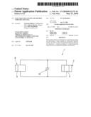
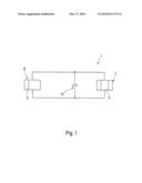
[0014]In the accompanying drawing, a fuel injection system 1 is shown schematically and in highly simplified form. The fuel injection system 1 includes a high-pressure fuel reservoir or a high-pressure fuel source, either of which is also known as a common rail. A plurality of fuel injectors, of which one fuel injector 2 is shown in the accompanying drawing, are connected to the high-pressure fuel reservoir. The fuel injectors serve to inject fuel into the combustion chamber of an internal combustion engine.
[0015]The fuel injector 2 includes a nozzle needle (not shown), which in a targeted way uncovers an injection port in an injector housing, in order to inject fuel. The opening and/or closing motion of the nozzle needle is controlled with the aid of an actuator 4. The actuator 4 is a piezoelectric actuator, which is connected to a voltage source. When current is supplied to the piezoelectric actuator 4, it expands. Analogously, when the piezoelectric actuator is compressed, a voltage is generated in it. A control unit 8 is connected parallel to the actuator 4 and serves to trigger the actuator 4.
[0016]By means of an injection, a high-frequency pressure fluctuation is tripped in the applicable actuator. This causes the piezoelectric actuator 4, which is subjected to high pressure, to be excited, and causes the voltage applied to the piezoelectric actuator 4 to fluctuate. An ensuing injection is affected by the state in which the actuator 4 is located at the onset of the triggering by the control unit 8.
[0017]A voltage-smoothing electrical device 10 is connected parallel to the actuator 4 and to the control unit 8. The voltage-smoothing electrical device 10 is for example an LC sieve member, which includes a coil and a resistor, or an RC sieve member, which includes a resistor and a capacitor.
[0018]In a preferred exemplary embodiment, a capacitor is used as the voltage-smoothing electrical device 10. The parallel-connected capacitor serves to buffer the voltage applied to the actuator 4. As a result, the applied voltage can be smoothed. In the example shown, the amplitude of the bulk wave is reduced.
[0019]In a further aspect of the invention, a switch device 9 is provided, which serves to switch the above-described damping circuit on and off. This has the advantage that the smoothing of the voltage takes place only between two triggering events of the actuator 4. In the exemplary embodiment shown, the switch device 9 is integrated with the control unit 8. The switch device 9 associated with the voltage-smoothing electrical device 10 may, however, also be embodied as a separate component.
Claims:
1-8. (canceled)
9. A fuel injection system, having at least one fuel injector which includes an electrically actuatable actuator and a voltage-smoothing or voltage-damping electrical device connected in parallel to the actuator.
10. The fuel injection system as defined by claim 9, wherein the voltage-smoothing or voltage-damping electrical device includes a capacitor.
11. The fuel injection system as defined by claim 9, wherein the voltage-smoothing or voltage-damping electrical device includes a capacitor, a coil, and/or a resistor.
12. The fuel injection system as defined by claim 9, wherein a switch device is connected in series with the voltage-smoothing or voltage-damping electrical device.
13. The fuel injection system as defined by claim 10, wherein a switch device is connected in series with the voltage-smoothing or voltage-damping electrical device.
14. The fuel injection system as defined by claim 11, wherein a switch device is connected in series with the voltage-smoothing or voltage-damping electrical device.
15. The fuel injection system as defined by claim 9, wherein a control unit is connected parallel to the actuator and to the voltage-smoothing or voltage-damping electrical device.
16. The fuel injection system as defined by claim 10, wherein a control unit is connected parallel to the actuator and to the voltage-smoothing or voltage-damping electrical device.
17. The fuel injection system as defined by claim 11, wherein a control unit is connected parallel to the actuator and to the voltage-smoothing or voltage-damping electrical device.
18. The fuel injection system as defined by claim 12, wherein a control unit is connected parallel to the actuator and to the voltage-smoothing or voltage-damping electrical device.
19. The fuel injection system as defined by claim 13, wherein a control unit is connected parallel to the actuator and to the voltage-smoothing or voltage-damping electrical device.
20. The fuel injection system as defined by claim 14, wherein a control unit is connected parallel to the actuator and to the voltage-smoothing or voltage-damping electrical device.
21. A method for injecting fuel from at least one fuel injector, which includes an electrically actuatable actuator comprising the steps of applying a voltage to the electrically actuatable actuator, and smoothing the voltage which is applied to the actuator.
22. The method as defined by claim 21, wherein via electrical oscillating circuits, a damping circuit is implemented by which amplitudes of bulk waves in a fuel injection system can be reduced markedly, the fuel injection system having at least one fuel injector which includes an electrically actuatable actuator and a voltage-smoothing or voltage-damping electrical device connected in parallel to the actuator.
23. The method as defined by claim 22, wherein the voltage-smoothing or voltage-damping electrical device is switched on in a targeted way between two triggering events of the actuator.
24. The method as defined by claim 22, wherein the voltage-smoothing or voltage-damping electrical device includes a capacitor.
25. The method as defined by claim 22, wherein the voltage-smoothing or voltage-damping electrical device includes a capacitor, a coil, and/or a resistor.
26. The method as defined by claim 22, wherein a switch device is connected in series with the voltage-smoothing or voltage-damping electrical device.
27. The method as defined by claim 22, wherein a control unit is connected parallel to the actuator and to the voltage-smoothing or voltage-damping electrical device.
Description:
[0001]The invention relates to a fuel injection system, having at least
one fuel injector which includes an electrically actuatable actuator. The
invention further relates to a method for injecting fuel from at least
one fuel injector that includes an electrically actuatable actuator to
which a voltage is applied.
PRIOR ART
[0002]The fuel injector serves to inject fuel into a combustion chamber of an internal combustion engine. Preferably, the fuel injection system includes a plurality of fuel injectors, which are triggered via a control unit.
DISCLOSURE OF THE INVENTION
[0003]It is the object of the invention to reduce the hydraulic spacings between two injections.
[0004]The object is attained in a fuel injection system, having at least one fuel injector which includes an electrically actuatable actuator, in that a voltage-smoothing or voltage-damping electrical device is connected parallel to the actuator. In an injection, a pressure wave is introduced into the fuel injection system. As a result, a high-frequency pressure fluctuation is tripped, which excites the actuator subjected to pressure to fluctuate. The actuator is preferably a piezoelectric actuator, which is subjected to pressure and is likewise excited to oscillation by the high-frequency pressure fluctuation, so that a voltage applied to the actuator fluctuates. The ensuing injection is influenced by the state in which the actuator is located at the onset of the triggering. The pressure wave has an influence on the quantity of the ensuing injection and is the tripper of a bulk wave, which is created as a result of pressure fluctuations and acts on the actuator. The bulk wave is the term for the course of the quantity over the chronological spacing of the injections. With the voltage-smoothing or voltage-damping electrical device connected according to the invention, the voltage that is applied to the actuator is smoothed, and thus the bulk wave is likewise smoothed or damped. In one essential aspect of the invention, via electrical oscillating circuits, a damping circuit is implemented by which the amplitudes of bulk waves in the fuel injection system can be reduced markedly.
[0005]A preferred exemplary embodiment of the fuel injection system is characterized in that the voltage-smoothing or voltage-damping electrical device includes a capacitor. The capacitor makes it possible to buffer the voltage that is applied to the actuator. As a result, the amplitude of the bulk wave can be lessened or reduced.
[0006]A further preferred exemplary embodiment of the fuel injection system is characterized in that the voltage-smoothing or voltage-damping electrical device includes a capacitor, a coil, and/or a resistor. Especially preferably, a coil and a resistor, a resistor and a capacitor, or a coil and a resistor are combined in a sieve member.
[0007]A further preferred exemplary embodiment of the fuel injection system is characterized in that a switch device is connected in series with the voltage-smoothing or voltage-damping electrical device. The switch device serves to switch the voltage-smoothing or voltage-damping electrical device on and off in a targeted way. This offers the advantage that the smoothing of the voltage can be performed only between two triggering events. The switch device may be integrated with a control unit.
[0008]A further preferred exemplary embodiment of the fuel injection system is characterized in that a control unit is connected parallel to the actuator and to the voltage-smoothing or voltage-damping electrical device. The control unit serves to trigger the actuator, in order to trip and/or terminate an injection.
[0009]In a method for injecting fuel from at least one fuel injector, which includes an electrically actuatable actuator to which a voltage is applied, the object stated above is attained in that the voltage which is applied to the actuator is smoothed. As a result, a high-frequency pressure fluctuation is tripped that excites the actuator, subjected to pressure, to oscillate, so that the voltage applied to the actuator fluctuates. The ensuing injection is affected by the state in which the actuator is located at the onset of the triggering. Thus the pressure wave affects the quantity of the ensuing injection. According to the invention, the voltage that is applied to the actuator is smoothed, so that the bulk wave is likewise smoothed or damped.
[0010]A preferred exemplary embodiment of the method is characterized in that via electrical oscillating circuits, a damping circuit is implemented by which the amplitudes of bulk waves in a fuel injection system as described above can be reduced markedly. The method of the invention makes it possible to reduce the amplitudes of the bulk waves.
[0011]A further preferred exemplary embodiment of the method is characterized in that the voltage-smoothing or voltage-damping electrical device is switched on in a targeted way between two triggering events of the actuator. This offers the advantage that the smoothing of the voltage is effected only between two triggering events.
[0012]Further advantages, characteristics and details of the invention will become apparent from the ensuing description, in which various exemplary embodiments are described in detail in conjunction with the drawing.
BRIEF DESCRIPTION OF THE DRAWING
[0013]The accompanying drawing shows a schematic, highly simplified view of a fuel injection system according to the invention.
DESCRIPTION OF THE EXEMPLARY EMBODIMENTS
[0014]In the accompanying drawing, a fuel injection system 1 is shown schematically and in highly simplified form. The fuel injection system 1 includes a high-pressure fuel reservoir or a high-pressure fuel source, either of which is also known as a common rail. A plurality of fuel injectors, of which one fuel injector 2 is shown in the accompanying drawing, are connected to the high-pressure fuel reservoir. The fuel injectors serve to inject fuel into the combustion chamber of an internal combustion engine.
[0015]The fuel injector 2 includes a nozzle needle (not shown), which in a targeted way uncovers an injection port in an injector housing, in order to inject fuel. The opening and/or closing motion of the nozzle needle is controlled with the aid of an actuator 4. The actuator 4 is a piezoelectric actuator, which is connected to a voltage source. When current is supplied to the piezoelectric actuator 4, it expands. Analogously, when the piezoelectric actuator is compressed, a voltage is generated in it. A control unit 8 is connected parallel to the actuator 4 and serves to trigger the actuator 4.
[0016]By means of an injection, a high-frequency pressure fluctuation is tripped in the applicable actuator. This causes the piezoelectric actuator 4, which is subjected to high pressure, to be excited, and causes the voltage applied to the piezoelectric actuator 4 to fluctuate. An ensuing injection is affected by the state in which the actuator 4 is located at the onset of the triggering by the control unit 8.
[0017]A voltage-smoothing electrical device 10 is connected parallel to the actuator 4 and to the control unit 8. The voltage-smoothing electrical device 10 is for example an LC sieve member, which includes a coil and a resistor, or an RC sieve member, which includes a resistor and a capacitor.
[0018]In a preferred exemplary embodiment, a capacitor is used as the voltage-smoothing electrical device 10. The parallel-connected capacitor serves to buffer the voltage applied to the actuator 4. As a result, the applied voltage can be smoothed. In the example shown, the amplitude of the bulk wave is reduced.
[0019]In a further aspect of the invention, a switch device 9 is provided, which serves to switch the above-described damping circuit on and off. This has the advantage that the smoothing of the voltage takes place only between two triggering events of the actuator 4. In the exemplary embodiment shown, the switch device 9 is integrated with the control unit 8. The switch device 9 associated with the voltage-smoothing electrical device 10 may, however, also be embodied as a separate component.
User Contributions:
Comment about this patent or add new information about this topic:
| People who visited this patent also read: | |
| Patent application number | Title |
|---|---|
| 20100178289 | THERAPEUTIC USE OF IgG AS A NEUROPROTECTIVE AGENT |
| 20100178288 | USE OF APHANAMIXIS POLYSTACHA EXTRACTS OR FRACTIONS AGAINST 5-LIPOXYGENASE MEDIATED DISEASES |
| 20100178287 | USE OF COAGULATION PROTEINS TO LYSE CLOTS |
| 20100178286 | METHODS AND COMPOSITIONS FOR REDUCING FACIAL LINES AND WRINKLES |
| 20100178285 | SYNERGISTIC ANTHELMINTIC COMPOSITION |
Images included with this patent application:
 |  |
| Similar patent applications: | |
| Date | Title |
|---|---|
| 2012-06-14 | Apparatus and method for controlling fuel injection in a bi-fuel vehicle running on two fuels, i.e. gasoline and lpg |
| 2010-03-18 | Single nozzle injection of gasoline and anti-knock fuel |
| 2010-09-30 | Fuel injection detecting device |
| 2010-09-30 | Fuel injection detecting device |
| 2010-09-30 | Fuel injection detecting device |
| New patent applications in this class: | |
| Date | Title |
|---|---|
| 2018-01-25 | Fuel control systems and methods for delay compensation |
| 2018-01-25 | Method and system for sensor rationality check |
| 2017-08-17 | Intake air temperature estimation system for turbocharged engine |
| 2017-08-17 | Turbocharged engine control device |
| 2016-12-29 | Systems and methods for fuel injection |
| New patent applications from these inventors: | |
| Date | Title |
|---|---|
| 2013-07-04 | Method and device for operating a fuel injection system |
| 2013-01-03 | Starter supply network |
| 2012-08-30 | Method and device for controlling a stop-start program |
| 2012-08-09 | Circuit configuration for a starting device |
| 2012-07-26 | Method for operating a controller for a starter device, controller, and computer program product |
| Top Inventors for class "Data processing: vehicles, navigation, and relative location" | |
| Rank | Inventor's name |
|---|---|
| 1 | Anthony H. Heap |
| 2 | Ajith Kuttannair Kumar |
| 3 | Christopher P. Ricci |
| 4 | Roderick A. Hyde |
| 5 | Lowell L. Wood, Jr. |