Patent application title: SAUNA STOVE HEATING METHOD AND STOVE
Inventors:
Esa Pönkänen (Lieksa, FI)
Esa Pönkänen (Lieksa, FI)
IPC8 Class: AF24C304FI
USPC Class:
431 75
Class name: Combustion timer, programmer, retarder or condition responsive control by combustion or combustion zone sensor
Publication date: 2010-05-06
Patent application number: 20100112499
d to be used for producing heat needed for
bathing, the sauna stove comprising one or more reception elements (2a,
2b) to be heated and a heat source powered by gas energy. The heat source
of the stove is arranged to produce infrared heat radiation, whereby one
or more reception elements (2a, 2b) are arranged close to the heat source
to heat the reception elements with the infrared heat radiation produced
by gas energy.Claims:
1-10. (canceled)
11. A sauna stove to be used for producing heat needed for bathing, the sauna stove comprising one or more reception elements to be heated and a heat source powered by gas energy, wherein in that the heat source is a gas energy infrared radiator arranged to produce infrared heat radiation, whereby one or more reception elements are arranged close to the radiator to heat the reception elements with the infrared heat radiation produced with the radiator from the gas energy.
12. A sauna stove as claimed in claim 11, wherein the reception element comprises at least one radiator arranged substantially at a gas energy infrared heat radiation distance from the reception element.
13. A sauna stove as claimed in claim 11 provided with a frame, wherein the frame part comprises at least one radiator arranged substantially at a gas energy infrared heat radiation distance from the reception element.
14. A sauna stove as claimed in claim 13, wherein the frame part and/or the reception element comprises one or more openings, and a channel for leading convection flows is arranged in this opening.
15. A sauna stove as claimed in claim 14, wherein a closing flap is arranged in the channel of the frame part.
16. A sauna stove as claimed in claim 13, wherein the frame part is at a sauna furnace provided with an opening, at which a lid is arranged.
17. A sauna stove as claimed in claim 16, wherein on the side of the sauna furnace the edges of the opening are arranged to extend substantially lower than the upper edge of the radiator.
18. A sauna stove as claimed in claim 12, wherein the upper surface of the frame part and/or of the reception element is arranged to be inclined.
19. A sauna stove as claimed in claim 11, wherein the outer surface of the frame part or of the reception element is provided with an operating means for gas flow and an operating means for a spark igniter, and inside thereof there are an oxygen sensor and a flame detector.
20. A method for heating a sauna stove, the stove comprising one or more reception elements, wherein the method comprising the steps ofproducing infrared heat radiation from gas energy with a gas energy infrared radiator, andheating one or more reception elements with the infrared heat radiation produced with the radiator from the gas energy to heat the sauna stove.
21. A sauna stove as claimed in claim 13, wherein the upper surface of the frame part and/or of the reception element is arranged to be inclined.
22. A sauna stove as claimed in claim 14, wherein the upper surface of the frame part and/or of the reception element is arranged to be inclined.Description:
[0001]The invention relates to a method for heating a sauna stove as
claimed in the preamble of claim 1, and a sauna stove according to the
method.
[0002]Known methods for heating a sauna stove are based on the use of wood or electricity as a heat source and transmission of heat produced by this method by conducting it through contact surfaces to sauna stones. The efficiency of heat transmission based on conduction is poor, wherefore it takes a long time, usually about an hour, to heat the sauna stove. In addition, stoves that are based on the above-mentioned method have a heavy structure and are thus unsuitable for camping or travelling purposes, for example.
[0003]Many sauna enthusiasts have, however, provided their boat or caravan with sauna facilities. In these cases the stoves are, almost without exception, heated with wood, which means that wood needed for heating must be carried along, which takes space and is laborious.
[0004]From an ecological point of view, a wood stove produces a high amount of fine particles and hydrocarbon emissions, whereas the use of electricity is problematic because of great losses in production and transmission.
[0005]Sauna stoves have been built for dozens of years based on this philosophy, and no significant progress has happened in the field, except for the inventions described in patents FI108213B and FI115114B, for instance.
[0006]In some cases it is necessary that the sauna stove is transportable. A typical source of energy used by caravanners and sailors in cookers and grills is bottled gas, i.e. propane. A gas-fired stove heating method would thus be the most natural solution in these purposes, but a working solution has not been found for heating a gas stove. The biggest problem has been a typical characteristic of gas when it is burnt with a free flame. A gas flame lacks almost entirely the free carbon particles, the glowing of which would produce flame radiation essential for forming infrared heat radiation. The most common method of utilizing the heat energy of gas combustion is thus based on convection, i.e. heat transmission, as a hot low-density substance rises upwards in the gravitational field.
[0007]Due to the above facts, the development of a heating method for gas stoves cannot be based on known heating methods for wood or electric stoves.
[0008]A chance of utilizing a gas stove has long existed in camping as well as in regions where natural gas is generally available. In addition, emission standards, which become stricter in the future, will probably limit the use of traditional wood stoves particularly in densely populated countries. Gas would thus provide a good foundation for using a clean heating method, especially as the combustion products of gas are heat, water and carbon dioxide.
[0009]The above disadvantages can be eliminated and the aforementioned objects are achieved by a method of the invention for heating a sauna stove and a sauna stove according to the method, characterized by what is defined in the characterizing part of the claims.
[0010]One of the most significant qualities of the invention is the high efficiency of the sauna stove. In few minutes the stove is heated and is ready for use, which significantly reduces the energy consumption. This is based, first of all, on infrared heat radiation produced in the stove by gas energy and its large area as well as on the quickly achieved temperature of 1000 degrees. Secondly, it is based on the large area of reception elements (vaporizer surface/sauna stones) and their good capability of infrared heat radiation absorption and, thirdly, on unrestricted infrared heat radiation as well as the distance between the infrared radiant heater and the reception elements.
[0011]The sauna stove according to the invention may be manufactured cost-efficiently from known components and raw materials that have been in use for a long time and, if required, it can be made lighter than the traditional stoves. It is thus clear that due to the above facts, economic benefit is achieved and that there is an obvious demand for such a stove.
[0012]A substantial advantage of the invention is also the ecological significance of the stove, when compared with other corresponding methods. The ecological efficiency of natural gas is 65 to 70%, whereas that of electricity is 45 to 50% and that of oil 55 to 60%.
[0013]It can also be mentioned that the new method for heating a sauna stove and the sauna stove of the method opens up entirely new markets for a new type of sauna solutions, the key factors of which are transportability, easy manageability and quick heating. The invention creates new businesses and does not compete with already existing market players.
[0014]In the following, the invention will be described in greater detail with reference to the attached figures, in which
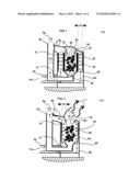
[0015]FIG. 1 schematically shows an embodiment of the invention cut from the middle at the stage of heating a sauna stove,
[0016]FIG. 2 schematically shows an embodiment of the invention cut from the middle at the stage of using the sauna stove for bathing,
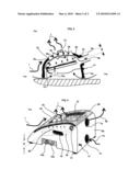
[0017]FIG. 3 schematically shows an embodiment of the invention cut from the middle at the heating and bathing stages of the sauna stove,
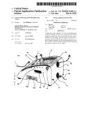
[0018]FIG. 4 shows an embodiment of the invention obliquely from behind.
[0019]The figures show the following parts of a sauna stove: a reception element 2a, 2b as well a radiator 3a and a gas energy infrared heat radiation distance 3c between them. A frame 6a provided with an operating means 10a, 10b, lifting means 16 and openings 7a, 7c, which, for their part, are provided with channels 5a, 5b and a closing flap 8. A sauna furnace 4a, at which there is an opening 7b with its edges 18, and a lid 4c arranged thereon as well as a cavity 12 and an inclined upper surface 6b. Inside the frame 6a there are also an oxygen sensor 14 and a flame detector 15.
[0020]In the sauna stove of the invention, one or more reception elements 2a, 2b are heated by means of gas energy infrared heat radiation 3b. The reception element 2a comprises at least one radiator 3a arranged essentially at a gas energy infrared heat radiation distance 3c from the reception element 2a, 2b.
[0021]Gas energy infrared heat radiation 3b is prior art, and is used most commonly in small local heaters and, for instance, in various processes of the paper industry because of its efficiency, easy controllability and non-polluting properties. The burners of known gas energy infrared radiant heaters are most commonly based on utilization of a 3D ceramic tile mesh or catalytic wool in flameless gas combustion. This prior art is also used in the present invention to produce gas energy infrared radiation 3b for the stove and to heat the reception elements 2a, 2b.
[0022]FIG. 1 shows a structure solution of the invention schematically, in which the radiator 3a converts the energy contained in the gas into gas energy infrared heat radiation 3b. The radiator 3a is arranged to radiate unrestrictedly at a gas energy infrared heat radiation distance 3c from the reception element 2a in order to heat it up as efficiently as possible. The thickness of the reception element 2a affects the heating properties of the sauna stove and its purpose of use. The figures show a convection flow 9b caused by gas combustion and arranged in such a manner that the upper surface 6b of the frame part 6a is arranged to be inclined, the frame part 6a comprising one or more openings 7a, 7c, which are provided with a channel 5a, 5b with a closing flap 8 for closing the channel 5a, 5b. The convection flow 9b may thus be utilized, firstly, for heating the reception elements 2b by leading the convection flow 9b through the lower part 4b of the sauna furnace 4a into the channel 5a and from there to outside air 11b and, secondly, for bringing in the outside air 11b through the channel 5b.
[0023]FIG. 2 shows a structure solution of the invention schematically, in which the radiator 3a heats the reception elements 2b directly. In this solution, the hot radiating surfaces of the radiator 3a must be protected with some method in order to prevent harmful effects of splashes of sauna water. For instance, glass surfaces that tolerate heat variations may be used for this protection. The frame part 6a is at the sauna furnace 4a provided with an opening 7b, to which sauna water is thrown. To speed up the heating, the opening 7b is provided with a lid 4c. On the side of the sauna furnace 4a the edges 18 of the opening 7b are arranged to extend substantially lower than the upper edge of the radiator 3a, and so exhaust gases 9a are not discharged from the opening 7b into a sauna room 11a when the lid 4c is open.
[0024]FIG. 3 shows a structure solution of the invention schematically, in which the reception element 2a comprises at least one radiator 3a arranged to radiate unrestrictedly substantially at a gas energy infrared heat radiation distance 3c from the reception element 2a in order to heat it up as efficiently as possible.
[0025]In the figure the convection flow 9b is arranged in such a manner that the upper surface 6b of the reception element 2a is inclined and the reception element 2a comprises one or more openings 7a provided with a channel 5a, through which exhaust gases 9a flow into the outside air 11b. The radiator 3a takes the air required for gas burning from the sauna room 11a from below the lower edge of the reception element 2a. This sauna stove model could be used most preferably in saunas where it is easy to arrange sufficient ventilation, such as in tent saunas.
[0026]At the reception element 2a there is arranged a cavity 12 with reception elements 2b, and a bowl 13 with a lid for an odorizer, such as alder chips. A warm steam flow 1 is shown in the figure by an arrow. A flame detector 15 is arranged inside the reception element 2a.
[0027]FIG. 4 shows a structure solution of the sauna stove of the invention, in which the frame part 6a comprises at least one radiator 3a arranged to radiate unrestrictedly substantially at a gas energy infrared heat radiation distance 3c from the reception element 2a in such a manner that it would heat up as efficiently as possible.
[0028]The outer surface of the frame part 6a is provided with an operating means 10a for gas flow and an operating means 10b for a spark igniter, which are used for switching the stove on and off and controlling the power of the stove. The outer surface of the frame 6a is provided with lifting means 16, and inside the frame 6a there is an oxygen sensor 14, which turns off the gas supply if the oxygen level of the sauna room 11a decreases too much.
[0029]The frame part 6a, the lid 4c, the channels 5a, 5b and the flap 8 are most preferably made of stainless steel or other metal and formed as solutions having a shape of a plate, a cylinder or a casing. The reception element 2a is most preferably made of a heat-resistant stone-based or ceramic raw material, such as soapstone or a heat-resistant castable, and shaped as planar or like a cylinder, a casing or a bowl. Other shapes are also possible. The reception elements 2b are most preferably previously known, typical sauna stones.
[0030]All parts of the sauna stove of the invention may be made of known raw materials and with known manufacturing methods and machines. Other generally known fuels that are in liquid form at standard atmospheric pressure, such as paraffin oil, may also be used, whereby gassing occurs with known techniques by utilizing heat and pressure.
[0031]The method of the present invention mainly describes the sauna stove according to the method by means of a few structural alternatives only. It is obvious to a person skilled in the art that the invention is not restricted to the above alternatives only, but many variations are feasible within the inventive idea defined by the appended claims.
Claims:
1-10. (canceled)
11. A sauna stove to be used for producing heat needed for bathing, the sauna stove comprising one or more reception elements to be heated and a heat source powered by gas energy, wherein in that the heat source is a gas energy infrared radiator arranged to produce infrared heat radiation, whereby one or more reception elements are arranged close to the radiator to heat the reception elements with the infrared heat radiation produced with the radiator from the gas energy.
12. A sauna stove as claimed in claim 11, wherein the reception element comprises at least one radiator arranged substantially at a gas energy infrared heat radiation distance from the reception element.
13. A sauna stove as claimed in claim 11 provided with a frame, wherein the frame part comprises at least one radiator arranged substantially at a gas energy infrared heat radiation distance from the reception element.
14. A sauna stove as claimed in claim 13, wherein the frame part and/or the reception element comprises one or more openings, and a channel for leading convection flows is arranged in this opening.
15. A sauna stove as claimed in claim 14, wherein a closing flap is arranged in the channel of the frame part.
16. A sauna stove as claimed in claim 13, wherein the frame part is at a sauna furnace provided with an opening, at which a lid is arranged.
17. A sauna stove as claimed in claim 16, wherein on the side of the sauna furnace the edges of the opening are arranged to extend substantially lower than the upper edge of the radiator.
18. A sauna stove as claimed in claim 12, wherein the upper surface of the frame part and/or of the reception element is arranged to be inclined.
19. A sauna stove as claimed in claim 11, wherein the outer surface of the frame part or of the reception element is provided with an operating means for gas flow and an operating means for a spark igniter, and inside thereof there are an oxygen sensor and a flame detector.
20. A method for heating a sauna stove, the stove comprising one or more reception elements, wherein the method comprising the steps ofproducing infrared heat radiation from gas energy with a gas energy infrared radiator, andheating one or more reception elements with the infrared heat radiation produced with the radiator from the gas energy to heat the sauna stove.
21. A sauna stove as claimed in claim 13, wherein the upper surface of the frame part and/or of the reception element is arranged to be inclined.
22. A sauna stove as claimed in claim 14, wherein the upper surface of the frame part and/or of the reception element is arranged to be inclined.
Description:
[0001]The invention relates to a method for heating a sauna stove as
claimed in the preamble of claim 1, and a sauna stove according to the
method.
[0002]Known methods for heating a sauna stove are based on the use of wood or electricity as a heat source and transmission of heat produced by this method by conducting it through contact surfaces to sauna stones. The efficiency of heat transmission based on conduction is poor, wherefore it takes a long time, usually about an hour, to heat the sauna stove. In addition, stoves that are based on the above-mentioned method have a heavy structure and are thus unsuitable for camping or travelling purposes, for example.
[0003]Many sauna enthusiasts have, however, provided their boat or caravan with sauna facilities. In these cases the stoves are, almost without exception, heated with wood, which means that wood needed for heating must be carried along, which takes space and is laborious.
[0004]From an ecological point of view, a wood stove produces a high amount of fine particles and hydrocarbon emissions, whereas the use of electricity is problematic because of great losses in production and transmission.
[0005]Sauna stoves have been built for dozens of years based on this philosophy, and no significant progress has happened in the field, except for the inventions described in patents FI108213B and FI115114B, for instance.
[0006]In some cases it is necessary that the sauna stove is transportable. A typical source of energy used by caravanners and sailors in cookers and grills is bottled gas, i.e. propane. A gas-fired stove heating method would thus be the most natural solution in these purposes, but a working solution has not been found for heating a gas stove. The biggest problem has been a typical characteristic of gas when it is burnt with a free flame. A gas flame lacks almost entirely the free carbon particles, the glowing of which would produce flame radiation essential for forming infrared heat radiation. The most common method of utilizing the heat energy of gas combustion is thus based on convection, i.e. heat transmission, as a hot low-density substance rises upwards in the gravitational field.
[0007]Due to the above facts, the development of a heating method for gas stoves cannot be based on known heating methods for wood or electric stoves.
[0008]A chance of utilizing a gas stove has long existed in camping as well as in regions where natural gas is generally available. In addition, emission standards, which become stricter in the future, will probably limit the use of traditional wood stoves particularly in densely populated countries. Gas would thus provide a good foundation for using a clean heating method, especially as the combustion products of gas are heat, water and carbon dioxide.
[0009]The above disadvantages can be eliminated and the aforementioned objects are achieved by a method of the invention for heating a sauna stove and a sauna stove according to the method, characterized by what is defined in the characterizing part of the claims.
[0010]One of the most significant qualities of the invention is the high efficiency of the sauna stove. In few minutes the stove is heated and is ready for use, which significantly reduces the energy consumption. This is based, first of all, on infrared heat radiation produced in the stove by gas energy and its large area as well as on the quickly achieved temperature of 1000 degrees. Secondly, it is based on the large area of reception elements (vaporizer surface/sauna stones) and their good capability of infrared heat radiation absorption and, thirdly, on unrestricted infrared heat radiation as well as the distance between the infrared radiant heater and the reception elements.
[0011]The sauna stove according to the invention may be manufactured cost-efficiently from known components and raw materials that have been in use for a long time and, if required, it can be made lighter than the traditional stoves. It is thus clear that due to the above facts, economic benefit is achieved and that there is an obvious demand for such a stove.
[0012]A substantial advantage of the invention is also the ecological significance of the stove, when compared with other corresponding methods. The ecological efficiency of natural gas is 65 to 70%, whereas that of electricity is 45 to 50% and that of oil 55 to 60%.
[0013]It can also be mentioned that the new method for heating a sauna stove and the sauna stove of the method opens up entirely new markets for a new type of sauna solutions, the key factors of which are transportability, easy manageability and quick heating. The invention creates new businesses and does not compete with already existing market players.
[0014]In the following, the invention will be described in greater detail with reference to the attached figures, in which
[0015]FIG. 1 schematically shows an embodiment of the invention cut from the middle at the stage of heating a sauna stove,
[0016]FIG. 2 schematically shows an embodiment of the invention cut from the middle at the stage of using the sauna stove for bathing,
[0017]FIG. 3 schematically shows an embodiment of the invention cut from the middle at the heating and bathing stages of the sauna stove,
[0018]FIG. 4 shows an embodiment of the invention obliquely from behind.
[0019]The figures show the following parts of a sauna stove: a reception element 2a, 2b as well a radiator 3a and a gas energy infrared heat radiation distance 3c between them. A frame 6a provided with an operating means 10a, 10b, lifting means 16 and openings 7a, 7c, which, for their part, are provided with channels 5a, 5b and a closing flap 8. A sauna furnace 4a, at which there is an opening 7b with its edges 18, and a lid 4c arranged thereon as well as a cavity 12 and an inclined upper surface 6b. Inside the frame 6a there are also an oxygen sensor 14 and a flame detector 15.
[0020]In the sauna stove of the invention, one or more reception elements 2a, 2b are heated by means of gas energy infrared heat radiation 3b. The reception element 2a comprises at least one radiator 3a arranged essentially at a gas energy infrared heat radiation distance 3c from the reception element 2a, 2b.
[0021]Gas energy infrared heat radiation 3b is prior art, and is used most commonly in small local heaters and, for instance, in various processes of the paper industry because of its efficiency, easy controllability and non-polluting properties. The burners of known gas energy infrared radiant heaters are most commonly based on utilization of a 3D ceramic tile mesh or catalytic wool in flameless gas combustion. This prior art is also used in the present invention to produce gas energy infrared radiation 3b for the stove and to heat the reception elements 2a, 2b.
[0022]FIG. 1 shows a structure solution of the invention schematically, in which the radiator 3a converts the energy contained in the gas into gas energy infrared heat radiation 3b. The radiator 3a is arranged to radiate unrestrictedly at a gas energy infrared heat radiation distance 3c from the reception element 2a in order to heat it up as efficiently as possible. The thickness of the reception element 2a affects the heating properties of the sauna stove and its purpose of use. The figures show a convection flow 9b caused by gas combustion and arranged in such a manner that the upper surface 6b of the frame part 6a is arranged to be inclined, the frame part 6a comprising one or more openings 7a, 7c, which are provided with a channel 5a, 5b with a closing flap 8 for closing the channel 5a, 5b. The convection flow 9b may thus be utilized, firstly, for heating the reception elements 2b by leading the convection flow 9b through the lower part 4b of the sauna furnace 4a into the channel 5a and from there to outside air 11b and, secondly, for bringing in the outside air 11b through the channel 5b.
[0023]FIG. 2 shows a structure solution of the invention schematically, in which the radiator 3a heats the reception elements 2b directly. In this solution, the hot radiating surfaces of the radiator 3a must be protected with some method in order to prevent harmful effects of splashes of sauna water. For instance, glass surfaces that tolerate heat variations may be used for this protection. The frame part 6a is at the sauna furnace 4a provided with an opening 7b, to which sauna water is thrown. To speed up the heating, the opening 7b is provided with a lid 4c. On the side of the sauna furnace 4a the edges 18 of the opening 7b are arranged to extend substantially lower than the upper edge of the radiator 3a, and so exhaust gases 9a are not discharged from the opening 7b into a sauna room 11a when the lid 4c is open.
[0024]FIG. 3 shows a structure solution of the invention schematically, in which the reception element 2a comprises at least one radiator 3a arranged to radiate unrestrictedly substantially at a gas energy infrared heat radiation distance 3c from the reception element 2a in order to heat it up as efficiently as possible.
[0025]In the figure the convection flow 9b is arranged in such a manner that the upper surface 6b of the reception element 2a is inclined and the reception element 2a comprises one or more openings 7a provided with a channel 5a, through which exhaust gases 9a flow into the outside air 11b. The radiator 3a takes the air required for gas burning from the sauna room 11a from below the lower edge of the reception element 2a. This sauna stove model could be used most preferably in saunas where it is easy to arrange sufficient ventilation, such as in tent saunas.
[0026]At the reception element 2a there is arranged a cavity 12 with reception elements 2b, and a bowl 13 with a lid for an odorizer, such as alder chips. A warm steam flow 1 is shown in the figure by an arrow. A flame detector 15 is arranged inside the reception element 2a.
[0027]FIG. 4 shows a structure solution of the sauna stove of the invention, in which the frame part 6a comprises at least one radiator 3a arranged to radiate unrestrictedly substantially at a gas energy infrared heat radiation distance 3c from the reception element 2a in such a manner that it would heat up as efficiently as possible.
[0028]The outer surface of the frame part 6a is provided with an operating means 10a for gas flow and an operating means 10b for a spark igniter, which are used for switching the stove on and off and controlling the power of the stove. The outer surface of the frame 6a is provided with lifting means 16, and inside the frame 6a there is an oxygen sensor 14, which turns off the gas supply if the oxygen level of the sauna room 11a decreases too much.
[0029]The frame part 6a, the lid 4c, the channels 5a, 5b and the flap 8 are most preferably made of stainless steel or other metal and formed as solutions having a shape of a plate, a cylinder or a casing. The reception element 2a is most preferably made of a heat-resistant stone-based or ceramic raw material, such as soapstone or a heat-resistant castable, and shaped as planar or like a cylinder, a casing or a bowl. Other shapes are also possible. The reception elements 2b are most preferably previously known, typical sauna stones.
[0030]All parts of the sauna stove of the invention may be made of known raw materials and with known manufacturing methods and machines. Other generally known fuels that are in liquid form at standard atmospheric pressure, such as paraffin oil, may also be used, whereby gassing occurs with known techniques by utilizing heat and pressure.
[0031]The method of the present invention mainly describes the sauna stove according to the method by means of a few structural alternatives only. It is obvious to a person skilled in the art that the invention is not restricted to the above alternatives only, but many variations are feasible within the inventive idea defined by the appended claims.
User Contributions:
Comment about this patent or add new information about this topic:
Images included with this patent application:
 |  |
 |
| Similar patent applications: | |
| Date | Title |
|---|---|
| 2009-05-14 | Swirling-type furnace operating method and a swirling-type furnace |
| 2010-11-18 | Burner system having premixed burners and flame transfer means |
| 2011-01-27 | Novel reactor for carrying out very high temperature and high pressure reactions |
| 2011-02-03 | Candle having a planar wick and method of and equipment for making same |
| 2011-02-03 | Candle having a planar wick and method of and equipment for making same |
| New patent applications in this class: | |
| Date | Title |
|---|---|
| 2018-01-25 | Prefabricated integrated combustion assemblies and methods of installing the same into a combustion system |
| 2015-01-15 | Systems and methods for advanced closed loop control and improvement of combustion system operation |
| 2013-10-17 | Dual fuel heater |
| 2012-11-01 | Burner system |
| 2011-01-20 | Coal-fired power station and method for operating the coal-fired power station |
| Top Inventors for class "Combustion" | |
| Rank | Inventor's name |
|---|---|
| 1 | Christopher A. Wiklof |
| 2 | Igor A. Krichtafovitch |
| 3 | Joseph Colannino |
| 4 | David Deng |
| 5 | Robert E. Breidenthal |