Patent application title: BUILDING ENTRANCE TERMINAL BOX WITH MODULAR PANELS
Inventors:
Mark Steven Curtis (Gretna, NE, US)
IPC8 Class: AH05K502FI
USPC Class:
174 51
Class name: Electricity: conductors and insulators boxes and housings with grounding means
Publication date: 2010-05-06
Patent application number: 20100108346
nal box using modular panels. The connection
chamber of the box receives modular panels which snap into place without
the need for screws. Each module includes a prewired surge protection
field and output wire termination device. The surge protection field is
also prewired to a connector for mating with the input wire termination
device in the splice chamber. When the module is snapped into place, a
connection is made with a grounding bar automatically. Various size
modules may be used within a box.Claims:
1. A building entrance terminal box comprising:a splice chamber;a
connection chamber;a wall separating the splice chamber from the
connection chamber;an input wire termination device in the splice
chamber; andat least one module mounted in said connection chamber, said
module having a surge protection field and an output wire termination
device which are prewired on the module, said module also including a
connector prewired to said surge protection field for mating with said
input wire termination device.
2. The building entrance terminal box of claim 1, further comprising a ground bar in said connection chamber which connects to a ground connector associated with each module so that said ground connector snaps onto said ground bar when said module is installed.
3. The building entrance terminal box of claim 2, wherein said ground connector is Y-shaped.
4. The building entrance terminal box of claim 2, wherein said ground connector is mounted on a bottom of said module.
5. The building entrance terminal box of claim 2, wherein the ground bar is L-shaped in cross section with a first section being continuous and mounted on a back surface of said box and a second section being segmented and extending away from the back surface of the box for connection with the modules.
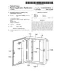
6. The building entrance terminal box of claim 5, wherein sidewalls of the modules extend into openings between segments of the second section of the ground bar.
7. The building entrance terminal box of claim 1, wherein each module has a tab arrangement along one bottom edge for being received in openings in said connection chamber in order to locate each module.
8. The building entrance terminal box of claim 1, wherein said wall includes at least one slot for receiving wires connecting said connector to said surge protection field so that said connector is received in the splice chamber while the module is placed in the connection chamber.
9. A module for use in a building entrance terminal box, said module comprising:a top surface and sidewalls depending therefrom;a surge protection field mounted on said top surface;an output termination device mounted on said top surface;said surge protection field and said output termination device being prewired along a bottom of said top surface; andan input connector prewired to said surge protection field;whereby said module may be mounted in a building entrance terminal box with the input connector mounted to an input termination device.
10. The module according to claim 9, further comprising a Y-shaped ground connector mounted on the bottom of said top surface for interconnection with a ground bar in said building entrance terminal box.
11. The module according to claim 9, wherein said surge protection field receives a plurality of surge protection modules
12. The module according to claim 9, further comprising a flange and tab arrangement along a bottom edge of one sidewall for mating with openings in said building entrance terminal box for holding the module in position within the box.
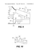
13. A building entrance terminal box, comprising:a splice chamber;a connection chamber;a wall separating the splice chamber from the connection chamber;a plurality of modules mounted in said connection chamber, each of said modules having a surge protection field and an output wire termination device prewired on the module;each module having a tab arrangement along an edge for connecting said module to said connection chamber;said connection chamber including a plurality of slot arrangements, with each slot arrangement receiving a tab arrangement of one module so as to locate the corresponding module in the connection chamber.
14. The building entrance terminal box of claim 13, wherein said module snaps into position when said tab arrangement is placed in said slot arrangement.
15. The building entrance terminal box of claim 14, further comprising a ground bar in said connection chamber.
16. The building entrance terminal box of claim 15, wherein each module includes a ground connection mounted on a bottom of said module.
17. The building entrance terminal box of claim 16, wherein the ground connector is Y-shaped and snaps onto said ground bar when said module is installed in said connection chamber.
18. The building entrance terminal box of claim 15, wherein the ground bar is L-shaped in cross section with a first section being continuous and mounted on a back surface of said box and a second section being segmented and extending away from the back surface of the box for connection with the modules.
19. The building entrance terminal box of claim 18, wherein sidewalls of the modules extend into openings between segments of the second section of the ground bar.
20. The building entrance terminal box of claim 13, wherein each module includes a connector prewired to said surge protection field for mating with an input wire termination device located in said splice chamber.Description:
BACKGROUND OF THE INVENTION
[0001]The present invention relates to a building entrance terminal box for telecommunication lines and more particularly a building entrance protector box where the panels are modular and may be snapped into place to achieve an automatic ground.
DESCRIPTION OF THE BACKGROUND
[0002]When telephone or other communication lines enter a building such as an office building or apartment building, it is common to use a building entrance terminal box in order to connect the incoming lines with the individual lines that are used within the building. Such a prior art box 10 is shown in FIG. 1 as having two separate chambers, a splice chamber 14 and a connection chamber 16. A wall 30 divides the two chambers. The main cable from outside 12 enters the box in the splice chamber and is wired to an input wire termination device 18. The termination device is made of an array of terminal connectors 28. The individual wires from the main cable 12 are connected to a corresponding connector 28. These connectors are then connected by a bundle of wires which extend through the wall 30 into the connection chamber. The connection chamber includes a surge protector panel 22 and an output wire termination device 24. Each of the wires from the input wire termination device 18 is connected to a corresponding surge protector port 20 in the surge protector panel 22. Each port consists of a pattern of holes for receiving conductor pins of a surge protector module 25. Typically, the surge protector module is a box shaped device having a pattern of five pins which mate with the holes of the individual ports 20. These modules are designed to protect the lines from surges in the incoming telephone lines. Each protector port is then connected to one of the connectors of the output wire termination device 24. From this termination device, individual lines exit the box and are directed to various parts of the building.
[0003]FIG. 2 shows a cross-sectional view of this same device. As seen in this view, the terminal connectors 28 receive input wires 12 on a top surface and wires are wire wrapped to terminal leads 26 on a bottom surface of the connector. The wires are lead through a hole 32 in wall 30 and are wire wrapped to terminals 34 on the bottom surface of the surge protector panel 22. Outgoing wires are also wire wrapped to other terminals of the panel 22 and extend to terminals of the output termination device 24. As is also seen, the output termination device 24 and surge protector panel 22 are mounted on a panel 23 so as to divide the chamber 16 into an outer part and an inner part, with the inner part receiving the various wires. By utilizing an arrangement such as this, the splice chamber 14 is separated from the connection chamber 16. This prevents the incoming wires from possibly being short circuited to the output wires. It also allows the splice chamber to be enclosed for fire protection in the case of sparks resulting from a surge.
[0004]U.S. Pat. Nos. 6,191,357 and 5,942,725 show building entrance protector boxes having modular protector panels which are self grounding. While various modules are used in this arrangement, these are only modules for the surge protector panel and not modules for the entire connection chamber.
[0005]While the prior art devices shown in FIGS. 1 and 2 are workable, the building entrance terminal box is wired as a discrete unit that is costly and difficult to reconfigure. Thus, it does not lend itself to being used in boxes of other configurations. It does not allow a modular approach so that a series of splice chambers and ground systems of a few sizes can be kept in inventory and assembled together in a number of different configurations. When an order for a particular box is received, it is desirable that pre-wired modules may be snapped together in an enclosure of a desired size. Further, the factory or customer may remove a module and replace it at any time with little effort to form a different configuration.
SUMMARY OF THE INVENTION
[0006]The present invention is a building entrance terminal box which utilizes modular panels to simplify construction of the box in the factory and the field installation of the box. The individual panels within the connection chamber include both protector panel sections and output termination devices which are prewired. The input connector is also pre-wired to the modular panel. The modules merely snap in place and are designed to make an easy connection with the input termination device. As a result, installation time is reduced and simplified with fewer mistakes. The individual modules are also automatically grounded upon their snapping into position.
[0007]Accordingly, the present invention provides a building entrance terminal box with modular panels.
[0008]The present invention further provides a building entrance terminal box which is simple to install by using modular devices.
[0009]The present invention also provides a building entrance terminal box with an automatic grounding for modules.
[0010]The present invention still further provides a building entrance terminal box with modules that easily snap into place for fast installation.
[0011]The present invention further provides a building entrance terminal box which is simple in design and inexpensive to make and install, and to expand or retrofit by the customer in the field.
BRIEF DESCRIPTION OF THE DRAWINGS
[0012]A more complete appreciation of the invention and many of the attendant advantages will be readily appreciated as the same becomes better understood by reference to the following detailed description when considered in connection with the accompanying drawings, wherein:
[0013]FIG. 1 is a front view of a prior art device;
[0014]FIG. 2 is a cross sectional view of the prior art device of FIG. 1;
[0015]FIG. 3 is a perspective view of one example of a building entrance terminal box of the present invention;
[0016]FIG. 4 is a perspective view of a building entrance terminal box of the present invention having modular panels installed;
[0017]FIG. 5 is a cutaway view of the present invention showing the installation of modules;
[0018]FIG. 6 is a perspective view of a modular panel of a second type used in the present invention;
[0019]FIG. 7 is a perspective view of a modular panel of a third type used in the present invention;
[0020]FIG. 8 is a perspective view of a modular panel of a fourth type used in the present invention;
[0021]FIG. 9 is a cross sectional view of a module of the present invention being installed; and
[0022]FIG. 10 is a perspective view of the grounding bar used in the present invention;
DESCRIPTION OF THE PREFERRED EMBODIMENTS
[0023]The present invention now is described more fully hereinafter with reference to the accompanying drawings, in which embodiments of the invention are shown. This invention may, however, be embodied in many different forms and should not be construed as limited to the embodiments set forth herein; rather, these embodiments are provided so that this disclosure will be thorough and complete, and will fully convey the scope of the invention to those skilled in the art.
[0024]Like numbers refer to like elements throughout. In the figures, the thickness of certain lines, layers, components, elements or features may be exaggerated for clarity. Broken lines illustrate optional features or operations unless specified otherwise.
[0025]The terminology used herein is for the purpose of describing particular embodiments only and is not intended to be limiting of the invention. Unless otherwise defined, all terms (including technical and scientific terms) used herein have the same meaning as commonly understood by one of ordinary skill in the art to which this invention belongs. It will be further understood that terms, such as those defined in commonly used dictionaries, should be interpreted as having a meaning that is consistent with their meaning in the context of the specification and relevant art and should not be interpreted in an idealized or overly formal sense unless expressly so defined herein. Well-known functions or constructions may not be described in detail for brevity and/or clarity.
[0026]As used herein, the singular forms "a", "an" and "the" are intended to include the plural forms as well, unless the context clearly indicates otherwise. It will be further understood that the terms "comprises" and/or "comprising," when used in this specification, specify the presence of stated features, integers, steps, operations, elements, and/or components, but do not preclude the presence or addition of one or more other features, integers, steps, operations, elements, components, and/or groups thereof. As used herein, the term "and/or" includes any and all combinations of one or more of the associated listed items. As used herein, phrases such as "between X and Y" and "between about X and Y" should be interpreted to include X and Y. As used herein, phrases such as "between about X and Y" mean "between about X and about Y." As used herein, phrases such as "from about X to Y" mean "from about X to about Y."
[0027]It will be understood that when an element is referred to as being "on", "attached" to, "connected" to, "coupled" with, "contacting", etc., another element, it can be directly on, attached to, connected to, coupled with or contacting the other element or intervening elements may also be present. In contrast, when an element is referred to as being, for example, "directly on", "directly attached" to, "directly connected" to, "directly coupled" with or "directly contacting" another element, there are no intervening elements present. It will also be appreciated by those of skill in the art that references to a structure or feature that is disposed "adjacent" another feature may have portions that overlap or underlie the adjacent feature.
[0028]Spatially relative terms, such as "under", "below", "lower", "over", "upper", "lateral", "left", "right" and the like, may be used herein for ease of description to describe one element or feature's relationship to another element(s) or feature(s) as illustrated in the figures. It will be understood that the spatially relative terms are intended to encompass different orientations of the device in use or operation in addition to the orientation depicted in the figures. For example, if the device in the figures is inverted, elements described as "under" or "beneath" other elements or features would then be oriented "over" the other elements or features. The device may be otherwise oriented (rotated 90 degrees or at other orientations) and the descriptors of relative spatial relationships used herein interpreted accordingly.
[0029]The entrance terminal box of the present invention is shown as 100 in FIG. 3. The box includes a splice chamber 114 and connection chamber 116, in a similar fashion to the prior art. A wall 130 divides the two chambers. However, keyholes 132 are provided for receiving wire connections between the input termination device and the modular panels. An outer door 142 is provided to enclose the box for security and safety purposes. A latching arrangement 144, which may include a lock is provided on the door and the frame in order to hold the door securely. An inner door 146 is also provided to completely enclose the splice chamber. It also extends into the connection chamber to cover the surge protector panel. This is designed to prevent the wires from the splice chamber from coming into contact with the wires in the connection chamber and also provides a fire resistant chamber. A ground bar 140 is mounted in the connection chamber near the wall 130. This grounding bar is in the shape of an L in cross section with one surface being mounted on a raised panel on the back of the enclosure and the other surface extending outwardly from the back.
[0030]A flange 148 for mounting the box is provided on opposite sides. Mounting devices such as slots are also provided to fit a standard 23 inch network bay frame with WECO spacing as well as a network bay frame with ETSI spacing without the need for an adaptor kit.
[0031]The device shown in FIG. 3 is designed to receive several modules. It may also be arranged in a shorter version to receive a smaller number of modules, depending on the needs of the installation. Each module is designed for a certain number of connections. Thus, a larger box may be provided than is initially necessary and modules may be installed as needed to increase the capacity of the system. This provides additional benefits to the user in terms of a lower initial cost and the capability of expanding the system easily.
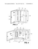
[0032]FIG. 4 shows a building entrance terminal box 100 having a smaller capacity with modules 150 installed and a blank filler panel 151. This figure also shows a support (unnumbered) to which the flanges are connected in this particular installation.
[0033]A modular panel 150 is shown in the connection and includes a surge protection field 152 and an output termination device 154. A surge protector module 158 is shown mounted in the surge protection field. While only one such module is shown, in fact 25 such modules could be placed within this field. The input wire termination device 156 and the output wire termination device 154 are a particular type commonly used in the industry and known as a 110C connector. The input connector may be mounted within the splice chamber and connected to the incoming wires in the standard arrangement. This connector is designed as either a male half or female half of the connector and the corresponding half, as will be later described, may be mounted thereon.
[0034]FIG. 5 shows a perspective view of the modules being installed within the box. Two modules are shown in this view each being similar to the modules shown in FIG. 4. Each module is box shaped with the surge protector field and the output termination device being mounted on a top surface. The bottom of the box is open for access to the terminals which extend through the top surface in a similar fashion to the prior art. On the right hand end of the box at a lower edge, a flange 160 extends to the right and carries two tabs 162. The right hand edge of the inside of the terminal box includes slots for receiving the tabs 162 and thus locating the position of the modules. Since the box is large enough to receive two or more modules, a series of such openings are provided. When installing the module, the tabs 162 are arranged in the openings in the wall of the box by angling the module as shown in FIG. 5. Once the tabs are in position and the right hand end is fixed, the left hand end is pushed downwardly to snap the module into position. A right angle flange is provided along the top of wall 130 so as to hold the left hand end of each module in position. Alternatively, it would also be possible to include a single screw in the module to make certain that it does not come loose. However, the preferable design is to have a snapping arrangement so that no screws are necessary. It should be noted that the two long sidewalls of each module has a notch 176 removed from the bottom edge thereof near the left hand end. This notch is to allow clearance for the ground bar 140.
[0035]As seen in FIG. 10, the ground bar 140 is L-shaped with one side 164 mounted on the raised panel located off the back surface of the box with the other side 168 extending upwardly toward the modules. The side 168 is formed in sections with openings 170 between the sections. However, the side 164 is continuous. The openings 170 are placed at the locations where the sidewalls of the module occur. This allows the section 168 to extend upwardly within the opening on the bottom of each module without contacting the sidewall of the module. The notch 176 is large enough to avoid contact with the side 164 but otherwise extends downwardly to protect the contacts on the underside of the module.
[0036]FIG. 9 shows a cross sectional view of the module 150 as it is being placed in position. A series of terminals 174 extend downwardly beneath the surge protector field. Although not shown, these terminals are used for wire wrapping wires which connect to the corresponding terminals of the output termination device. Also connected to these terminals are wires which lead to a connector 156A for mating with the input termination device 156. These wires are bundled together in a "pigtail" for each module. The connector 156A is provided at the other end of the pigtail. When installing the module, the pigtail extends to the left side of the module and slides in the slot part of the keyhole opening 132. When the module is snapped into position, the pigtail extends through the round part of the keyhole opening 132 with the connector 156A being in the splice chamber. This connector can then mate simply with connector 156.
[0037]Thus, when the modules are made in the factory wires are provided between the surge protection field and the output termination device and between the surge protection field and the connector 156A. By pre-wiring all of these connections, it is a simple matter to install the module merely by snapping it into place. The connector 156A is then simply mated with connector 156 so that the module is connected to the input connector. Thus, all of the wiring necessary to join the surge protection field with the input connector and the output connector is premade in the factory to reduce field installation time. Also, no screws, bolts or other fasteners are necessary in order to place the module in position. When the module snaps into position, it also overlies the ground bar 140 so that an easy and automatic connection can be made with the ground bar.
[0038]As seen in FIG. 9, a Y-shaped grounding connector 182 is also provided on the underside of the module. This connector extends below the level of the terminals 174 at the left end of the module over the notch 176. When the module is snapped into position, the two portions of the Y-shaped connector extend on opposite sides of section 168 of the ground bar. The two sides of the Y-shaped connector are made of bent metal and the opening between them is slightly less than the thickness of the section 168 so that good contact is made on both sides of section 168 by the two parts of connector 182. Thus, when the module is snapped into position Y-shaped connector 182 grounds the module in an automatic fashion without the necessity for screws, bolts or other connectors.
[0039]The building entrance terminal box also includes a grounding terminal 180 (FIG. 5) which may be provided at the top or bottom of the box or in other locations of either the splice or connection chamber. This terminal is not used to ground the modules, which are automatically grounded to the grounding bar 140. Instead, these are used to ground the entirety of the box to a ground leading to the input cable or other permanent grounds such as a water pipe. Further, if more than one box is installed at a given location it is possible to connect the boxes together through these terminals so that only a single outside ground is necessary with the boxes being serially connected thereto.
[0040]In the above explanation, a specific type of connector has been shown for use with the modules. However, the choice of the input and output connectors may be varied. FIGS. 6, 7 and 8 show modules with different types of output connectors. It is a simple matter to manufacture modules of the same size using different connectors so that depending on the desired connection arrangement in the box, the appropriate module may be pulled from inventory and installed in the factory. This would even allow the use of different terminals within the same box if desired. Any known connector type can be used, especially any commercially available connectors such as 110C, 3M-710, 3M-MS2, cable stub, 66 block, RJ21, RJ11, TIDC, ZIDC or other known connectors. The number of wire pairs in a module may be 25, 50, 100 or 200 or may be other numbers. Examples of combinations of input and output connectors are seen below. A large number of combinations may be formed from a relatively small number of module types.
TABLE-US-00001 Input Connector Output Connector Code Designation 110C 110C ACA* 3M-710 110C ACS* 3M-MS2 110C ACM* Cable Stub 110C ACC* 66 Block 66 Block BCB* 3M-710 66 Block BCS* 3M-MS2 66 Block BCM* Cable Stub 66 Block BCC* 3M-710 66 Block & RJ21 DCS* 3M-MS2 66 Block & RJ21 DCM* Cable Stub 66 Block & RJ21 DCC* 3M-710 T-IDC & RJ11 FCS* 3M-MS2 T-IDC & RJ11 FCM* Cable Stub T-IDC & RJ11 FCC* 3M-710 T-IDC Block LCS* 3M-MS2 T-IDC Block LCM* Cable Stub T-IDC Block LCC* 3M-710 RJ21 RCS* 3M-MS2 RJ21 RCM* Cable Stub RJ21 RCC* 3M-710 Z-IDC Conn ZCS* 3M-MS2 Z-IDC Conn ZCM* Cable Stub Z-IDC Conn ZCC*
[0041]The boxes may be provided with differing numbers of positions for modules. Thus, it is possible to install a box with a smaller number of modules than positions so that additional modules may be added at a later time. Empty positions can be filled with a blank panel to isolate the splice chamber from the connection chamber. This reduces the expense to the customer and simplifies installation.
[0042]Numerous additional modifications and variations of the present invention are possible in light of the above teachings. It is therefore to be understood that within the scope of the appended claims, the invention may be practice otherwise than is specifically described herein.
Claims:
1. A building entrance terminal box comprising:a splice chamber;a
connection chamber;a wall separating the splice chamber from the
connection chamber;an input wire termination device in the splice
chamber; andat least one module mounted in said connection chamber, said
module having a surge protection field and an output wire termination
device which are prewired on the module, said module also including a
connector prewired to said surge protection field for mating with said
input wire termination device.
2. The building entrance terminal box of claim 1, further comprising a ground bar in said connection chamber which connects to a ground connector associated with each module so that said ground connector snaps onto said ground bar when said module is installed.
3. The building entrance terminal box of claim 2, wherein said ground connector is Y-shaped.
4. The building entrance terminal box of claim 2, wherein said ground connector is mounted on a bottom of said module.
5. The building entrance terminal box of claim 2, wherein the ground bar is L-shaped in cross section with a first section being continuous and mounted on a back surface of said box and a second section being segmented and extending away from the back surface of the box for connection with the modules.
6. The building entrance terminal box of claim 5, wherein sidewalls of the modules extend into openings between segments of the second section of the ground bar.
7. The building entrance terminal box of claim 1, wherein each module has a tab arrangement along one bottom edge for being received in openings in said connection chamber in order to locate each module.
8. The building entrance terminal box of claim 1, wherein said wall includes at least one slot for receiving wires connecting said connector to said surge protection field so that said connector is received in the splice chamber while the module is placed in the connection chamber.
9. A module for use in a building entrance terminal box, said module comprising:a top surface and sidewalls depending therefrom;a surge protection field mounted on said top surface;an output termination device mounted on said top surface;said surge protection field and said output termination device being prewired along a bottom of said top surface; andan input connector prewired to said surge protection field;whereby said module may be mounted in a building entrance terminal box with the input connector mounted to an input termination device.
10. The module according to claim 9, further comprising a Y-shaped ground connector mounted on the bottom of said top surface for interconnection with a ground bar in said building entrance terminal box.
11. The module according to claim 9, wherein said surge protection field receives a plurality of surge protection modules
12. The module according to claim 9, further comprising a flange and tab arrangement along a bottom edge of one sidewall for mating with openings in said building entrance terminal box for holding the module in position within the box.
13. A building entrance terminal box, comprising:a splice chamber;a connection chamber;a wall separating the splice chamber from the connection chamber;a plurality of modules mounted in said connection chamber, each of said modules having a surge protection field and an output wire termination device prewired on the module;each module having a tab arrangement along an edge for connecting said module to said connection chamber;said connection chamber including a plurality of slot arrangements, with each slot arrangement receiving a tab arrangement of one module so as to locate the corresponding module in the connection chamber.
14. The building entrance terminal box of claim 13, wherein said module snaps into position when said tab arrangement is placed in said slot arrangement.
15. The building entrance terminal box of claim 14, further comprising a ground bar in said connection chamber.
16. The building entrance terminal box of claim 15, wherein each module includes a ground connection mounted on a bottom of said module.
17. The building entrance terminal box of claim 16, wherein the ground connector is Y-shaped and snaps onto said ground bar when said module is installed in said connection chamber.
18. The building entrance terminal box of claim 15, wherein the ground bar is L-shaped in cross section with a first section being continuous and mounted on a back surface of said box and a second section being segmented and extending away from the back surface of the box for connection with the modules.
19. The building entrance terminal box of claim 18, wherein sidewalls of the modules extend into openings between segments of the second section of the ground bar.
20. The building entrance terminal box of claim 13, wherein each module includes a connector prewired to said surge protection field for mating with an input wire termination device located in said splice chamber.
Description:
BACKGROUND OF THE INVENTION
[0001]The present invention relates to a building entrance terminal box for telecommunication lines and more particularly a building entrance protector box where the panels are modular and may be snapped into place to achieve an automatic ground.
DESCRIPTION OF THE BACKGROUND
[0002]When telephone or other communication lines enter a building such as an office building or apartment building, it is common to use a building entrance terminal box in order to connect the incoming lines with the individual lines that are used within the building. Such a prior art box 10 is shown in FIG. 1 as having two separate chambers, a splice chamber 14 and a connection chamber 16. A wall 30 divides the two chambers. The main cable from outside 12 enters the box in the splice chamber and is wired to an input wire termination device 18. The termination device is made of an array of terminal connectors 28. The individual wires from the main cable 12 are connected to a corresponding connector 28. These connectors are then connected by a bundle of wires which extend through the wall 30 into the connection chamber. The connection chamber includes a surge protector panel 22 and an output wire termination device 24. Each of the wires from the input wire termination device 18 is connected to a corresponding surge protector port 20 in the surge protector panel 22. Each port consists of a pattern of holes for receiving conductor pins of a surge protector module 25. Typically, the surge protector module is a box shaped device having a pattern of five pins which mate with the holes of the individual ports 20. These modules are designed to protect the lines from surges in the incoming telephone lines. Each protector port is then connected to one of the connectors of the output wire termination device 24. From this termination device, individual lines exit the box and are directed to various parts of the building.
[0003]FIG. 2 shows a cross-sectional view of this same device. As seen in this view, the terminal connectors 28 receive input wires 12 on a top surface and wires are wire wrapped to terminal leads 26 on a bottom surface of the connector. The wires are lead through a hole 32 in wall 30 and are wire wrapped to terminals 34 on the bottom surface of the surge protector panel 22. Outgoing wires are also wire wrapped to other terminals of the panel 22 and extend to terminals of the output termination device 24. As is also seen, the output termination device 24 and surge protector panel 22 are mounted on a panel 23 so as to divide the chamber 16 into an outer part and an inner part, with the inner part receiving the various wires. By utilizing an arrangement such as this, the splice chamber 14 is separated from the connection chamber 16. This prevents the incoming wires from possibly being short circuited to the output wires. It also allows the splice chamber to be enclosed for fire protection in the case of sparks resulting from a surge.
[0004]U.S. Pat. Nos. 6,191,357 and 5,942,725 show building entrance protector boxes having modular protector panels which are self grounding. While various modules are used in this arrangement, these are only modules for the surge protector panel and not modules for the entire connection chamber.
[0005]While the prior art devices shown in FIGS. 1 and 2 are workable, the building entrance terminal box is wired as a discrete unit that is costly and difficult to reconfigure. Thus, it does not lend itself to being used in boxes of other configurations. It does not allow a modular approach so that a series of splice chambers and ground systems of a few sizes can be kept in inventory and assembled together in a number of different configurations. When an order for a particular box is received, it is desirable that pre-wired modules may be snapped together in an enclosure of a desired size. Further, the factory or customer may remove a module and replace it at any time with little effort to form a different configuration.
SUMMARY OF THE INVENTION
[0006]The present invention is a building entrance terminal box which utilizes modular panels to simplify construction of the box in the factory and the field installation of the box. The individual panels within the connection chamber include both protector panel sections and output termination devices which are prewired. The input connector is also pre-wired to the modular panel. The modules merely snap in place and are designed to make an easy connection with the input termination device. As a result, installation time is reduced and simplified with fewer mistakes. The individual modules are also automatically grounded upon their snapping into position.
[0007]Accordingly, the present invention provides a building entrance terminal box with modular panels.
[0008]The present invention further provides a building entrance terminal box which is simple to install by using modular devices.
[0009]The present invention also provides a building entrance terminal box with an automatic grounding for modules.
[0010]The present invention still further provides a building entrance terminal box with modules that easily snap into place for fast installation.
[0011]The present invention further provides a building entrance terminal box which is simple in design and inexpensive to make and install, and to expand or retrofit by the customer in the field.
BRIEF DESCRIPTION OF THE DRAWINGS
[0012]A more complete appreciation of the invention and many of the attendant advantages will be readily appreciated as the same becomes better understood by reference to the following detailed description when considered in connection with the accompanying drawings, wherein:
[0013]FIG. 1 is a front view of a prior art device;
[0014]FIG. 2 is a cross sectional view of the prior art device of FIG. 1;
[0015]FIG. 3 is a perspective view of one example of a building entrance terminal box of the present invention;
[0016]FIG. 4 is a perspective view of a building entrance terminal box of the present invention having modular panels installed;
[0017]FIG. 5 is a cutaway view of the present invention showing the installation of modules;
[0018]FIG. 6 is a perspective view of a modular panel of a second type used in the present invention;
[0019]FIG. 7 is a perspective view of a modular panel of a third type used in the present invention;
[0020]FIG. 8 is a perspective view of a modular panel of a fourth type used in the present invention;
[0021]FIG. 9 is a cross sectional view of a module of the present invention being installed; and
[0022]FIG. 10 is a perspective view of the grounding bar used in the present invention;
DESCRIPTION OF THE PREFERRED EMBODIMENTS
[0023]The present invention now is described more fully hereinafter with reference to the accompanying drawings, in which embodiments of the invention are shown. This invention may, however, be embodied in many different forms and should not be construed as limited to the embodiments set forth herein; rather, these embodiments are provided so that this disclosure will be thorough and complete, and will fully convey the scope of the invention to those skilled in the art.
[0024]Like numbers refer to like elements throughout. In the figures, the thickness of certain lines, layers, components, elements or features may be exaggerated for clarity. Broken lines illustrate optional features or operations unless specified otherwise.
[0025]The terminology used herein is for the purpose of describing particular embodiments only and is not intended to be limiting of the invention. Unless otherwise defined, all terms (including technical and scientific terms) used herein have the same meaning as commonly understood by one of ordinary skill in the art to which this invention belongs. It will be further understood that terms, such as those defined in commonly used dictionaries, should be interpreted as having a meaning that is consistent with their meaning in the context of the specification and relevant art and should not be interpreted in an idealized or overly formal sense unless expressly so defined herein. Well-known functions or constructions may not be described in detail for brevity and/or clarity.
[0026]As used herein, the singular forms "a", "an" and "the" are intended to include the plural forms as well, unless the context clearly indicates otherwise. It will be further understood that the terms "comprises" and/or "comprising," when used in this specification, specify the presence of stated features, integers, steps, operations, elements, and/or components, but do not preclude the presence or addition of one or more other features, integers, steps, operations, elements, components, and/or groups thereof. As used herein, the term "and/or" includes any and all combinations of one or more of the associated listed items. As used herein, phrases such as "between X and Y" and "between about X and Y" should be interpreted to include X and Y. As used herein, phrases such as "between about X and Y" mean "between about X and about Y." As used herein, phrases such as "from about X to Y" mean "from about X to about Y."
[0027]It will be understood that when an element is referred to as being "on", "attached" to, "connected" to, "coupled" with, "contacting", etc., another element, it can be directly on, attached to, connected to, coupled with or contacting the other element or intervening elements may also be present. In contrast, when an element is referred to as being, for example, "directly on", "directly attached" to, "directly connected" to, "directly coupled" with or "directly contacting" another element, there are no intervening elements present. It will also be appreciated by those of skill in the art that references to a structure or feature that is disposed "adjacent" another feature may have portions that overlap or underlie the adjacent feature.
[0028]Spatially relative terms, such as "under", "below", "lower", "over", "upper", "lateral", "left", "right" and the like, may be used herein for ease of description to describe one element or feature's relationship to another element(s) or feature(s) as illustrated in the figures. It will be understood that the spatially relative terms are intended to encompass different orientations of the device in use or operation in addition to the orientation depicted in the figures. For example, if the device in the figures is inverted, elements described as "under" or "beneath" other elements or features would then be oriented "over" the other elements or features. The device may be otherwise oriented (rotated 90 degrees or at other orientations) and the descriptors of relative spatial relationships used herein interpreted accordingly.
[0029]The entrance terminal box of the present invention is shown as 100 in FIG. 3. The box includes a splice chamber 114 and connection chamber 116, in a similar fashion to the prior art. A wall 130 divides the two chambers. However, keyholes 132 are provided for receiving wire connections between the input termination device and the modular panels. An outer door 142 is provided to enclose the box for security and safety purposes. A latching arrangement 144, which may include a lock is provided on the door and the frame in order to hold the door securely. An inner door 146 is also provided to completely enclose the splice chamber. It also extends into the connection chamber to cover the surge protector panel. This is designed to prevent the wires from the splice chamber from coming into contact with the wires in the connection chamber and also provides a fire resistant chamber. A ground bar 140 is mounted in the connection chamber near the wall 130. This grounding bar is in the shape of an L in cross section with one surface being mounted on a raised panel on the back of the enclosure and the other surface extending outwardly from the back.
[0030]A flange 148 for mounting the box is provided on opposite sides. Mounting devices such as slots are also provided to fit a standard 23 inch network bay frame with WECO spacing as well as a network bay frame with ETSI spacing without the need for an adaptor kit.
[0031]The device shown in FIG. 3 is designed to receive several modules. It may also be arranged in a shorter version to receive a smaller number of modules, depending on the needs of the installation. Each module is designed for a certain number of connections. Thus, a larger box may be provided than is initially necessary and modules may be installed as needed to increase the capacity of the system. This provides additional benefits to the user in terms of a lower initial cost and the capability of expanding the system easily.
[0032]FIG. 4 shows a building entrance terminal box 100 having a smaller capacity with modules 150 installed and a blank filler panel 151. This figure also shows a support (unnumbered) to which the flanges are connected in this particular installation.
[0033]A modular panel 150 is shown in the connection and includes a surge protection field 152 and an output termination device 154. A surge protector module 158 is shown mounted in the surge protection field. While only one such module is shown, in fact 25 such modules could be placed within this field. The input wire termination device 156 and the output wire termination device 154 are a particular type commonly used in the industry and known as a 110C connector. The input connector may be mounted within the splice chamber and connected to the incoming wires in the standard arrangement. This connector is designed as either a male half or female half of the connector and the corresponding half, as will be later described, may be mounted thereon.
[0034]FIG. 5 shows a perspective view of the modules being installed within the box. Two modules are shown in this view each being similar to the modules shown in FIG. 4. Each module is box shaped with the surge protector field and the output termination device being mounted on a top surface. The bottom of the box is open for access to the terminals which extend through the top surface in a similar fashion to the prior art. On the right hand end of the box at a lower edge, a flange 160 extends to the right and carries two tabs 162. The right hand edge of the inside of the terminal box includes slots for receiving the tabs 162 and thus locating the position of the modules. Since the box is large enough to receive two or more modules, a series of such openings are provided. When installing the module, the tabs 162 are arranged in the openings in the wall of the box by angling the module as shown in FIG. 5. Once the tabs are in position and the right hand end is fixed, the left hand end is pushed downwardly to snap the module into position. A right angle flange is provided along the top of wall 130 so as to hold the left hand end of each module in position. Alternatively, it would also be possible to include a single screw in the module to make certain that it does not come loose. However, the preferable design is to have a snapping arrangement so that no screws are necessary. It should be noted that the two long sidewalls of each module has a notch 176 removed from the bottom edge thereof near the left hand end. This notch is to allow clearance for the ground bar 140.
[0035]As seen in FIG. 10, the ground bar 140 is L-shaped with one side 164 mounted on the raised panel located off the back surface of the box with the other side 168 extending upwardly toward the modules. The side 168 is formed in sections with openings 170 between the sections. However, the side 164 is continuous. The openings 170 are placed at the locations where the sidewalls of the module occur. This allows the section 168 to extend upwardly within the opening on the bottom of each module without contacting the sidewall of the module. The notch 176 is large enough to avoid contact with the side 164 but otherwise extends downwardly to protect the contacts on the underside of the module.
[0036]FIG. 9 shows a cross sectional view of the module 150 as it is being placed in position. A series of terminals 174 extend downwardly beneath the surge protector field. Although not shown, these terminals are used for wire wrapping wires which connect to the corresponding terminals of the output termination device. Also connected to these terminals are wires which lead to a connector 156A for mating with the input termination device 156. These wires are bundled together in a "pigtail" for each module. The connector 156A is provided at the other end of the pigtail. When installing the module, the pigtail extends to the left side of the module and slides in the slot part of the keyhole opening 132. When the module is snapped into position, the pigtail extends through the round part of the keyhole opening 132 with the connector 156A being in the splice chamber. This connector can then mate simply with connector 156.
[0037]Thus, when the modules are made in the factory wires are provided between the surge protection field and the output termination device and between the surge protection field and the connector 156A. By pre-wiring all of these connections, it is a simple matter to install the module merely by snapping it into place. The connector 156A is then simply mated with connector 156 so that the module is connected to the input connector. Thus, all of the wiring necessary to join the surge protection field with the input connector and the output connector is premade in the factory to reduce field installation time. Also, no screws, bolts or other fasteners are necessary in order to place the module in position. When the module snaps into position, it also overlies the ground bar 140 so that an easy and automatic connection can be made with the ground bar.
[0038]As seen in FIG. 9, a Y-shaped grounding connector 182 is also provided on the underside of the module. This connector extends below the level of the terminals 174 at the left end of the module over the notch 176. When the module is snapped into position, the two portions of the Y-shaped connector extend on opposite sides of section 168 of the ground bar. The two sides of the Y-shaped connector are made of bent metal and the opening between them is slightly less than the thickness of the section 168 so that good contact is made on both sides of section 168 by the two parts of connector 182. Thus, when the module is snapped into position Y-shaped connector 182 grounds the module in an automatic fashion without the necessity for screws, bolts or other connectors.
[0039]The building entrance terminal box also includes a grounding terminal 180 (FIG. 5) which may be provided at the top or bottom of the box or in other locations of either the splice or connection chamber. This terminal is not used to ground the modules, which are automatically grounded to the grounding bar 140. Instead, these are used to ground the entirety of the box to a ground leading to the input cable or other permanent grounds such as a water pipe. Further, if more than one box is installed at a given location it is possible to connect the boxes together through these terminals so that only a single outside ground is necessary with the boxes being serially connected thereto.
[0040]In the above explanation, a specific type of connector has been shown for use with the modules. However, the choice of the input and output connectors may be varied. FIGS. 6, 7 and 8 show modules with different types of output connectors. It is a simple matter to manufacture modules of the same size using different connectors so that depending on the desired connection arrangement in the box, the appropriate module may be pulled from inventory and installed in the factory. This would even allow the use of different terminals within the same box if desired. Any known connector type can be used, especially any commercially available connectors such as 110C, 3M-710, 3M-MS2, cable stub, 66 block, RJ21, RJ11, TIDC, ZIDC or other known connectors. The number of wire pairs in a module may be 25, 50, 100 or 200 or may be other numbers. Examples of combinations of input and output connectors are seen below. A large number of combinations may be formed from a relatively small number of module types.
TABLE-US-00001 Input Connector Output Connector Code Designation 110C 110C ACA* 3M-710 110C ACS* 3M-MS2 110C ACM* Cable Stub 110C ACC* 66 Block 66 Block BCB* 3M-710 66 Block BCS* 3M-MS2 66 Block BCM* Cable Stub 66 Block BCC* 3M-710 66 Block & RJ21 DCS* 3M-MS2 66 Block & RJ21 DCM* Cable Stub 66 Block & RJ21 DCC* 3M-710 T-IDC & RJ11 FCS* 3M-MS2 T-IDC & RJ11 FCM* Cable Stub T-IDC & RJ11 FCC* 3M-710 T-IDC Block LCS* 3M-MS2 T-IDC Block LCM* Cable Stub T-IDC Block LCC* 3M-710 RJ21 RCS* 3M-MS2 RJ21 RCM* Cable Stub RJ21 RCC* 3M-710 Z-IDC Conn ZCS* 3M-MS2 Z-IDC Conn ZCM* Cable Stub Z-IDC Conn ZCC*
[0041]The boxes may be provided with differing numbers of positions for modules. Thus, it is possible to install a box with a smaller number of modules than positions so that additional modules may be added at a later time. Empty positions can be filled with a blank panel to isolate the splice chamber from the connection chamber. This reduces the expense to the customer and simplifies installation.
[0042]Numerous additional modifications and variations of the present invention are possible in light of the above teachings. It is therefore to be understood that within the scope of the appended claims, the invention may be practice otherwise than is specifically described herein.
User Contributions:
Comment about this patent or add new information about this topic:
Images included with this patent application:
 |  |
 |  |
 |  |
 |
| New patent applications in this class: | |
| Date | Title |
|---|---|
| 2016-07-14 | Modular electrical wiring device system |
| 2016-02-18 | Movable ground ring for movable substrate support assembly of a plasma processing chamber |
| 2015-04-30 | Metallisation of a housing of an aeronautic engine made of electrically insulating material |
| 2015-04-23 | Block for electrical bonding and grounding |
| 2015-02-19 | Grounding conductor |
| Top Inventors for class "Electricity: conductors and insulators" | |
| Rank | Inventor's name |
|---|---|
| 1 | Douglas B. Gundel |
| 2 | Shou-Kuo Hsu |
| 3 | Michimasa Takahashi |
| 4 | Hideyuki Kikuchi |
| 5 | Tsung-Yuan Chen |