Patent application title: AUTOMATIC SYSTEM FOR EVAPORATION OF CONDENSATES
Inventors:
Francisco Javier Santana Leon (Santa Cruz De Tenerife, ES)
IPC8 Class: AF25D2114FI
USPC Class:
62150
Class name: Refrigeration automatic control preventing, removing or handling atmospheric condensate
Publication date: 2010-05-06
Patent application number: 20100107666
ion of a set of condensation control elements on
to the lower rear part of the external condenser units of
air-conditioning systems, permitting the elimination by evaporation of
the liquid formed in the air-conditioning process.
The system is made up of an electric liquid level sensor, which is
connected to the liquid collection container on the bottom of the
external condenser unit, and which, depending on the level of liquid in
the container, activates the pump, which pumps the water through pipes
connected to the rear ventilation grille and releases it on to the
condenser through atomizers at the end of the pipes, causing the liquid
to evaporate, thereby making it unnecessary to install condensed liquid
drainage pipes and improving heat efficiency by cooling the ventilation
grille of the condenser unit.Claims:
1. Automatic condensed liquid evaporation system comprising a combination
of elements consisting of a liquid pump, a liquid level sensor and a set
of pipes with atomizers on the end, which are placed on the external
condenser units of air-conditioning systems in such a way as to collect
the condensed liquid which accumulates in the lower tray of the condenser
and release it in the form of a fine spray over the top of the
ventilation grille of the external condenser unit.
2. Automatic condensed liquid evaporation system as claimed in claim 1, comprising an electric liquid level sensor which activates the pump-also electric-only when it detects the presence of a high enough level of liquid in the tray for the collection of water from the drainage pipes of the evaporating and condensing units of the air-conditioning system.Description:
PURPOSE OF THE INVENTION
[0001]The Invention Patent to which this Report refers is intended to guarantee the exclusive use and ownership, throughout the country, of an automatic system of evaporation of the condensed liquid from air-conditioning and cooling units.
SCOPE OF THE INVENTION
[0002]The application of this invention is in the temperature and moisture exchange requirements, especially the evaporation of the liquid condensed during the air-conditioning process (F25), which arise in evaporators due to condensation.
[0003]This invention has two important purposes: firstly, it solves one of the most serious problems of domestic air-conditioning units, namely, the present need for complicated systems for the drainage of condensed liquids and, secondly, it significantly increases the heat efficiency of the unit and reduces power consumption.
BACKGROUND OF THE INVENTION
[0004]Nowadays, air-conditioning is the most complete process of ambient air treatment, involving the regulation of conditions in terms of temperature (heating or cooling), moisture and quality (renewal, filtering).
[0005]Over the last few years, the installation of air-conditioning units has become an essential requirement to achieve people's wellbeing in domestic, work and leisure environments.
[0006]The technique has advanced to such an extent that, nowadays, there are many low-price, high-performance, easily installed, noise-free air-conditioning systems on the market, but they all lack optimum systems for the elimination of the condensed liquids produced by the various units of which they are composed.
DESCRIPTION OF THE INVENTION
[0007]The invention consists of an adaptation to the external condenser unit, such that by installing the device for collecting the water condensed in the air-conditioning process, in which a simple electric pump for condensed liquids, a liquid level sensor and a set of small vertical pipes with atomizers at the end are installed, the condensed water is pumped over the external unit condenser and, thanks to the high temperature of the latter and the action of the equipment's fan, along with moisture exchange, the condensed liquid evaporates into the outside air, eliminating the need to include drainage pipes and/or containers for the collection of condensed liquids.
DESCRIPTION OF THE DIAGRAMS
[0008]To better understand the scope of this invention, we are going to describe it using the attached diagrams, which show a preferred design of the same, given as an example but not being the only possibility.
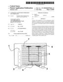
[0009]FIG. 1 shows a rear view of an external condenser unit with the invention installed and
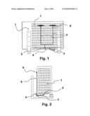
[0010]FIG. 2 shows a side view of the same.
[0011]We can see that, in the diagrams, (1) represents the external condenser unit of an air-conditioning system, (2) the container for condensed liquids, (3) the liquid level sensor, (4) the pump, (5) the vertical pipes, (6) the atomizers and (7) the ventilation grille.
PREFERENTIAL FORMAT OF THE INVENTION
[0012]As you can see in the diagrams, the invention is located on the condenser unit of an air-conditioning system (1) and consists of a liquid level sensor (3), which detects the presence and level of liquid accumulated in the condensed liquid collection container (2) and, when the liquid in the container reaches a high enough level, activates the electric pump (4). The latter pumps the condensed liquid through the rear vertical pipes (5), attached to the external condenser unit ventilation grille, from which it is released through the atomizers (6) in the form of a fine spray.
[0013]The water released through the atomizers (6) falls directly on to the rear ventilation grille (7) of the condenser unit (1), where it quickly evaporates due both to the temperature of the condenser and the effect of the internal fan of the condenser, as well as the moisture of the outside air.
[0014]When the level of liquid in the condensed liquid collection container (2) drops, this is detected by the sensor, which turns off the pump and therefore the atomizers.
[0015]As you can see, the invention is as effective as it is simple and original. This set of elements: the sensor, the pump, the pipes and the atomizers are easy to handle and install and inexpensive.
[0016]With the invention, installation costs are also significantly reduced, since, as already mentioned, it makes it unnecessary to install drainage pipes, which often disfigure the facades of buildings. Energy costs are also reduced, since the water released on to the ventilation grille by the atomizers aids in the elimination of heat and improves the heat efficiency of the installation, as shown in the attached diagrams.
[0017]Apart from the basic invention, the patent also includes variations in detail, such that there may be variations in the type of level sensor and pump, the characteristics and quantity of pipes and atomizers, the size of the different parts of the system and, naturally, the material used.
Claims:
1. Automatic condensed liquid evaporation system comprising a combination
of elements consisting of a liquid pump, a liquid level sensor and a set
of pipes with atomizers on the end, which are placed on the external
condenser units of air-conditioning systems in such a way as to collect
the condensed liquid which accumulates in the lower tray of the condenser
and release it in the form of a fine spray over the top of the
ventilation grille of the external condenser unit.
2. Automatic condensed liquid evaporation system as claimed in claim 1, comprising an electric liquid level sensor which activates the pump-also electric-only when it detects the presence of a high enough level of liquid in the tray for the collection of water from the drainage pipes of the evaporating and condensing units of the air-conditioning system.
Description:
PURPOSE OF THE INVENTION
[0001]The Invention Patent to which this Report refers is intended to guarantee the exclusive use and ownership, throughout the country, of an automatic system of evaporation of the condensed liquid from air-conditioning and cooling units.
SCOPE OF THE INVENTION
[0002]The application of this invention is in the temperature and moisture exchange requirements, especially the evaporation of the liquid condensed during the air-conditioning process (F25), which arise in evaporators due to condensation.
[0003]This invention has two important purposes: firstly, it solves one of the most serious problems of domestic air-conditioning units, namely, the present need for complicated systems for the drainage of condensed liquids and, secondly, it significantly increases the heat efficiency of the unit and reduces power consumption.
BACKGROUND OF THE INVENTION
[0004]Nowadays, air-conditioning is the most complete process of ambient air treatment, involving the regulation of conditions in terms of temperature (heating or cooling), moisture and quality (renewal, filtering).
[0005]Over the last few years, the installation of air-conditioning units has become an essential requirement to achieve people's wellbeing in domestic, work and leisure environments.
[0006]The technique has advanced to such an extent that, nowadays, there are many low-price, high-performance, easily installed, noise-free air-conditioning systems on the market, but they all lack optimum systems for the elimination of the condensed liquids produced by the various units of which they are composed.
DESCRIPTION OF THE INVENTION
[0007]The invention consists of an adaptation to the external condenser unit, such that by installing the device for collecting the water condensed in the air-conditioning process, in which a simple electric pump for condensed liquids, a liquid level sensor and a set of small vertical pipes with atomizers at the end are installed, the condensed water is pumped over the external unit condenser and, thanks to the high temperature of the latter and the action of the equipment's fan, along with moisture exchange, the condensed liquid evaporates into the outside air, eliminating the need to include drainage pipes and/or containers for the collection of condensed liquids.
DESCRIPTION OF THE DIAGRAMS
[0008]To better understand the scope of this invention, we are going to describe it using the attached diagrams, which show a preferred design of the same, given as an example but not being the only possibility.
[0009]FIG. 1 shows a rear view of an external condenser unit with the invention installed and
[0010]FIG. 2 shows a side view of the same.
[0011]We can see that, in the diagrams, (1) represents the external condenser unit of an air-conditioning system, (2) the container for condensed liquids, (3) the liquid level sensor, (4) the pump, (5) the vertical pipes, (6) the atomizers and (7) the ventilation grille.
PREFERENTIAL FORMAT OF THE INVENTION
[0012]As you can see in the diagrams, the invention is located on the condenser unit of an air-conditioning system (1) and consists of a liquid level sensor (3), which detects the presence and level of liquid accumulated in the condensed liquid collection container (2) and, when the liquid in the container reaches a high enough level, activates the electric pump (4). The latter pumps the condensed liquid through the rear vertical pipes (5), attached to the external condenser unit ventilation grille, from which it is released through the atomizers (6) in the form of a fine spray.
[0013]The water released through the atomizers (6) falls directly on to the rear ventilation grille (7) of the condenser unit (1), where it quickly evaporates due both to the temperature of the condenser and the effect of the internal fan of the condenser, as well as the moisture of the outside air.
[0014]When the level of liquid in the condensed liquid collection container (2) drops, this is detected by the sensor, which turns off the pump and therefore the atomizers.
[0015]As you can see, the invention is as effective as it is simple and original. This set of elements: the sensor, the pump, the pipes and the atomizers are easy to handle and install and inexpensive.
[0016]With the invention, installation costs are also significantly reduced, since, as already mentioned, it makes it unnecessary to install drainage pipes, which often disfigure the facades of buildings. Energy costs are also reduced, since the water released on to the ventilation grille by the atomizers aids in the elimination of heat and improves the heat efficiency of the installation, as shown in the attached diagrams.
[0017]Apart from the basic invention, the patent also includes variations in detail, such that there may be variations in the type of level sensor and pump, the characteristics and quantity of pipes and atomizers, the size of the different parts of the system and, naturally, the material used.
User Contributions:
Comment about this patent or add new information about this topic:
Images included with this patent application:
 |  |
| Similar patent applications: | |
| Date | Title |
|---|---|
| 2011-10-20 | Air flow system for appliances |
| 2012-09-06 | Heat cycle system for mobile object |
| 2012-10-18 | Method for the fast formation of a gas hydrate |
| 2013-09-12 | Wetting of evaporative cooler pads |
| New patent applications in this class: | |
| Date | Title |
|---|---|
| 2022-05-05 | Heat exchanger and vehicle air conditioning system |
| 2016-05-19 | Cooling system for high density heat load |
| 2015-11-12 | Overflow safety switch mounting device |
| 2014-10-09 | Vehicle air-conditioning apparatus |
| 2014-05-15 | In-vehicle absorption heat pump device |
| Top Inventors for class "Refrigeration" | |
| Rank | Inventor's name |
|---|---|
| 1 | Michael F. Taras |
| 2 | Alexander Lifson |
| 3 | Koji Yamashita |
| 4 | Hiroyuki Morimoto |
| 5 | Patrick J. Boarman |